Servicing consumer electronic products can be a lot of fun, if you let it be. Just like solving a great murder mystery, the smart detective must have the skill, desire, and ability to find the culprit. The electronics technician must take the symptom and ate, locate, remove, and replace the defective part.
The anticipation of locating a dead, open, or leaky component is like finding a needle in a haystack ( FIG. 1). Your heart beats a little faster as you zoom in on the suspected part. Then great disappointment sets in when the suspected component is not the guilty party. So you try once again.
Troubleshooting the TV chassis, VCR, CD player, and cassette player presents many rewards. Solving the intermittent or tough-dog problem is a moment of triumph. However, if you can repair and service the electronic chassis without a schematic, you receive the highest honors of all. So let’s begin.
Take a good look
Take a good look at the defective chassis. Visual inspection has repaired thou sands of electronic chassis. Watch out for visual scars, like a burned resistor, worn connections, arc-over parts, cracked boards, overheated components, and wear and tear.
For example, firing or arcing inside the picture tube can indicate a cracked CRT gun assembly. Arcing between parts on PC boards results from liquid spilled inside the chassis. Smoke curling up from overheated components signals trouble ahead. When sweat forms on a carbon resistor, an overheated circuit is nearby.
Cracked or blown resistors or capacitors show signs of higher voltage or defective parts. Arcing inside the flyback transformer indicates leaky high-voltage diodes. Overheated white and dark marks on the IC body might point out a leaky part. Cracks found in ceramic capacitors and resistors indicate overheated components.

FIG. 1 Locate the defective component with critical volt resistance, and
diode tests with the DMM.

FIG. 2 Look for large 5- and 10-W resistors with cracked areas, burned
parts, and hot components upon the chassis.
The damaged or frozen voice coil of a PM speaker won’t move with audio. Too-hot- to-touch transistors or ICs might be leaky or shorted.
Several burned resistors might point to a leaky transistor or IC. Taking a close up peek through a magnifying glass might solve the intermittent problem. Dark- brown areas around the component terminal leads on PC boards can indicate a poor connection or overheated part. Just spend a little time before jumping to conclusions. Look before isolation, then take another peek at the collected symptoms.
Listen, listen
You should be able to hear the TV chassis with high voltage by listening with your ear close to the deflection yoke. Listen for arcing in the flyback or a tic-tic noise indicating horizontal problems. Intermittent arcing noise within a defective capacitor can indicate an internal break or loose terminal wire.
Check the main filter capacitors when an extreme hum is heard in the speaker. A low hum noise can be caused by dried-up decoupling capacitors. Pickup hum might point toward a poor ground or an open base circuit. Hum with distorted audio might originate in the output transistors or IC components in stereo circuits. A mushy speaker sound might be caused by a dropped or frozen voice coil.
Some women can hear the frequency of horizontal circuits, while most people cannot hear over 10 kilocycles. The singing flyback might be caused by loose particles or loose mounting. Don’t overlook a vibrating ferrite bead that might dislodge or come loose.
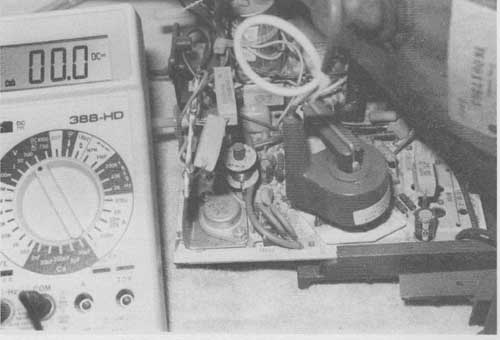
FIG. 3 A tic-tic noise heard from the flyback transformer can indicate
problems within the horizontal output circuits.
Low frying noises in large power amps might be caused by defective transistors or IC components. Especially check ceramic capacitors, transistors, and IC parts in the front end of stereo or cassette tape amplifiers. Loose grounds or soldered joints might cause microphonic noises in the input and output stages of the amplifier.
Hands have it
You can tell if the soldering iron is warm, cold, on the blink, or shut off by holding it near your arm. Don’t touch it. Locate the shorted yoke by removing it and feeling the inside area. Replace the yoke assembly if hot spots are found ( FIG. 4). Feel the outside winding of a power transformer or flyback, with the power off; heat might indicate shorted windings or overloading.

FIG. 4 Leakage between the horizontal and vertical windings and hot spots
in the yoke can indicate a defective yoke.
The overloaded transistor or IC component can be located by touch. The same applies to resistors, choke coils, and pincushion parts. Touch the neck of the picture tube for warmth when you cannot see any filament or heater light up. Feel large high-voltage resistors for overheating and overloading.
Feel the speaker cone, by pushing it in and out, to determine if the voice coil is dragging. Loud speaker vibration can be felt with fingers on the speaker cone area. Intermittent voice coil connection can be felt with the volume turned up and fingers pressed against the speaker cone. Vibrating components on the chassis can be indicated by exerting pressure on the suspected area. Touch can locate a lot of different problems in the electronic chassis.
Bright lights and Broadway
The excessively bright raster symptom without any control might result from a defective picture tube or CRT circuits, or a change in boost voltage. Usually B+ boost voltage is developed in the derived secondary circuits of the horizontal transformer. An open or burned isolation resistor or silicon diode or a dried-up filter capacitor can cause improper boost voltage. The excessive bright raster, followed by shutdown, might be caused by a defective picture tube.
High-voltage arc-over can be seen at the anode connection on the picture tube. If liquid is spilled on the CRT, arc-over between the anode and the aqueduct coating or ground spring can occur. Rubber damage on the anode button or socket can result in bright high-voltage arc-over. A pinched or cracked high-voltage anode cable results in bright arcing to parts or chassis.
Often when high voltage arcs over at the CRT anode socket, excessive high voltage is caused by a defective flyback or safety capacitor. This capacitor, located across the damper diode or attached to the collector terminal, might open up, letting the horizontal output increase and resulting in uncontrollable high-voltage arc-over.
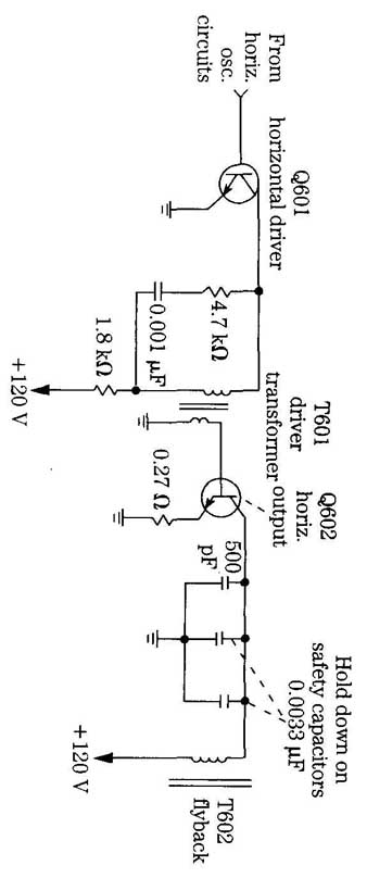
FIG. 5 Open safety or hold down capacitors in the collector circuit of
the horizontal output transistor can cause HV arcs and cracking noises.
Bright arcing with popping noises, between the tripler unit and metal chassis, may be found in the early TV chassis. The high voltage increases with a breakdown of HV diodes and capacitors within the tripler unit. Always replace the tripler unit, then try to repair it.
Sometimes arcing within the picture tube can be caused by a cracked glass or open filament. Thin bright arcing lines found in the raster might be caused by a defective focus control. White-blue arcing lines within the spark gap, found on the CRT terminals, might result from internal element leakage, excessive high voltage, or a dirty or clogged spark gap assembly. Shut down the chassis at once to prevent further damage.
Snap, crackle, and stop
Cracking or popping sounds in the speaker might be caused by a defective audio output transistor or IC. Isolate the output stage. Component replacement is the only answer. Low popping noises can be caused by defective ICs or transistors. Spray the component with coolant, and if the noise stops, replace the suspected component. Low frying or firing noises can be caused by a defective input transistor or IC.
When switched, a dirty function switch might produce scratching or cracking noises in the speaker ( FIG. 6). You might find one or two dead circuits with dirty switch contacts. Spray cleaning fluid inside the switch area, arid work the switch control on and off to help clean the contacts. Replace the switch if it cannot be cleaned or has worn contacts.
High-voltage arc-over and popping noises are caused by excessive high voltage. When the TV chassis starts up or shuts down, a cracking noise can be heard. Of course, no problem exists with the yoke assembly expanding and collapsing with signal applied and turned off. This is a good cracking sound.
Smoke gets in your eyes
Where there is smoke, there is fire, so the saying goes. This also applies to troubles that occur in the electronic chassis. Suspect a shorted power transformer with smoke and odors rising from the low-voltage circuits. Often, small power transformers with leaky silicon diodes or leaky filter capacitors might open the primary winding. In large power transformers, found in high-voltage stereo amplifiers, the shorted transformer might burn or smoke.
Dirty switch contacts

FIG. 6 Dirty switches within the AM-FM-MPX receiver amp causes cracking
and firing noises in the speaker.
Remove all secondary leads from the power transformer to the power circuits and let the transformer cool down. Again turn the chassis on. If the transformer be gins to smoke and run excessively warm, replace it. Remember, power transformers are rather expensive and sometimes difficult to obtain.
When liquid is spilled in an area where higher-than-normal voltage is found, firing on the PC board results. Smoke will curl upwards and holes will be burned in the board if the unit is left on. Firing and arcing between components and wiring might melt down and destroy a few parts before the chassis is shut off. Arc-over between horizontal and vertical windings in the yoke assembly might be caused by liquid spilled into the yoke or breakdown within yoke assembly.
Separate PC board replacement is costly, and many times they are difficult to obtain. Repair the board if possible. Make a rough drawing or sketch of the replacement parts, PC wiring, and terminal connections. Remove defective parts. Install new parts on a terminal strip or small PC board.
Small burned spots on a board can be repaired by replacing burned or charred components. Spray on a cleaner/degreaser to wash away dirt from the parts and circuit. Scrape off burned areas with a pocket knife or flat tool. Replace burned components with new parts. Recheck for overheating, arcing, and smoke after repairs. Spray on a light coat of premium preservative fluid and let dry.

FIG. 7 Pepsi, Coke, or liquid spilled down into the yoke assembly can
cause arcs and smoke curl upwards.
Often the horizontal-output transformer must be replaced when heavy arcing is found within the high-voltage windings or diodes. Replace the flyback with the original part number. A sweet smell of germanium, which might not include smoke, is caused by a leaky high-voltage diode in the black-and-white TV chassis.
Hit between the eyes
Most symptoms are found by sight, sound, or touch. Of course, test equipment is needed to check voltage, resistance, current, waveforms, and continuity on the various components. Isolating and pinpointing the defective part is the most difficult job in troubleshooting. It only takes a few minutes to replace a defective part after locating it.
Sometimes we try too hard to locate a problem, when the defective part is staring up at us, right under our eyes ( FIG. 8). It’s best to get away from the chassis when a defective part cannot be found in one hour. The longer you stay with it, the more dark and clouded the scene becomes.
A little common sense, electronics knowledge, the correct test equipment, and experience can help you locate the tough dog. When the mind is free and clear, early in the morning, tackle that tough repair problem.

FIG. 8 Check the chassis over carefully, as the defective component is
looking you right in the face.
Nose to the grindstone
After working on a chassis for several hours, you might want to give up. Why not try a different approach or method of troubleshooting? Each electronics technician has his or her own method of troubleshooting an electronic product and does not want to change. Have you tried asking fellow technicians if they have had the same problem? Help can be obtained from electronics distributors and service departments. Why not ask the manufacturer for help? Help is out there; just ask for it. Some manufacturers have service centers around the country where their electronic products can be serviced.
Don’t give up the ship. Keep your nose to the grindstone. Sometimes you wonder if this job is all worth it. You bet it is. There is no greater satisfaction than licking that tough-dog problem.
Different model, same chassis
The electronics manufacturers use several chassis that are the same, year in and year out. The cabinet and outside dressing are changed, but the insides are essentially the same. In fact, the same chassis might be found in other brands of TVs.
Let’s take the RCA XL100 chassis, which can be found in many different TVs. The CTC87, CTC97, CTC1O7, CTC1O8, and CTC1O9 have practically the same circuits. Although you might find some modifications, they have the same basic circuits. If you have a schematic for an RCA CTC1O7 chassis, why not use it for the other chassis when the correct schematic is not handy?

FIG. 9 The RCA CTC 107 has the same circuits as the CTC87, CTC97, CTC
108, and CTC 109.
Often the horizontal and vertical circuits are the same. A different tuner might be used, but the IF sections are identical. The same color IC might be used in several dozen TV chassis. So why not try to use a schematic that is similar to the chassis found on your service bench, instead of waiting for months for the exact diagram?
Same track record
Remember, the circuits found on the schematic of a manufacturer might be used in many different chassis. Some firms have their own pet circuits that are used in many different chassis, including other brands. In fact, several overseas companies make electronic units for other brands. These units may not look the same, but in side they are the same circuits.
When a breakdown occurs in one chassis, look for the same part to break down in other chassis. Sometimes the same component fails in many different chassis. You can make money on these types of repairs because they occur over and over. however, it’s difficult to remember what parts break down in several hundred different chassis each year. Write it down.
Keep the service data in a notebook, in card file, or on a computer. The best place is to write it down on the service schematic. Circle the defective component, draw a line out to the side, and write down the symptom. Circle the voltages that are measured when the part is defective, with proper waveforms ( FIG. 10).

FIG. 10 Write the various symptoms, defective components, and voltages
down on the margin of the schematic diagram.
Making a written record of your repair procedures and problems might help you and your fellow technicians troubleshoot that same symptom when it happens again. Take good clean service notes and precious service time can be saved. Besides, it’s easy money the next time around.
Service notes and troubleshooting tips by the manufacturer or service center can be added to the same chassis. If you are a warranty station for several brands of electronic products, the firm passes on troubleshooting guidelines that can help in servicing the tough-dog chassis. Of course, manufacturers’ service meetings and seminars are worth their weight in gold. Take a few hours away from the bench to gain valuable knowledge.
Just take a few minutes to write down the defective component on the schematic. Compare another schematic to the chassis when the exact diagram is not handy. Remember, the same part might break down in another chassis.
Highway lines
Two yellow lines down the middle of the highway divide the corning and going traffic in half, while white lines along the outside edge of the asphalt show the edge of the pavement. Unwanted lines in the TV picture must be erased for a good viewing picture. Sharp, jagged, or dotted lines across the picture can indicate outside interference or arcing in the TV chassis. Outside interference lines can be caused by motors, neon signs, and high power lines arcing over.
Thin firing lines can be caused by improper grounding of the dag (outside area) of the picture tube. Clip a ground lead from the chassis to the block, rounded area of the picture tube. Sometimes these small springs around the bell assembly become dirty and corroded leaving a poor ground. Check to see if the ground strap from the chassis to picture tube mounting is in place. If broken, nm a ground wire from the picture tube to the metal chassis.
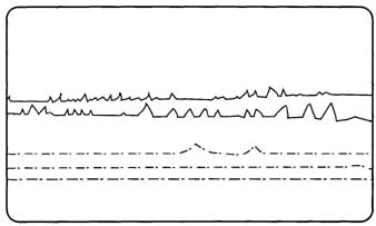
FIG. 11 Interference running horizontally across the picture can be picked
up by cable or the antenna.
Arcing lines can be caused by a defective flyback transformer, tripler unit, or focus control assembly. Check for corona arcs around the outside plastic body of the horizontal output transformer. Rotate the focus control to see if the lines disappear or appear brighter. Replace the defective components that cause arcing in the picture.
A dirty spark gap around the picture tube socket can cause arc-over. Blow out the dust and dirt within the picture tube socket, or replace the socket. If one of these gaps continually arcs over, it can cause an extremely blurry or out-of-focus picture, loss of color, a raster of one color, and chassis shutdown. Check for arcing under the anode BY rubber cap assembly. Sometimes it’s not hooked properly and comes loose causing HV arc-over.
Vertical lines to the left of the picture can result from Barkhausen or improper filtering in the AGC circuits ( FIG. 12). In the early chassis, Barkhausen lines resulted from a horizontal output tube. Today, heavy-firing vertical lines can be caused by the horizontal output transistor or flyback transformer. Shunt small electrolytic capacitors in the AGC and sync circuits for vertical lines in the picture.
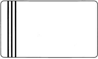
FIG. 12 Vertical lines in the raster or picture is caused by defective
components in the TV chassis.
Body part numbers
Sometimes you can locate the section that the defective component is in by looking at the part number stamped on the top. The large IC part (TA7644BP) shown in FIG. 13 contains the video, AGC, sync, color, brightness, contrast, horizontal, and vertical. Likewise the vertical output IC might have the part number stamped on the body area. Not only will the part number tell you what circuit it works in, but also the correct replacement.

Large IC
Simply look up the part number in a semiconductor manual for the correct universal replacement. You can look at another chassis of the same brand, locate the same IC, and compare the voltage measurements with the other schematic.
For example, if no horizontal waveform is found at the driver transistor, look up the correct pin number on the TA7644BP IC in the semiconductor manual. Check the horizontal waveform at pins 34 and 24. Measure the horizontal supply voltage on pin 33 ( FIG. 14). The supply voltage (VCC) is pin 3 (12 V) Not only have you located the suspected part, correct waveforms and voltage measurements are shown on the replacement linear ICs. Also, correct terminals and part outlines are given in the replacement manual.
Part numbers and letters found on ICs and transistors will help you locate the correct circuit or component, and sometimes the operating voltages. RCA, GE, Sylvania, Workman, and NTE semiconductor replacement manuals cover American, European, and Japanese solid-state devices. These manuals can be obtained from manufacturers, electronics stores, dealers, and mail-order firms.
If the exact schematic is not available, look on another schematic from the same manufacturer using the same part number. Compare the voltage measurements to those of the defective chassis. Sometimes the same part in other brands will have about the same voltage measurements.
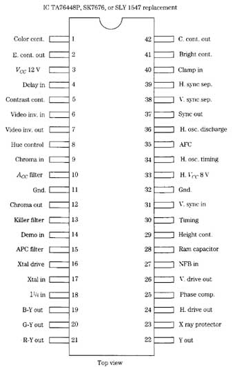 FIG. 14 Cross-reference the part number of the IC using the universal replacement
manual to locate the correct part, circuit, and voltage measurement.
FIG. 14 Cross-reference the part number of the IC using the universal replacement
manual to locate the correct part, circuit, and voltage measurement.
Pills and more pills
For the headache, you can take an Aspirin or r1 to relieve the pain. When servicing a tough-dog problem in the TV, audio, or VCR chassis nothing relieves the pressure or pain until the component culprit is located ( FIG. 15). The tough-dog symptom refers to a very difficult service problem that involves a lot of valuable ser vice time. A tough dog might end up with more than one problem or component in the TV chassis.

Tough dogs are very difficult to locate without a schematic. In many cases, the tough dog is right under our nose. Isolate the symptom to a given section of the chassis and take critical voltage and waveforms. Often, the difficult chassis might have an intermittent component that will only act up once a week or twice a month. These sets should stay in the home until the intermittent state acts up several times a day. Just wait, they will begin to act up more often.
The intermittent chassis can result from poorly soldered connections, intermit tent components, cracked boards, and poor terminal connections. Twist and push around upon the board until you have located the intermittent section. Check all component soldered connections in that area. Sometimes a wholesale soldering up of the entire section might uncover the intermittent connection ( FIG. 16).
A large blob of solder might contain a poorly trimmed component lead. Often, a component lead that is not properly tinned or that solder swill not cling to results in a poor contact. Remove the large blob of solder with a solder wick or sucking tool. Remove the terminal lead. Clean it up and tin the connections. Remount the connection, and solder up.
Intermittent operation in the TV, cassette player. VCR, and audio equipment can be caused with bad sockets or socket connections ( FIG. 17). Poor tuner contacts were caused by a crimped socket, making a poor connection, producing intermittent TV reception in the TV chassis. Check where the socket is mounted upon the PC board for poorly soldered connections. Foil wiring breakage around board stand-offs can cause intermittent operation in the VCR. Inspect the PC wiring around where heavy components—such as tuners, heat sinks, and transformers—are mounted. If the wilt is dropped in shipment or on deliveries, these heavy components can cause cracked PC wiring.
Apply heat and cold applications upon components and PC wiring that are suspected for intermittent operation. Intermittent transistors, ICs, and processors might act up with several coats of cold spray. First apply coolant and spray directly upon the body of the component or parts that require an hour or so of heat-up time. Then apply hot air from an air gun or hair dryer and see if the part returns to the intermittent state.
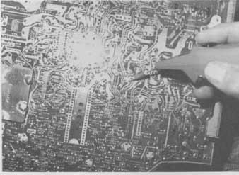
FIG. 16 You might need to solder up every terminal lead in a certain area
before you can find the intermittent connection.
Double-trouble
Here, we are not talking about a chewing gum when two or more components are defective within the TV, VCR, or cassette player. Often the electronic chassis has only one trouble symptom and one defective component. When you repair one problem and another acts up, this is double-trouble. Sometimes you might find more than two defective components in one section of the TV chassis.
For example, a leaky flyback transformer can destroy the horizontal output transistor, isolation resistor, line and B+ fuse, isolation line resistor, silicon diodes, and scan-derived voltage sources in the secondary winding of the horizontal output transformer ( FIG. 18). After repairing the horizontal circuits, the sound begins to cut up and down. So you go to the sound circuits and find a defective electrolytic speaker coupling capacitor. If an intermittent component is found in the double- trouble problem, several hours are needed to repair the defective chassis. Leave that chassis run for several days, making sure that every repair has been completed.
Down under
Look for possible overheated terminals, brown board areas, and poorly soldered connections on the PC board wiring side. These areas will show overheated parts and intermittent connections. Check the terminals on the component side to locate a possible defective component (FIG. 19).

FIG. 17 A poor socket connection on a tuner module caused intermittent
tuning and reception.

FIG. 18 The Il-IVT flyback transformer has separate secondary windings
and provides several dc voltage sources.

FIG. 19 You can locate poor terminal connections by taking voltage and
resistance measurements.
Burned or stripped PC board wiring might indicate defective components, power surge, or lightning damage. Several different blown-off areas of PC board wiring might indicate lightning damage. Often this means the chassis is totaled and complete set replacement is required.
Cracked or damaged boards might be visible by looking closely with a magnifying glass. A strong light above the board, showing light through the board, can help locate fine cracks in PC board wiring. The magnifying circle light is ideal for PC board wiring inspection. Going from terminal to terminal with the low-ohm scale of the digital multimeter (DMM) might help locate open PC board wiring.
Outer space
Check for defective components outside the regular chassis when all other tests are normal. For example, a horizontal white line or no vertical sweep might be caused by an open winding or poor connection of the yoke assembly. Red missing from the raster might be caused by a defective color transistor or R-Y circuit located on the CRT socket board (FIG. 20).
Don’t overlook possible problems in separate boards mounted horizontally above the regular PC board chassis. Poor vertical or horizontal linearity might be caused by defective pincushion parts beyond the regular circuits. Look outside the regular circuits when all other tests fail.
 FIG. 20 The red color was missing from the raster in a Sharp 195B60R portable.
Don’t put it off to tomorrow
The difficult or intermittent chassis may be set aside for several weeks before you attempt to repair it. Callbacks or electronic products returned for the second time can be put off for tomorrow. Tackle these kind of problems at once. Often, the repair and time involved might take less than one hour. Don’t put off it today and do it tomorrow. It might never get done.
When you have repaired a boom-box cassette player for distorted sound and the unit is returned with another problem such as the cassette player is now eating tape, make another charge. Of course, the customer is angry as the repair did not last only for a few days. Any electronic technician knows that the sound distortion problem is a long ways away from the mechanical tape eating symptom.
However, did you clean up the tape heads, capstan, and pinch roller while the player was in for repair? Sometimes we forget to do preventive maintenance. A good clean-up and a thorough preventive maintenance check-off can save a lot of headaches. Besides a good clean-up, one should check the type of cassettes and also the condition of the suspected cassette, which might be defective. The customer is never wrong, but he or she might not know how the cassette operates or might mishandle the cassette.
Time, precious time
Time is one of the most important factors for the electronics technician. Time marches quickly when you are stuck with a difficult problem and no schematic. It might take months to receive the correct diagram, and sometimes you might never receive a schematic for some older products. Wasted time is wasted dollars.

FIG. 21 The cassette and boom box player might take longer to repair for
some TV technicians.
Servicing a radio or stereo chassis might require more time to repair for a TV technician ( FIG. 22). Some were not trained for audio-type service. Time can be wasted and never recovered when working on a tough-dog problem. In the following pages, I hope to reduce the time that it takes you to troubleshoot and repair consumer electronic products without a schematic.
Test points
The manufacturer has placed into the schematic several test points for easy servicing. These test points are for taking waveforms, signal tests, and voltage measurements. The test point might consist of a lug, spot, or raised area that any test instrument can be connected upon the chassis.
The test points within the CD player provide quick attachment of the scope for troubleshooting and making critical adjustments. Test points are found throughout the camcorder circuits for adjustments, waveforms, and testing procedures. The test points in the TV chassis might be located in the video, RF/SIF, auto kinnie bias, and CPU circuits ( FIG. 23). Clip the scope to the video test point to determine if the front-end circuits are functioning. Measure the RF AGC voltage at the test point fed to the tuner and IF AGC test point to determine if the AGC and IF circuits are working.
If the TV chassis has an MPX/stereo sound system, you can find test points throughout the stereo IC circuits. The test point at the VCO pin terminal (32) is to set the VCO adjustment control ( FIG. 24). A SAP BPT out pin terminal 6 (TP606) can scope the SAP circuits. The multiplex input pin terminal (1) might have a test point (TP603) to determine if audio is found at the input terminal. A SAP level control has a test point to adjust the voltage at snap level detector. Many test points are placed throughout the electronic circuits to make signal checks, voltage test, and critical adjustments.
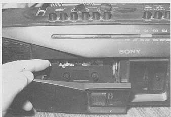
FIG. 22 A dirty tape roller can cause a call-back when preventive maintenance
is not rendered while making other repairs.
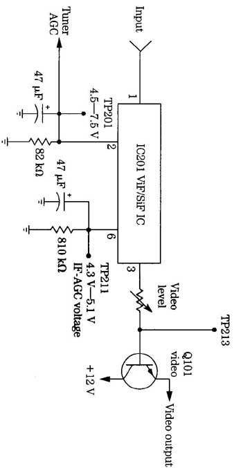
FIG. 23 Look for various test points or tabs when there is no video in
the tuner or IF section of the TV.
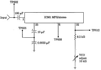
FIG. 24 The different test points or tabs are used to make critical adjustments
within the MPX/stereo section.
Say it isn’t so
Have you ever checked the electronic chassis, ordered out a new part, waited for the new replacement, installed it, turned on the switch, and the results are the same? This just cannot happen after installing a new IC component. Look at all the time lost in removing the old IC and installing the IC replacement. Except this can happen to the best electronic technician when all components tied to the terminal of the suspected IC are not thoroughly checked ( FIG. 2

FIG. 25 Always check all components and circuits tied to each pin terminal
of the suspected IC before replacement.
What if the voltages measured upon each pin terminal of an IC were quite normal with a fairly normal input signal and no output waveform? Even the supply voltage (VCC) was quite normal. The IC just has to be defective. You install a new IC after removing the old one and cleaning up each PC terminal connection. The results were the same: no output signal.
So, you again make voltage, resistance, and waveform tests. Everything appears normal. Maybe a piece of foil was cracked or broken. All terminal pins are soldered up again. Resistance tests were made from pin terminal to a common point on the same PC foil. All tests were good. What went wrong?
No doubt, the new IC replacement was defective. However, this never happens, as you test every component before installing for this same reason. Of course, it’s difficult to test the IC with so many terminals. So you just install it and take a chance. Nine times out of ten, you never have to replace a replacement. These operations just happen in the life of an electronic technician. Always test each component be fore installation.
Ten points of servicing
Where do you start when servicing a TV, stereo, or VCR chassis? Start with the symptoms provided by the electronic product. In the TV chassis, use the symptoms found on the TV screen and speaker. An insufficient vertical raster indicates trouble in the vertical section. Pulled width might be caused by the low-voltage power sup ply, horizontal circuits, or pincushion circuits. Intermittent sound might be caused by a defective audio IC.
Start with the symptom, and isolate the defective component. Break the circuits down, and list the probable circuits the defective part might be in. Then make voltage, resistance, and solid-state tests in those circuits to locate the defective part.
To locate the defective section, you must know where they are located on the chassis without the help of a schematic. For example, if a tape player has weak and distorted sound, with normal AM and FM stereo reception, the audio frequency (AF) and audio output circuits are normal ( FIG. 26). The defective component must be between the tape head and the stereo function switch. The most obvious things to check are a dirty tape head, electrolytic coupling capacitors, pre-amp transistors or ICs, and the supply voltage to the tape head circuits.
Locate all large components on the chassis to find the defective circuits. Around large filter capacitors are the low-voltage power supply components. Look at the large transistors or IC audio output components for defective sound circuits. Vertical circuits are nearby when locating the vertical output transistors. The horizontal output transistors and regulators might be found on a large separate or chassis heat sink. Try to locate large parts in each section that point to the correct symptom.
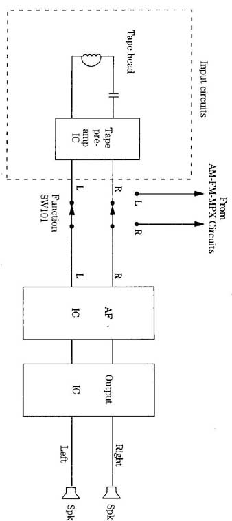
FIG. 26 Isolating the input circuits of the tape cassette player can solve
the weak and distorted audio problem.
After locating the defective circuits, take voltage and resistance measurements. Some technicians check solid-state parts first. The most accurate instrument for taking voltage and resistance measurements within the solid-state chassis is the DMM ( FIG. 27). Voltage and resistance measurements less than 1 V or 1 ohm are required within the solid-state chassis. Accurate base bias voltages (0.3 to 0.6 V) between base and emitter terminals not only indicate if the transistor is good, but if it’s a germanium or silicon type.
Next, scope waveforms are needed to signal trace the various circuits. When the horizontal output circuits are functioning, the horizontal waveform can be traced from the vertical oscillator, amp, and output to the vertical yoke winding. Low distortion can be found in the stereo circuits with a sine or square wave at the input. Scope the audio stages for clipping and distortion.
After several tests, the defective part must be removed from the circuit. Desoldering equipment and solid mesh or wick material can be used to remove excess sol der. Be careful when removing transistor pins so as not to pull or pop off thin PC board wiring connections. Too much heat might dislodge or destroy small PC board wiring. The controlled electronic soldering system or station is ideal for removing and replacing PC-board-mounted components ( FIG. 28).
Check the suspected part after it’s removed from the cha Sometimes the intermittent transistor might be normal after heat is applied and it’s removed from the circuit. Replace it. Transistor, continuity, resistance, and special equipment tests might indicate a defective part after removal.
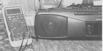
FIG. 27 This Fluke DMM is ideal for taking critical voltage, resistance,
and current measurements within the electronic chassis.
Test the new component before installing. Check transistors, capacitors, resistors, choke coils, diodes, and zener diodes before installing them. Make sure they are good before soldering. By checking the part before installation, you might save a lot of valuable service time and confusion.
Install the new part with careful soldering of the terminals. Too much solder can overlap between terminals and short out the component when the chassis is turned on. If too much heat is applied, it might damage a semiconductor. Clean out all solder and rosin flux between terminals.
Double-check all terminals. Are they all placed on the correct PC board wiring? Remember, the transistor or IC component can be soldered with reversed terminals. Check the wiring connections. Make sure no cold joints or interconnected connections are made. Check and double-check before turning on the chassis.
The following steps must be taken to locate, isolate, repair, and replace a defective component:
1. Check the symptoms.
2. Isolate the circuits.
3. Locate the part.
4. Take voltage and resistance tests.
5. Perform scope tests.
6. Remove the defective part.
7. Check the defective part.
8. Test the new part.
9. Install the new part.
10. Clean up and double-check.
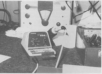
FIG. 28 The electronic controlled soldering iron is ideal when removing
and replacing components in the electronic chassis.
Yesterday’s hero
You have just serviced a tough dog that two other electronic shops could not fix, the customer is happy, you are elated, and in comes another one a week later. Tough dogs seem to come in bunches. One week you are loaded down with difficult repair jobs, and the next month you get hardly any. So you go to work, roll up your sleeves, and begin again.
Of course, this case is a little different. You have never seen a TV chassis like it before, you have no schematic, and you just know parts are not available. The TV set might act up once a week and then play normal for several months. In fact, the symptom is intermittent operation and chassis shutdown. You let it sit there for several days. This morning, you feel great, and the tough dog is in for a rough time.
Just about any component in the TV chassis can cause shutdown ( FIG. 29). The back cover is removed, and the chassis operates normal with a very nice color picture. The only thing to do is to let it rim until it quits. You come back from lunch, and it’s still running. Every once in a while, you look at the picture while servicing other electronic units. After nine days. the screen goes black.

FIG. 29 Check for a voltage regulator IC and horizontal output transistor
upon the TV chassis for chassis shutdown problems.
Check the horizontal and low-voltage power supplies because most shutdown cases occur in those circuits. Carefully look over the chassis for the horizontal output transistor and line-power supply regulator. Take a critical voltage test upon each component. No voltage was found at the horizontal output collector terminal located on a heat sink, and no voltage out of the regulator IC was found upon a separate power board. A large flanged heat sink upon a separate board held an IC that looked like a regulator and power transistor ( FIG. 30).
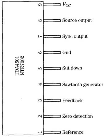
FIG. 30 The regulator (SMPS) IC upon the heat sink can be determined by
the number upon the part and checking in the replacement manual.
The power IC number TDA4601 was checked in the NTE universal semiconductor replacement manual as an NTE 7002 regulator. The manual listed the IC as a switched-mode power supply control IC, working at 15-V source, which meant a power transformer and power transistor must be close by. The switched-mode power supply (SMPS) transformer was found on the same board, Voltage measurements upon the transformer winding indicated 167 V, which no doubt fed to the SMPS driver or power transistor. The voltage upon the power transistor bolted to the same heat sink had 167 V to the collector terminal. No voltage was found on the base or emitter terminals.
When the voltage probe touched the base terminal, the TV chassis came alive. At first, the power driver transistor was suspected and tested normal. Now a negative voltage (-1 V) was found at the base of the power transistor. The chassis was shut down, and the PC wiring at the base terminal went to pin 7 of the IC regulator. All voltages were now tested at each pin of the SMPS regulator ( FIG. 31). A scope waveform at output pin 7 represented a square wave around 2V.
The scope probe was attached to the base terminal of the power driver transistor to monitor the SMPS waveform with the DMM testing the supply voltage source at pin 9. When the chassis shut down again, all voltages upon the regulator IC were very low, except pins 4 and 5, which had high voltage. All components led to the pin terminals of the regulator IC were tested and appeared normal. Perhaps the TDA46O1 regulator was breaking down under load.
 FIG. 31 The switch-mode power supply (SMPS) IC can be monitored with the
scope arid DMM.
FIG. 31 The switch-mode power supply (SMPS) IC can be monitored with the
scope arid DMM.
Because there was no collector voltage at the horizontal output transistor (measured 121V), no waveform upon the base of power drive transistor, and high voltage (167V) on the collector of power SMPS transistor, the IC voltage regulator was suspected of breaking down or going open. After the TDA4601 regulator IC was replaced, the TV chassis has been operating ever since. With previous experience from the RCA and Sylvania SMPS power supplies, no 120-V source applied to the horizontal output transistor, helped solve the foreign TV chassis, without a schematic.
Loss of life
Excessive lightning damage or power outage can destroy a TV set, VCR, receiver, and cassette player. Extensive damage to the low-voltage circuits and tuner in the TV can total out the entire chassis ( FIG. 32). When the 220 neutral wire breaks before entering the home, it can place extra ac voltage upon any electronic chassis. High-line voltage wires touching one another can result in high-power out age.
A TV set exploding and starting a house fire can be very dangerous and fatal to the homeowner. If the fire spreads to the window curtains and spreads to other rooms, someone can be trapped in the raging house fire. Houses can be rebuilt, but a loved one is lost forever.
The electronic technician should always be careful when servicing the electronic chassis. Replace all safety marked components with exact replacements. Never replace a flame proof resistor with a carbon resistor. Replace all Erie-power supply and horizontal circuits with correct components. Make sure that cables and wires won’t lay upon hot components in the chassis. Inspect and replace the defective power cord.
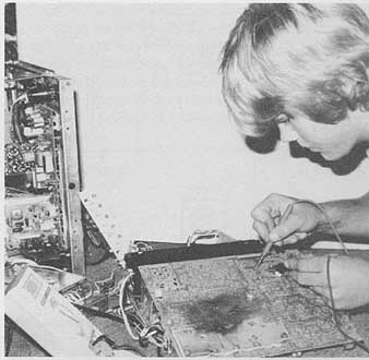
FIG. 32 When lightning damages the TV set, the chassis might have to be
totaled out instead of repaired.
Don’t drop metal screws and small metal parts down into the maze of wiring and components, then forget to remove them before buttoning up the chassis. Make good, clean soldered connections. Blotched bare wiring and lousy soldered connections might give the fire department and state commission an excuse to blame the electronic technician. In case of a death, you might lose everything you have worked for. Be careful out there.
Also see:
Repairing the deluxe amplifier
. ===