Today, VCRs come in many different electronic products. You may find a VCR by itself or within a CD/VCR combo, a DVD/VCR combo, a DVD/VCR recorder, a DVD/VCR home theater, a CD/DVD/VCR combo, or a TV/VCR combo. Recently, VCRs have been placed within 9-, 13-, and 19-in TV chassis. Now a VCR can be found in a 27-in flat screen TV with a built-in DVD player (Fig. 1).
Although VCR repair can be quite difficult without a schematic, there are a lot of mechanical and electronic problems that can be solved without one. Mechanical problems can be seen, felt, and heard, whereas electronic symptoms may require added ser vice time. Note the electronic problem, and isolate and locate the defective component.
Look for defective integrated circuits (ICs) and transistors that can produce a number of electronic problems. IC and transistor parts cause most service problems in VCRs.
Locate the ICs and transistors that are tied to the various parts. Leaky and over heated ICs can be located by touch and with critical voltage measurements. Case histories may help to solve other VCR problems. Record each case history for future reference. Remember, several VCR brands may be the same inside.
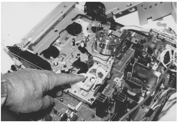
FIG. 1 The VCR chassis is found mounted ahead of and on the same printed
circuit (PC) board as the TV in a 13-in Panasonic TV/VCR combo.
What are the symptoms?
You must know the symptoms of the VCR before you can look for defective components. How does the VCR operate? A dead or intermittent speed problem may be the result of a bad drive motor. Poor VCR loading may be caused by a jammed cassette assembly or a bad loading motor circuit. When the VCR eats tape or spills tape out, check for a bad clutch assembly, erratic takeup reel, or a bad friction gear, and on it goes. Check the symptom, and apply it to the correct section within the VCR.
You can compare the symptom with a block diagram or another VCR case history when a schematic or service literature is not available for a particular VCR model. Compare the VCR problem with those of other VCR models and schematics. Several symptoms can be caused by a common defective component within both play and record modes. You may find that the VCR chassis before you is the same as a schematic in the file cabinet.
SLOW LOADING, SYLVANIA
The cassette loading was slow, and then the machine would eject in a slow manner and would shut off before the tape was ejected in a Sylvania VC4510 VCR. Since the capstan motor provided loading, voltage checks on the motor driver IC (IC2005) and main capstan coil drive IC (IC2004) were taken. The voltage was down to 7.1 V and should be around 14 V. Tracing the 14-V source back to the power supply and to D1006 revealed that the circuit was still low in voltage. D1015 tested normal. C1012 (330 uF) and C1013 (330 uF) were tested on an equivalent series resistance (ESR) meter and were replaced to solve the problem (Fig. 2).
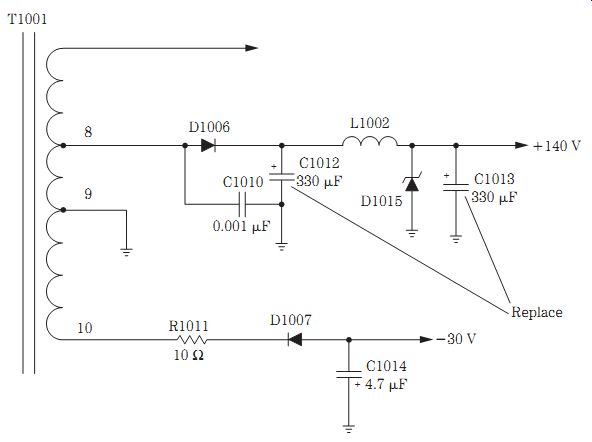
FIG. 2 Replace the C1012 (330- uF) electrolytic for slow loading in a Sylvania
VCR4510.

FIG. 3 Clean the tape head by moving the chamois stick horizontally across
the rotating cylinder.
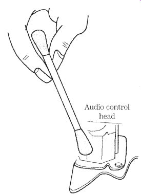
FIG. 4 Clean the audio tape head with alcohol and a cleaning stick.
VCR cassette problems
The VCR cassette itself may be cracked or broken and will not load properly. Sticky substances on the tape can cause it to become jammed or spill out. The tape may record in a loose fashion and, when played, may eject or pull out, with excess tape from the cassette. Dry or worn wheel tabs within the cassette can cause slow and erratic speeds. A bad cassette holder may cause the cassette to jam or prevent loading of the tape. Try another cassette to determine if the cassette is defective. Unraveled tape inside the VCR may have to be cut loose to remove the cassette.
Head cleanup
The video head surface should be cleaned with a chamois skin stick. Clean the tape head horizontally with a cleaning stick or tab. Do not move the stick up and down because you can damage the head. Throw away the dirty cleaning stick after cleanup. Each time the VCR appears on the service bench, clean the tape head and tape path components. The tape head can be cleaned with isopropyl alcohol and a cotton swab (Fig. 3).
Dirty tape heads can cause a loss or deterioration of the video signal. Video dropout and audio distortion can result from a clogged tape head. Some manufacturers have included automatic head cleaning systems in their machines. Clean the tape heads, guides, rubber pinch rollers, and threading mechanism of oxide. These surfaces can be cleaned with wet, dry, or magnetic systems.
Audio head cleanup
Clean the audio control head in the same way. Move the cotton swab back and forth on the head. Wipe off all tape guides and rollers with a swab dipped in alcohol to clean the tape running path (Fig. 4).
Be very careful not to damage the upper drum and other tape running parts. Clean the head horizontally, not vertically. Wait until the head area is dry before operating the unit to prevent tape damage. A dirty audio tape head may cause distorted, intermittent, or no sound.
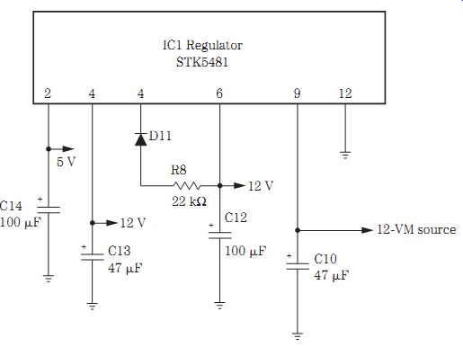
FIG. 5 Replace regulator IC1 for an improper 12-V source that feeds the cassette
motor in a Zenith VC-1820 VCR.
Loading motor problems
Go directly to the loading motor and housing bracket assembly when the cassette will not load. The defective loading motor may be open or become erratic in rotation.
Bad brushes in the dc motor can make the motor not run, resulting in a no-loading symptom. The defective loading motor may be erratic in rotation. Slow tape loading can be caused by a bad loading motor. Intermittent tape loading also can result from a defective loading motor.
Measure the voltage across the loading motor terminals. Suspect a loading motor IC when no voltage is found at the motor terminals. Check for defective silicon diodes in the loading motor driver IC voltage source. Check for small 3.7- to 3.9-ohm resistors in the voltage source when the motor will not rotate. A bad 5.1-V zener diode in the power voltage source can prevent tape loading (Fig. 5).
The defective loading motor may spin the head for a few minutes and then shut off. Check the loading motor and mode switch when the VCR begins to load and then shuts off. A defective loading motor or binding load assembly can cause a slow loading symptom. Replace the pulley and loading motor belt when slippage occurs and the cassette will not load. Check for a bad bracket assembly when the VCR tries to load and ejects the tape. Check the cassette load or in switch when the tape will not load.
Besides a defective loading motor, a defective loading cam can result in a VCR that will not load a tape. Check for a broken motor belt or a jammed gear when the loading motor will not load the tape. A bad front-loading gear may prevent loading of a cassette. Replace the rotary switch when there are loading problems. Inoperative cassette loading can be caused by a bad mode switch. Replace the eject gear and side plate when the cassette will not load or eject. In a JVC HRO152U VCR, the tape would not load even with a new belt, and this was caused by hardened lubricant on the cam assembly.
LOADS, THEN SHUTS DOWN
Suspect a bad loading motor when the tape loads slowly and the machine quits in the middle of loading the tape. Check for a defective loading motor when the head spins for a few seconds, and then the unit shuts off. A bad cassette down switch can cause inoperative loading, immediate tape ejection, and play if the tape is loaded manually.
Look for a bad cassette holder when the cassette jams on loading.
Check for a bad electrolytic capacitor in the voltage source of the loading motor and driver IC when the VCR shuts down after loading. Suspect a servo IC when the tape loads and the unit shuts off. Monitor the supply voltage when the tape tries to load and the unit shuts off; this is caused by a defective transistor or IC regulator. The bad loading motor IC can cause the tape loading to lock up and the unit's power to go off. The VCR shuts off when loading is caused by a capstan B+ control transistor. Replace IC2001 in an Emerson VT0950N VCR when the unit shuts down after loading.
A bad mode switch can shut the VCR off when it is in the loading mode. When the loading motor is rotating, squeals, and then shuts off, this can be caused by a bad mode switch. Look for a bad end sensor when the cassette will not load or accept tape. Suspect a defective loading cam gear when the unit locks up during the loading process.
Check for a bad sensor when the tape loads and right away unloads.
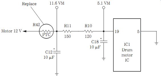
FIG. 6 Defective drum motor regulator IC1 was replaced in a JVC HR-D170U
VCR that tries to start up and then shuts down.
STARTS TO LOAD TAPE, SHUTS DOWN
The tape starts to load around the drum and then unloads in a JVC HR-D170U VCR, and the unit shuts down. A quick voltage check was taken on the drum mo tor drive IC1. The supply voltage should be around 5.1 V and was near zero. The 5-V source is taken from an 11.6-V source. R11 and R10 checked normal in the voltage source. The 5.1-V zener diode tested normal in the circuit. C12 and C16 checked normal with the ESR meter. IC1 was replaced with another AN6671K IC component (Fig. 6), thus clearing the problem.
Power-up problems
Suspect a bad voltage regulator when the unit powers up and then in 3 or 5 seconds has no functions at all. Check for a bad electrolytic filter capacitor in the power sup ply for a bad power-up symptom. Check for a defective 12-V zener diode when the unit powers up and then shuts off. Check the main filter capacitor (470 uF) for no power-up when the unit is cold and the LED blinks. A shorted or leaky electrolytic on the switch 5-V line can cause the unit to power-up at once and then shut down.
Check all electrolytics with the ESR meter.
The dead chassis with no power-up symptom can be caused by an open fuse in the power supply. A defective transistor regulator in the 5-V source can produce a dead symptom. Check for a defective transistor switch circuit in the power supply for a dead and no power-up symptom. A defective 12-V regulator in the power supply can cause no power-up, a display light, and no cassette loading. A dead unit with no power-up can result from a shorted or open line voltage regulator IC. Shorted or leaky diodes in the power supply can cause a no power-up symptom. Suspect low voltage to the main microprocessor or system control IC for no power-up. Replace an open power transistor regulator when power shuts off in 2 seconds.
Check for a bad end sensor when the unit powers up, tries to load the tape, and sometimes operates. Replace the end sensors if the unit powers up and then shuts off.
A bad 4.19-MHz crystal can cause power-up inoperative with flashes in the display and power supply voltages normal. If the VCR power-up supply reels rotate for 10 seconds and the loading motor runs all the time, this can be caused by a bad cam switch assembly. A bad mode switch can cause the supply reel to rotate counterclockwise with the guides fully loaded and then to shut off. Replace the cassette up and down switch when the unit powers up, turns to load, and then shuts off. A bad LED on the mode printed circuit (PC) board can cause a power-up and an attempt to load the empty tray. Replace resistor R2 (680 kilohm) off of Q1001 in a Magnavox VR8520 VCR when the unit powers up, the cylinder spins, and the unit loads with a squealing noise.
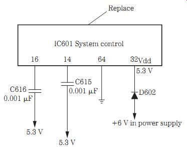
FIG. 7 No power-up in an RCA VR250 VCR was caused by a defective system control
IC601.
NO POWER-UP, RCA
An RCA VR250 VCR would not power up. Critical voltage measurements were made in the power supply and on the main system control microprocessor (IC601). The supply voltage source was 1.1 V on pin 32 (5.3 V). At first, the 5.3-V source was suspected of being low at the power supply source. The 5.3-V source is fed to the data pin (Vdd) of IC601. The 5.3-V source is derived through D602 from a 6-V source in the power supply. A supply of 6 V was found on the anode side of D13 and 1.1 V on the collector side. D602 checked normal in the circuit. When pin terminal 32 was removed from the PC wiring on pin 32, the voltage returned to around 6 V. Replacing the shorted system control IC601 solved the problem (Fig. 7).
Speed problems
A cracked or a loose capstan belt can cause a slow speed problem. A stretched, loose, or shiny and smooth loading belt can produce slow speeds. Suspect a defective capstan motor for slow speeds. A dry flywheel bearing with hardened grease can cause slow speeds. Clean out the capstan bearings and re-lube. Suspect a defective brake arm for slow speeds. A dirty brake pad can cause a slow speed problem.
Check for a bad IC regulator feeding the capstan motor circuits for slow speeds. A bad transistor regulator in the 5.8-V source can cause the capstan motor to run slow. A low-voltage IC or transistor feeding the capstan supply voltage also can cause slow speeds. Check all electrolytics within the power supply source for improper capstan motor voltage. Slow drum speed can result from a bad drum driver IC. Look for an open resistor or a change in resistance in the small-ohm resistors (2.2 ohms) in the power source. A bad servo IC can make the capstan motor run slow.
A speed that is too fast also can be caused by a defective capstan or drum motor.
Check for poorly soldered joints on the motor terminals. Suspect a loose magnet inside the capstan motor for fast speeds. Check for poorly soldered connections on the capstan drive IC. Replace a defective capstan control transistor for fast speed. A bad plastic E ring on the capstan spindle can cause variably slow or improper speed. Resolder the PC board around the drum stators when the capstan motor runs fast and shuts down occasionally. Replace the mode switch for fast speeds.
Check the electrolytics in the power supply and servo circuits when the cylinder motor runs too fast. A bad cylinder or capstan motor can produce fast speeds. Resolder all connections around the drum motor for fast-speed symptoms. Replace the motor driver IC for fast speeds. Check the 4.19-MHz crystal when the drum spins at a high speed. Check bypass capacitors (0.047 uF) in the servo circuits for capstan fast speeds.
Erratic functions and uneven speeds can result from a bad motor. Erratic speed can be caused by a defective motor driver IC. Check the voltage regulator IC when the capstan rotates erratically. Check for defective capacitors in the voltage supply of the capstan motor. Suspect all electrolytics in the voltage supply source, and check them out with an ESR meter. Do not overlook the 3.58-MHz clock data when the capstan and cylinder motor are erratic (Fig. 8).
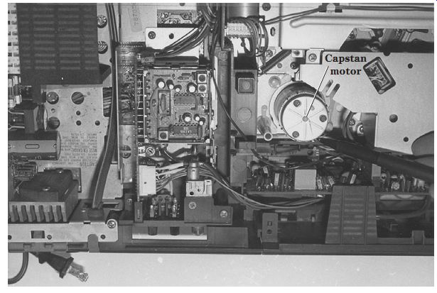
FIG. 8 Check the capstan motor for erratic or intermittent rotation of the
tape.
Wow and flutter
A bad or oily belt can cause a wow and flutter condition. Check the capstan motor when wow and flutter occur. Clean out the old grease from the capstan bearings, which can provide a drag, wow, and flutter sound. A bad clutch assembly and idler can cause wow and flutter. Replace the bad clutch assembly in a Hitachi VT1310A VCR for wow, flutter, and audio drags.
Dead, no operation
Check for an open or blown fuse when a VCR is dead. Shorted or leaky diodes can cause a dead, no-operation symptom. Defective diodes and transistors within the power supply regulator system can cause a dead chassis. A defective system control and servo IC can cause a dead chassis. Poorly soldered connections can be found with an ESR meter. Suspect blown parts or PC wiring traces due to lightning or a power surge when the chassis is dead. Leaky silicon and zener diodes in the power supply can result in a dead chassis.
The dead, no-function symptom can result from a bad sensor lamp. Check the mode switch when the chassis is dead. Suspect a defective side switch for a dead loading operation. No power-up, no display, or the tape loads and plays and then ejects can be caused by a bad connection at PMT01 on the main PC board. Check for bad fusible resistors in the power supply when the chassis is dead and there is no display or function operation. A bad power transformer can cause a dead, no-function symptom.
Check all electrolytics for a dead power supply.
Check for a bad silicon diode on the 5-V line when there are no functions and no tuner action but the display lights up. No power-up and no function display may result from a faulty 4-MHz crystal resonator. No power-up and a flashing display can be caused by a faulty 4.19-MHz crystal on the tuner PC board. Suspect a faulty 220- to 270- uF electrolytic for a dead chassis and no display. A bad diode in the power supply can cause a dead, no-display, fuse-okay symptom. Suspect small open resistors in the power sup ply source for a dead, no-rotation symptom.
DEAD, NO POWER-UP, NO OPERATION
A Magnavox VR9040 VCR came in with a dead, will-not-power-up symptom. Very little voltage was found on the system control microprocessor (IC6001). Tracing through the different connections and wiring to the power supply revealed that a 1.5-A fuse was open. At first, the fuse looked and tested good. Replacing the open fuse in the 5-V power source solved the problem (Fig. 9).

FIG. 9 An open fuse caused a dead chassis, no-power-up symptom in a Magnavox
VR9040 in the standby power supply.
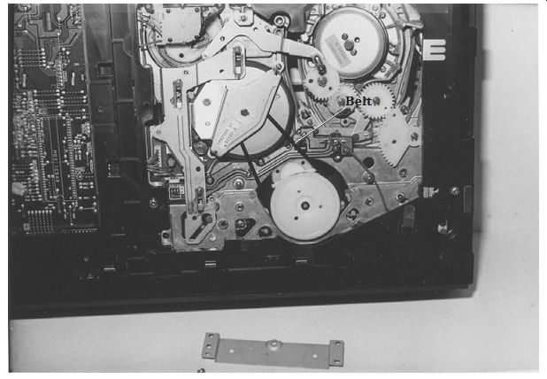
FIG. 10 A loose or dirty belt or oil on the belt of a loading or capstan
motor can cause erratic or slow speeds.
Time to replace the belt
Loose, worn, or broken drive belts can cause slow or improper speeds in VCR functions. Check all belts for shiny surfaces, cracks, or broken areas. A shiny belt indicates slippage around a capstan motor pulley. Check the drive belts and wheels for erratic or intermittent movements. Clean the belts when cleaning the tape heads.
Replace the belts with original part numbers, when available. Universal belts and drive wheels can be ordered from local or mail-order firms. Sometimes exact drive wheels, idler pulleys, pinch rollers, and VCR gear assemblies can be obtained from large mail-order firms. Several VCR belt kits from different manufacturers offer convenience, economy, and a wide range of replacement parts. Pick up a belt gauge for a quick, accurate method of measuring the thickness, width, and inside circumference of broken or worn belts. Clean the motor pulley, cylinder, and belt in a Hitachi VTM1371 VCR for poor speeds and slow rotation (Fig. 10).
The tape eater
When the tape spills out and the take-up reel slows down, suspect a loose belt, a dry take-up reel, or a frozen bearing. A dirty tape head or a sticky roller or spindle can cause the tape to spill out. A bad or sluggish reel motor can cause a tape-eating symptom. Check the pinch roller bracket when tape pulls out in the playback mode.
Replace the reel brake assembly when the VCR eats tape with a new idler, belts, and pressure roller. In the fast-forward mode, if the VCR eats tape and the fast-forward rewind is intermittent, replace the clutch-idler assembly. Chewed-up tape and intermittent symptoms can result from a bad brake assembly. A bad clutch-bearing binding can result in chewed-up tape.
Check the capstan motor and a possible cracked pulley when the VCR eats tape and does not eject the cassette. Replace the capstan motor when the motor runs back ward and pulls out tape. A bad cylinder motor stator assembly can cause the VCR to eat tape in all modes.
Improper reel rotation can be caused by a bad driver reel motor IC and result in tape spilling out. The bad motor driver IC in take-up mode can spill out excess tape.
A defective loading IC on the take-up reel in an RCA VLT900 VCR shuts the unit down in a few minutes and causes the unit to eat tape and the reel to remain stationary.
Replace a cam stopper when the tape pulls out and the power goes off. A stripped motor pulley can pull out the tape. Replace a broken idler gear spring with a clicking noise when the unit eats tape. Check for a bad capstan motor stator assembly when the tape pulls out in all modes of operation. Cut off the excess end of the spring near the take-up reel when the unit shuts down after running for several hours and begins to eat tape. Suspect a bad idler when the take-up reel is inoperative, there is no fast forward or rewind, or the tape pulls out. A bad carriage assembly that is slightly out of line can produce a rubbing sound heard in fast forward or rewind and result in the unit eating the tape. Pulling of tape can be caused by a bad friction gear and transmitting arm assembly.
Replace the idler, belts, and capstan motor when the unit shows intermittent operation and then spills out tape. Replace the capstan motor, idler, and belts when the VCR eats tape intermittently. The tape was damaged in a Zenith VR1820 VCR as a result of a bad tension spring (809-1992).
Cylinder and drum motor problems
The cylinder motor drives the video heads at the required speed, and servo problems affect the quality of the picture. Check voltages on the cylinder drive motor IC and applied to the motor terminals. Locate the motor driving the video heads or drum assembly at the bottom of the unit, and take continuity test measurements.
A bad relay can cause no rotation of the cylinder or capstan motors. Resolder all cylinder and capstan PC board connections if the motors are not working or are intermittent, and then replace the drum stators. Check for improper voltage to the cylinder motor circuits caused by a shorted electrolytic in the power supply. Replace both end sensors that are open after the tape loads, the cylinder does not rotate, and then the unit shuts down. Replace the lower half of the cylinder when the tape loads, retracts, and then the cylinder does not rotate. Check for bad connections at the drum motor when the tape loads and there is no drum rotation. Suspect open small resistors in the voltage source when the cylinder motor does not rotate (Fig. 11).
A bad cylinder motor IC can cause the capstan motor to stop rotating. Replace the cylinder motor IC when the VCR powers up, the cylinder spins continually, and the unit shuts off. Check for a bad servo IC when the drum is inoperative. Replace the cylinder or drum motor IC when the cylinder does not rotate. Check the voltage regulator IC when there is no cylinder movement.
An open transistor voltage regulator in the power supply source can cause the cylinder motor to remain stationary. Check for badly soldered joints at the transistor voltage regulator when the capstan does not rotate. A bad zener diode regulator can cause the cylinder motor at power-up to shut down in play mode. Check for a defective diode in the cylinder circuits when the cylinder motor becomes intermittent and stops in play mode. The cylinder or capstan motor may not run with a bad end lamp.
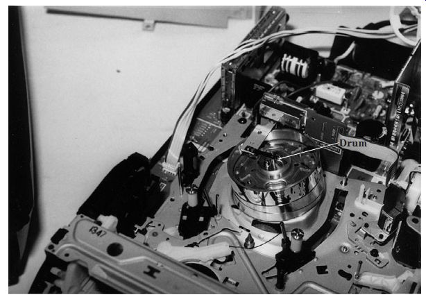
FIG. 11 Check for a bad servo IC when the drum or cylinder does not rotate.
When the cylinder motor runs fast and then shuts down, suspect poorly soldered joints on the motor stators. Replace a drum that shows irregular speeds. Check for a bad 100- uF electrolytic in the power source when the cylinder runs too fast. Suspect a defective electrolytic in the servo circuits when the drum motor runs fast all the time.
Check all the electrolytics in the power source when the cylinder runs all the time with no other functions. Test all diodes in the power source when the cylinder runs too fast.
A bad servo IC can make the cylinder run too fast. An intermittent voltage regulator IC can cause erratic speed of the cylinder motor. Replace the 4.19-MHz crystal when the drum spins at a high rate of speed, there is no display, the LED lights up, and the cassette is inoperative.
SPEED JUMPS, COLOR FLASHES, PHILCO
The symptoms in a Philco VT3010A01 VCR were speed jumps, color flashes, and a sound like that caused by a bad cylinder bearing. The cylinder motor voltage source that feeds the cylinder assembly and driver IC checked okay. The 5- and 4-V sources were low. On checking the power source components within the power supply, the electrolytics were tested with an ESR meter. All diodes checked okay with the diode tester of a digital multimeter (DMM). C1017 (1000 uF) in the 5-V source and C1013 in the 14-V source were replaced (Fig. 12).
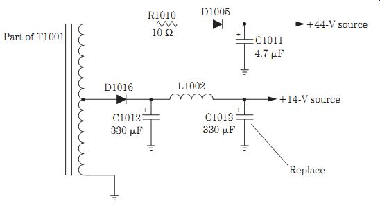
FIG. 12 Replace C1012 (330 uF) and C1013 (330 uF) for speed jumps, color
flashes, and a sound that resembles a bad cylinder bearing in a Philco VT3010AT01
VCR.
Capstan motor problems
The capstan motor provides tape motion in play, record, and fast-forward modes.
The capstan motor is driven by a drive speed and system control IC. No tape motion can be caused by a defective capstan motor, drive belt, driver, or servo IC. Check for supply voltage at the driver and system control IC. Measure the voltage applied to the motor terminals during play mode.
Suspect a bad capstan motor when it will not rotate and voltage is found at the motor terminal. A dead VCR with a blown fuse can be caused by a defective capstan motor. A bad capstan motor will not operate in playback, record, fast-forward, or rewind modes with a blown fuse. The shorted capstan motor can cause parts in the power sup ply to become hot and smoke. Check for bad capstan motor bearings when the capstan motor will not rotate and the motor appears frozen. A bad capstan motor can cause the tape to load halfway and then eject, and the reel table will not turn. Replace D108, D109, and D110 in a GE VG2010 VCR when the capstan motor will not run. A defective end lamp can keep the capstan motor from operating. An open 2.2-ohm resistor feeding the capstan motor keeps the motor from operating.
Check for an open drive motor IC when there is no rotation. Check for a bad fuse and servo IC when the capstan motor will not rotate. Suspect a bad transistor voltage regulator feeding the drum motor IC. Replace the IC voltage regulator when the capstan is inoperative in play mode and shuts down. The capstan motor will shut down with badly soldered connections on the transistor voltage regulator.
A bad capstan motor can result in no tape rotation and no frequency generator (FG) pulse. Replace the capstan motor when there is no FG pulse from the motor and no motor rotation. A bad capstan motor can cause the cassette to get stuck inside, the unit to not play or eject the cassette, or the unit to not load or eject. Replace a defective capstan motor when there is a jerky motion in play mode and it looks like a bad bearing.
A bad capstan motor also will not let the VCR rewind.
When the capstan motor will not rotate, check for a bad motor or a defective Hall sensor in the motor assembly. A defective capstan motor can cause the tape to load halfway and then eject and the reel table to remain stationary. The capstan motor in a Sony VCR has no rotation and eats tape, and this was caused by resistor R506 (1 kilohm) from CN1-4 to IC502-72 on the bottom of the PC board.
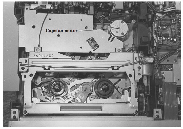
FIG. 13 A bad capstan motor can operate at fast speeds.
CAPSTAN RUNS FAST
Check for a defective diode in the power source with the diode tester of a DMM when the capstan motor keeps rotating very fast (Fig. 13). Check for bad diodes in the power source when the capstan motor is intermittent in start/run mode. A bad capstan motor also can operate at fast speeds. A bad capstan motor can cause the tape to run at a fast rate of speed in fast-forward, record, and playback modes with the FG pulse missing. The tape running at a higher speed on the audio control (AC) head can be caused by a glazed pinch roller. Repair the loose capstan magnet when the capstan motor speed is very fast.
Check all electrolytic capacitors (10 to 33 uF, 35 V) with an ESR meter when the capstan runs at full speed. Change the 330- to 1000- uF electrolytics when there is a low 5-V source that makes the capstan motor run fast in play mode. Check for defective bypass capacitors in the servo IC when the capstan motor runs at fast speed.
Suspect the 0.47- uF capacitor off of the servo IC when the capstan runs at full speed, especially in playback mode.
Check the cylinder motor IC when there is erratic speed. The servo or capstan motor driver IC can cause the capstan motor to run at full speed in the play mode.
Check the servo IC when there is intermittent capstan motor and drum rotation. A bad voltage regulator IC or transistor can cause erratic capstan motor rotation in fast-for ward mode. Replace the capstan control transistor when the speed runs fast and fast forward shuts off after a few minutes. Badly soldered joints on the voltage regulator IC or transistors can cause erratic capstan motor rotation in fast-forward mode. A leaky voltage regulator IC can cause no or intermittent capstan motor rotation and can eject the tape when loaded. A bad capstan motor can cause a jerky play mode that might look like a bad motor bearing.
CAPSTAN RUNS SLOWLY
Check all small-ohm resistors in the voltage source when the capstan motor runs slowly. Replace the voltage regulator transistor when the system runs slowly, and the pause is inoperative. A bad IC regulator can cause the capstan motor to run slowly and result in a jittery motion. Check for a bad IC on the servo PC board when the capstan motor runs slowly and sometimes stops. Both the capstan and cylinder motors may run slowly when there is a bad signal at the 3.58-MHz crystal.
Clean out all grease in the capstan motor bearings and re-lube when there is a slow capstan speed or drag and wow conditions. Clean the capstan brake pads when the capstan motor is not running fast enough.
The capstan motor runs constantly with no on/off switching when there is a low voltage regulator source at the capstan drive IC. A bad capstan motor can cause the motor to run constantly with the power turned off.
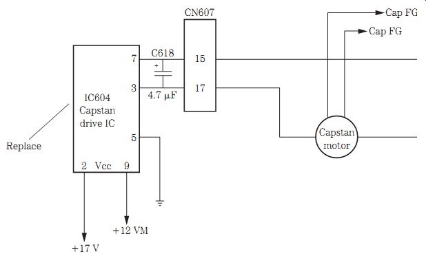
FIG. 14 Replace a defective capstan driver IC for dead or intermittent rotation
in a JVC HRD 170 VCR.
NO CAPSTAN MOTOR, JVC
Sometimes the capstan motor rotation was intermittent and at other times it was dead in a JVC HRD-170 VCR. At first, the capstan motor was suspected of being defective. The motor voltage was monitored at the terminals and was intermittent.
Tracing the motor leads back to motor driver pins 3 and 7, the voltage was still intermittent. Both the 17- and 12-V supply voltages were normal at the capstan motor drive IC604. Replacing the defective IC604 cured the intermittent capstan rotation (Fig. 14).
START/STOP/PLAY, THEN STOPS
Check the capstan driver or control IC when the VCR starts to play and then shuts down. Inspect and clean the mechanism position switch in some models. This problem can be caused by a defective gear drive assembly or bracket assembly. Suspect a defective capstan motor if the VCR shuts down instantly.
A bad capstan motor can shut down the rotation immediately. When the capstan motor stops after a few minutes of operation, replace the motor. Check for badly soldered joints on voltage-dropping or isolation resistors in the power supply when the capstan runs fast and then shuts down.
Check the loading motor IC when the VCR shuts down after a few minutes of rotating and possibly pulls out tape. Suspect a capstan drive IC for intermittent and shut down symptoms. A bad capstan motor driver IC can shut down after 5 seconds with no capstan rotation. The defective capstan motor IC may operate up to 3 hours and then shut down. Suspect a motor voltage regulator IC when in play mode the unit goes to stop and then the capstan motor does not rotate. Check all transistors on the servo PC board when the capstan motor runs in the stop mode. Replace the voltage regulator transistor when the capstan motor begins to play and shuts down.
Fast-forward and rewind problems
Check the 1-A fuse when there are no rewind or fast-forward modes. A bad capstan motor may cause the fuse to blow in play, rewind, and fast forward. The capstan motor may have a flat spot (on the armature) causing no fast forward or rewind. A bad loading motor assembly may produce no rewind, fast-forward, or play modes.
Clean the old grease off the idler gear assembly and re-lube when there is no fast for ward or rewind and the tape occasionally gets stuck.
Replace the forward/reverse bracket and broken shifter when there are no rewind, fast-forward, and play modes. Check for a bad plate assembly for no fast for ward or rewind or slow operation. No play or rewind occurs with a bad slide switch on the carriage assembly. Check for a bad main lever latch on the main cam gear assembly when there is no fast forward, rewind, or play. A bad lever holder assembly and main cam gear can cause no fast forward or rewind. Check for a broken spring on the loading motor assembly when there is no fast forward or rewind, and all other functions are okay. Check for a bad AY assembly when the VCR will not rewind or fast forward.
Check for a bad coil or resistor connection in the voltage source of a motor with no fast-forward or play modes. Suspect a system control IC for no fast-forward, rewind, play, or eject modes. Replace the switching regulator transistor when the VCR will not play, fast forward, or rewind.
A soft brake not engaging or failure to tighten the spring on the soft brake assembly can cause no reverse or fast-forward mode. Clean a dirty cam switch for no rewind, fast-forward, or play modes. Replace the brake solenoid switch for no rewind or fast for ward, whereas other functions might be okay. Damaged teeth in a cam gear can cause no rewind or reverse-search operations. Replace the mode switch when the VCR goes into record, rewind, and fast forward by itself.
FAST FORWARD AND REWIND SHUT OFF
Replace a bad Sycon IC when the VCR powers up, goes into fast forward or rewind, and then shuts off. Besides replacing the Sycon IC, a defective transistor may need replacing on the capstan control when rewind and fast forward shut off in 1 or 2 minutes.
Change both reel sensors when the rewind slows in 7 to 10 seconds and goes to stop. Replace the reel motor assembly when rewind or fast forward stops in 2 to 5 seconds. Check for a bad end sensor on the cassette housing when the VCR stops or goes into rewind or fast forward. Intermittent shutdown caused by an end sensor may let the VCR go to stop and record and then shut down. Replace the take-up reel sensor when the VCR shuts down during play, rewind, or fast forward.
Clean a dirty cam switch when rewind and fast forward are inoperative, and the unit shuts off. The unit may try to load, there is no rewind, and then it shuts off, and this is caused by a bad loading motor cam assembly. Clean the mode switch for slow fast forward and rewind and if the unit plays awhile and then shuts off. A bad mode switch in a Sharp VC2230U VCR caused no eject or fast-forward operation.
Tape ejection problems
Look for defective basket gears when the tape will not eject or the VCR keeps ejecting the tape after loading. A defective lift arm assembly or worn loading belt can keep the tape from ejecting. Check the loading motor and control IC when the tape keeps ejecting. A defective reel motor may not unload the tape. Suspect a right end sensor when the tape loads, the reel rotates, and then the unit ejects the tape.
Suspect a beginning tape sensor when the tape loads and then ejects. Replace the rack front-loading gear assembly when cassette loading is incomplete, and the unit ejects the tape. Replace the gear assembly and side plate when the gears jump, and the cassette will not load or eject. Suspect a bad lift cam when the tape will not eject. A worn wheel unit will not allow ejection of the cassette.
Check the basket gear assembly when there is no ejection operation. A faulty loading or cassette belt can prevent the tape from ejecting. A bad basket gear will not allow ejection of the tape. Suspect a bad basket gear assembly that will not load the tape and may keep ejecting a tape that does load. A bad loading motor and worn cam gear can cause no eject operation. Look for a bad plate assembly, broken teeth, or a faulty loading arm when the tape will not eject.
Intermittent ejection of the tape can be caused by a bad capstan motor. Replace a bad clutch assembly for intermittent ejection. The right-side bracket assembly may cause the front-loading assembly to bind and result in intermittent ejection. Replace the mode switch for no tape ejecting or loading. A bad carriage gear assembly also can cause intermittent tape ejection. A bad connection on the ribbon cable can result in the cassette loading, the capstan motor running, and then intermittent ejection of the tape.
A bad inverter transistor in the power supply can cause slow ejection, a stuck tape, or very little torque on the capstan motor. Check for an open resistor or change in resistance in the switching regulator IC for a unit that does not eject, the tape sticks, or the unit powers up and shuts down in a few seconds. Suspect a loading motor IC or capstan servo circuit IC for no tape ejection. Check for a defective diode in the power source on the main PC board when the cassette will not load or will not eject. A defective loading motor IC (IC215) and servo circuit IC (IC206) resulted in no ejection operation in a GE VG7500 VCR.
A bad bracket assembly can cause no loading or no ejection of the tape. Replace the loading bracket assembly when the tape jams in ejection mode. Suspect a bad capstan motor when the tape loads halfway, the reels will not turn, and then the tape ejects. Look for a defective capstan motor or a cracked pulley when the unit eats tape and will not eject. Replace the loading motor belt when the tape sticks or is intermittent and there is no ejection of the tape. A bad right end sensor may allow the unit to load the tape and the reels to turn, but the unit ejects the tape. Check for a loose ground screw on terminal deck PCB51 when there is no or intermittent ejection in a Zenith VR1820 VCR.
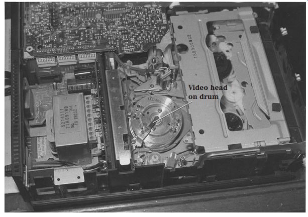
FIG. 15 In playback, the video heads on the drum or cylinder pick up the
recorded signal from the tape and apply it to the playback circuits.
Record and playback problems
The main components within the playback and recording circuits are the video tape heads. In record mode, the video heads apply the signal to the magnetic heads and revolving tape. The magnetic video heads provide video recording and playback as well as audio and control information. In playback, the video heads pick up the recorded signal and amplify it to the playback circuits (Fig. 15).
Check the capstan motor IC when the capstan motor will not turn in play and record modes. Rewind, fast forward, and play do not occur when there is no drum rotation as a result of a faulty control IC. Suspect the voltage regulator IC when there is no fast forward, play, or record. Check the analog-to-digital (A/D) control IC when there is no play, fast forward, or rewind. Replace the capstan motor driver IC when the unit does not play, the take-up reel does not turn, and the capstan motor coils get hot.
Look for an open 1-A fuse when there is no rewind in fast-forward and play modes.
A bad slide switch on the right side of the carriage assembly can cause intermittent functions with no play and record modes. Replace the forward/reverse (F/R) bracket when there is no fast forward, rewind, or play. Check for a bad safety switch when the VCR will not record. Test all leaky electrolytics with an ESR meter on the video PC board for no playback and record in SP mode.
Playback problems
Make sure that the audio/record and erase heads are cleaned before trying to repair the various playback problems. No playback mode can be caused by a broken pin on the limited post lever assembly. No play can be caused by a bad threading motor.
Replace all belts and the mode switch for no video in playback and when the VCR shuts down. A bad diode in the power supply and no UNSW (37 V) can cause no video and tuner playback.
Check for a bad electrolytic (4.7 uF) in the servo IC section when there is no video playback and the tuner is normal. Replace the video/audio process IC when there is no video playback, the screen is black, and the audio is normal. Replace the drum motor IC when there is no playback and the tape goes to full speed and then back to a half speed. No capstan motor rotation in play and record modes was caused by a defective capstan drive IC.
Check the voltage regulator transistor in the power supply for no playback, rewind, or fast forward or the tape gets stuck in the player. No video in the playback mode with normal fast-forward and rewind modes can be caused by low voltage and a defective transistor in the luma-chroma circuits. No playback was caused by a bad 12-V record switch transistor. Replace a leaky record/play switch transistor when there is no video in playback but normal playback audio.
Check the capstan control and driver IC for fast play and intermittent fast forward speed. Intermittent fast speed can be caused by poorly soldered joints on the driver IC. No capstan FG pulse to the system control IC can cause a fast play back speed. Check the bias transistor when there is high-speed playback in EP mode. Clean and insulate the silicon shock absorber conductive plate when there is intermittent speedup of the playback mode. Look for leaky or open electrolytics in the power sources for fast speed in playback. Replace a bad mode switch when the play mode runs too fast and looks like a fast-forward search. A bad capstan stator can make the play mode very jerky.
PLAYBACK SHUTS DOWN
Replace the reset IC when play mode operates by itself and then shuts down.
Play mode will shut down with a defective loading motor IC. Check the wave shaper IC on the tape deck PC board when the play stops in a few seconds in both EP and SP modes and then unloads. A bad diode in the power supply source can cause intermittent capstan rotation and stops in both play and record modes.
Replace the capstan reel driver IC when the VCR shuts down in play mode. Suspect a bad voltage regulator IC when the capstan motor shuts down in play mode.
Replace the capstan motor IC when the VCR shuts down after playing for one half hour.
Replace all belts and the mode switch when there is no video in playback, the tape loads, and the unit shuts down in a few seconds. Check the mode switch when the unit shuts down in play, fast forward, and rewind. Look for a bad reel sensor under the take-up reel when the unit shuts down in play mode. A bad clutch reel assembly can cause the play mode to stop. Check for a bad mechanism position switch if play starts and then stops. A bad drive gear assembly can cause the unit to play and then shut down. A bad bracket assembly can cause the tape to start to play and then shut down. Re-space the take-up reel when play mode shuts down in a few seconds. Suspect a bad photo interrupter when the VCR quits in the play mode.
NO PICTURE IN PLAYBACK
Clean the video heads with chamois and alcohol or a cleaning solvent. Trace the video head wires back to the prerecord amp. Check the universal replacement manual for the right replacement part as well as what stage the IC functions in. If the IC replacement is not listed, trace the signal with a scope. Check the IC number in a similar VCR chassis or schematic.
Check the supply voltage applied to all IC and transistor components within the playback mode. A poor picture in playback can be caused by a faulty prerecord amp IC or luma process IC. Check the voltages on all ICs and transistors to determine if a component is leaky. Inspect the PC board for burned or open resistors.
Snow and noise in the picture or a faint picture can be caused by a defective upper cylinder and head amp IC. Check the tuner-demodulator circuits if there is only half a picture. Resolder the pins on the head amp board and check the VHF block assembly for a fuzzy and noisy picture. Check for a missing control pulse when there is noise in the playback mode. Replacing IC components within the video circuits can solve most playback audio and picture problems.
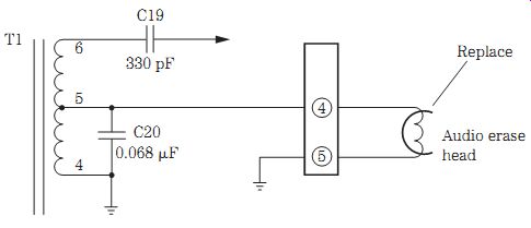
FIG. 16 Replace the erase head when the old recording is not erased in a
Zenith VR1820 VCR.
Poor recordings
Clean the video, audio, and erase heads when there is poor or fuzzy recording. Keep the video heads clean. Does the VCR play back normal audio and video? Usually the same IC circuits are used in both record and playback modes. If the video does not record, suspect additional circuits such as the luma record/playback process IC, transistor record switches, the video record amp, or supply voltages (Fig. 16). Also check the safety switch, record subassembly, and lower drum assembly when there is no video recording.
Replace the erase head if old recordings are present, and the record mode is inoperative. Check for a broken or out-of-line record tab switch when there is no record mode. Suspect a bad safety switch when the unit will not record. Look for a bad recording mode assembly when there is intermittent recording. Leaky capacitors in the video PC board can produce no playback or rewind in SP mode. Replace the lower cylinder assembly when the player shuts down in play or record mode.
Check the voltage regulator IC if the unit shuts down in playback or record mode.
Resolder all voltage regulator IC or transistor terminals for shutdown in record and lost drum synchronization. A bad servo IC can make snowy recordings in SP mode. If the power shuts off after one-half hour in play and record, suspect a defective 12-V IC regulator. Look for a bad transistor in the playback circuits when there is no record or play back. Check all capacitors and ICs when there is no color in record mode.
Suspect a bad control transistor when there is no tape movement in play or record and there are indifferent pauses. Look for a bad silicon diode in the power supply source when there is intermittent capstan rotation or the unit stops in play and record modes.
Replace a bad surface-mounted switching transistor when there is no record mode.
POOR AUDIO RECORDINGS
Check large electrolytics in the power supply circuits when there is no audio in record mode. Test all electrolytics in the bias oscillator circuits with an ESR meter when there is no audio recording. Improper supply voltage in the oscillator circuits can cause no audio recording. A bad zener diode in the 9-V source on the main power supply PC board can result in no audio recording.
Replace small 1- to 5- uF electrolytics on the PB/REC preamp IC for no audio.
Check for a bad PB/REC IC when there is no audio recording. A defective bias oscillator transistor can cause no audio in record mode. Replace a bad oscillator transistor when there is no audio recording, especially when there is old audio still on the tape. No audio record with normal playback can result from a bad bias oscillator transistor. Replace IC5AZ when there is a high-pitched audio squeal in a Mitsubishi HS410UR VCR.
A bad AC head assembly can cause no audio recording. Suspect a bad mode switch when there is no audio or video recording. Open coils on the main PC board can result in no audio recording. Replace the full erase head when there is no audio recording. A defective full erase head can cause intermittent audio recording. A glazed pressure roller can result in no audio recording and may cause a muffled sound. Replace the audio bias transformer for poor audio recording and very poor erasing of the previous recording.
Suspect a bad record safety switch when the audio cuts out during a recording.
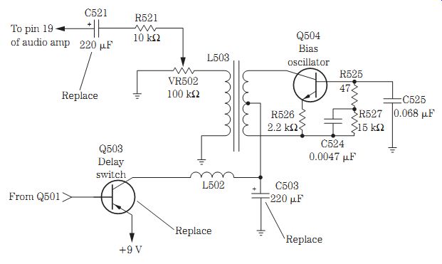
FIG. 17 No erase occurred in an RCA VPT200 VCR with defective C521 (220 uF)
and C503 (220 uF).
NO AUDIO ERASE, RCA VPT200
No audio erase in record or full erase can be repaired with a factory audio parts kit (195685). Also check C521, Q503, and C503 when there is no audio erase in an RCA VPT200 VCR (Fig. 17).
Audio problems
VCR audio bias oscillator circuits are similar to those found in a cassette player. A bias signal is applied to the full erase, audio erase, and audio record/playback heads.
A waveform test at either head will indicate if the bias oscillator is functioning.
Check the voltages on the bias oscillator transistor. Look for a small transistor near the bias transformer. Trace the bias lead from the full erase or audio erase head to locate the small bias transformer. Resolder all transformer board connections when there is intermittent erasing. Check for leaky capacitors across the bias transformer when there is no waveform at the full erase head.
Replace the 12-V regulator IC when there is no driver or capstan rotation and no tuner audio. Check for bad resistors on the IC audio amp when there is no audio in playback. No audio or video can be caused by a defective transistor in the PB 5-V SW circuits. Intermittent audio can result from a defective audio output IC. Suspect a transistor or IC regulator when there is low or no audio supply voltage. Intermittent audio and video can be caused by a defective IC near the video input circuits. Replace the servo IC for garbled audio in EP mode.
Distorted audio in playback can be caused by a 3300- uF electrolytic in the power supply circuits. Suspect a bad electrolytic in the servo phase error line for gar bled audio and erratic operation. Check all electrolytics in the audio playback circuits with an ESR meter when there is no audio reproduction.
A shorted diode in the tuner 30-V line can cause no video or audio from the tuner.
Replace the zener diode in the 9-V record source on the main PC board when there is no audio and normal video. A bad diode in the 6-V line can result in no video or audio.
Replace a bad clutch assembly for an audio wow and flutter symptom. A bad clutch gear can cause garbled audio and slack in the take-up action. When the VCR chews up tape and has garbled audio, suspect a bad take-up clutch bearing that is binding. Garbled audio can be caused by a bad capstan belt. A dirty or worn reel brake band also can cause garbled audio. A broken or loose tension band can result in distorted video and audio. A bad pinch roller bracket can cause the eating of tape and no audio and video. A defective upper cylinder motor bearing can cause garbled sound and a chattering capstan in reverse mode. Clean the audio switching relay when there is garbled audio in EP mode.
Clean the relay contacts for hum in the sound. Check for a broken post and a bad brake take-up reel when there is erratic take-up and quivering audio. Replace a bad brake band when the audio growls. Replace a bad lever assembly on top of the deck for motor boating in the sound.
POOR AUDIO/VIDEO PLAYBACK
Check for a defective IC on the capstan phase error line when there is no audio play back and normal video. A bad servo IC can cause no audio in playback mode. Check the 12-V regulator transistor for no audio and video in the playback mode. Replace a defective transistor on the Sycon PC board when there is no audio or video playback.
No audio in playback can be caused by a regulator transistor in the audio 9-V line on the main PC board. Suspect a bad muting transistor when there is no audio in play back mode. Check the surface-mounted transistor playback switch on the video head assembly when there is no video or audio in playback.
Suspect electrolytic capacitors in the servo circuits when audio playback is gar bled and erratic. Check all electrolytics on the head amp section when there is no video or audio in rewind or playback. Open capacitors in the audio section on the main PC board can cause no audio in playback with normal video. No audio or video in playback can be caused by a shorted electrolytic on the video head picture amp board. A bad electrolytic (330 uF) on the UNSW 5-V line can cause distorted video in playback. A shorted electrolytic on the audio/video board can cause no erase of the old audio.
A bad pinch roller bracket can result in no audio or video in playback. No audio in playback with a noisy right channel can be caused by a defective audio/CTL head assembly. Open coils in the head circuits will not play back the audio. A bad clutch assembly can cause a flutter in audio playback and record.
No audio erase can be caused by no voltage supply to the bias circuits with open resistors. Suspect a bad bias oscillator transistor when there is no erase of audio in record mode. A defective full erase head can cause low or no audio. A bad AC head or full erase head can cause a very low or no audio playback. Check the wiring on the heads for intermittent playback audio. Check for poorly soldered connections on the full erase head when the unit will not erase the old audio from a previous recording. No audio or full erase can be caused by a defective IC on the +9-V record bias circuit. Replace the audio bias transformer for poor audio recording and a very poor erase problem.
NO ERASE OF OLD AUDIO, RCA VR250
The bias oscillator tested normal in the erase head circuits of an RCA VR250 VCR.
The voltage supplied to the bias oscillator was normal. Q501 and Q503 in the center tapped circuit of the bias oscillator were checked with the diode tester of a digital multimeter (DMM). Q501 was open. Replacing Q501 with an ECG125 universal transistor solved the no-erase problem (Fig. 18).
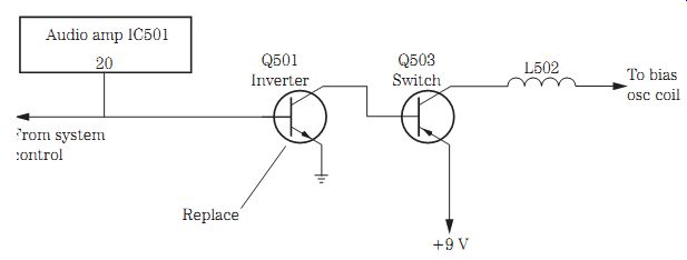
FIG. 18 Q501 caused no erase of the old audio in an RCA VR250 VCR.
Lines and noise
Very loose back tension can produce flagging at the top of the picture. A bad tension band can cause snow to come and go in the picture. Check all electrolytics for hum bars in the picture. Poorly soldered bad head amp connections can cause a snowy video in EP and SP modes and looks like a bad tape head. Poor adjustment of the cylinder can cause noise bars drifting through the picture. A bad upper cylinder can cause noisy lines in the picture in playback. A bad upper cylinder also can cause white lines in tape recording.
Check the system control IC when there is no video in playback or the picture jumps and flutters. A bad electrolytic on the system control IC can cause bad tracking, chipmunk speed, and lines of snow. A bad servo IC can cause lines through the video and looks like a bad drum motor. A bad servo IC can cause the upper cylinder to rotate more slowly than normal and produce lines in the picture (Fig. 19). A defective servo IC can produce a snow bank moving in the picture with audio wow and flutter.
Replace the capstan control IC for noise bars in review mode. Check for a defective transistor on the preamp PC board when there are hash marks, no audio in record, and normal audio recording.
When the unit will not load all the way or there are lines in the top of the picture, lubricate the loading ring assembly, and tighten the back spring slightly. Check for a loose head relay switch when there are noise lines in record and play mode. Realign and service tape guides for lines in the video during playback. Lines in half the picture can result from a dirty or stuck switching relay.
Replace bad filter capacitors in the power supply for lines in the picture, bad color, and the appearance of a bad tape head. Bars through the lower part of the picture can be caused by a defective 1- uF electrolytic on the drum pulse generator line in the servo section of the PC board. Open electrolytics on the drum or cylinder drive PC board can cause horizontal lines in the picture at all speeds. Replace the 3.3- uF surface-mounted capacitor on the lower cylinder for lines in playback and the appearance of a bad tape head.
Noisy conditions
Replace the mode switch when the unit makes a grinding noise with no picture in reverse, pulls out tape when ejecting, and may have intermittent operation. A bad worm gear in the loading assembly can cause a clicking sound. A bad trigger gear assembly can cause a mechanical grinding noise. A loose tape guide post can cause a tracking noise. A high-pitched squeal on play and record can be caused by a bad static discharge arm on the upper cylinder assembly. Noise in the picture can be caused by a bad upper cylinder. Replace the left loading link lever when there is a noisy band at the top of the picture. Replace bad drum stators when there is noise in the picture. A bad clutch wheel can result in a loud grinding noise.
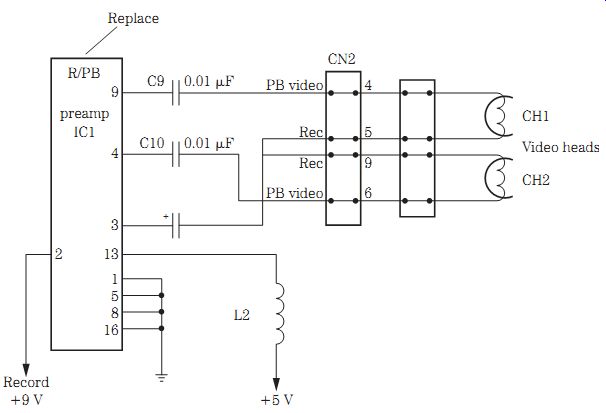
FIG. 19 A bad PB/REC preamp IC caused the upper cylinder or drum to rotate
slow and produced lines in the picture of a JVC HR-D1700 VCR.
Check all electrolytics on the power supply board when there is a squeal in the power supply. A bad power transformer on the switching block can cause a low-level whine or squeal. A bad electrolytic in the regulator circuits can cause noise in the picture when the capstan motor stops. A shorted diode in the 30-V line can cause a hissing noise.
When the loading belt screeches, check the rack and bracket assembly. A bad switching audio relay can cause noise in the audio. A bad relay also can cause a cracking and static noise in the audio playback mode. Check the carriage arm on the side of the cassette loading mechanism for a grinding noise. Replace the bushings in the capstan motor bearing holder for a vibrating noise in fast forward or rewind or during mode changes.
Dew circuit operations
Resolder the pin terminals on the servo control IC when there is no dew light. Check for a foil or trace break on the servo control IC terminals if there is no dew light. Re place the sensor lamp when there is no dew light, the tape loads, and there are no functions. Resolder the transistors or ICs for no operation of the dew light. Check for open connections on the servo IC when there are functions and the dew light is flashing. Check all traces and PC wiring breaks with an ESR meter. Replace a bad dew light sensor when the flashing stop light is on. Suspect a bad transistor in the dew light circuits when the dew light flashes.
Table 1. VCR service schedule (Radio Shack).
Service schedule of components
Clean all parts involved in tape transport (upper drum and video head/pinch roller/audio control head/full erase head) using 90 percent isopropyl alcohol. Check Table 1 for the suggested maintenance for VCR components. A listing of VCR numbers keyed to VCR manufacturers is shown in Table 2.
TV/VCR combo repairs
Most of the mechanical problems found in a regular VCR can exist in a TV/VCR combo.
Troubles found in any TV chassis also can be found in the TV/VCR combo. You may find an AM/FM radio in the same TV/VCR chassis. The big difference in the TV/VCR combo is the power supplies. You may find two different types of power supplies, one in the TV and another in the VCR circuits. In a Panasonic PV-M2021 TV/VCR, a switching power supply powers the VCR circuits, whereas a line voltage regulator power supply supplies voltages to the TV circuits. Only one power supply may power both the VCR and TV in some models. Two different power supplies are found in the early battery-powered and power-line portable TV/VCRs. The same test equipment can be used to service a TV/VCR combo as found on any service bench (Fig. 20).
Table 2. UL listing number to VCR manufacturer (unofficial)
TV/VCR part layout
Usually the VCR is located at the front of the chassis within a shielded container. The VCR chassis can be removed by taking out several screws that hold moving and loading components. A shielded bottom piece can be removed to get at the TV PC board.
Follow the removal procedures found with any TV/VCR combo service literature if the exact service information is not available. Most of TV parts can be seen on the side and toward the rear of the TV chassis. For those who service TVs as a warranty station for certain brands, several different manufacturer cables and plug-in connections can be obtained for easy servicing.
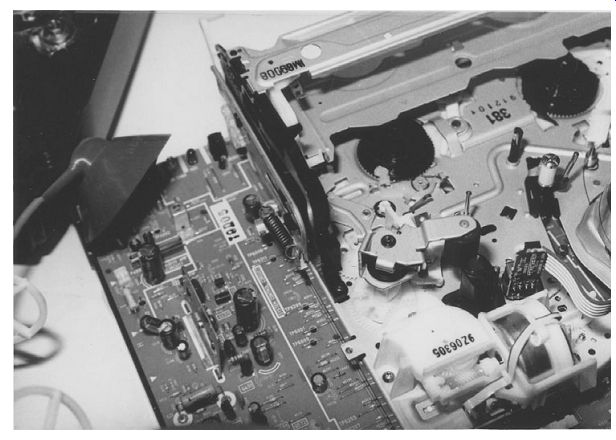
FIG. 20 The TV circuits are located around the side and rear with the VCR
in the front in a Panasonic TV/VCR.
The power supply
A standard raw dc power line supply may contain a bridge rectifier circuit with small-ohm resistors and a large electrolytic capacitor filter network. The switching low-voltage power supply is the same as the switching supply in a regular TV circuit.
You may find a raw dc power supply and a switching power supply in one TV/VCR chassis. A Panasonic PV-M1347 TV/VCR contains a switching power supply in the low-voltage circuits and secondary voltages from the flyback for both the TV and VCR circuits. A switch-mode power supply (SMPS) is found in an RCA 13TV701/19TVR60 unit. All ac power supplies should be serviced with the TV/VCR plugged into an isolation transformer.
In the early 9- and 13-in TV/VCR combos that operate from batteries and a switching power supply, a separate switching control IC, transformer, and silicon diodes provide a +117-V dc operating voltage. The power line switching power sup ply provides +117- and +33-V sources for the TV circuits. The battery power supply may furnish a +117-V source to the cathode-ray tube (CRT) and high-voltage (HV) circuits, with 6 and 12 V to both the TV and the VCR. Silicon diodes are placed in the voltage sources so that when in ac operation the voltage does not feed back into the battery circuits (Fig. 21).
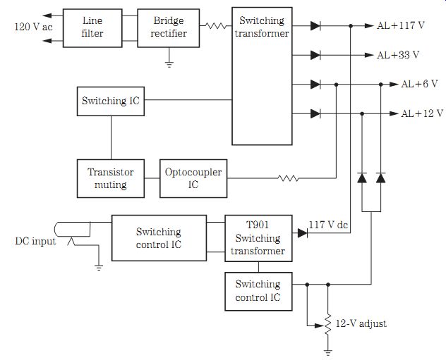
FIG. 21 Block diagram of a battery-operated and ac switching power supply
in a portable TV/VCR.
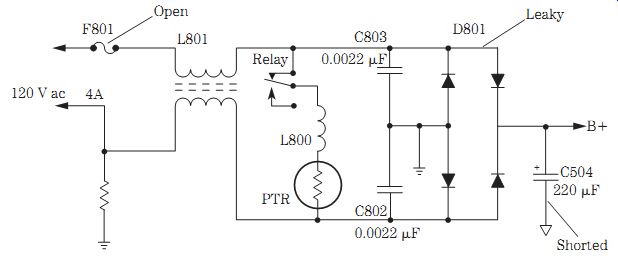
FIG. 22 A shorted C504 (220 uF, 250 V) damaged D801 and F801, resulting in
a dead chassis in a Daewoo DVQ-19H2FC TV/VCR.
Separate 5-, 6-, and 9-V regulator transistors are found in the output voltage circuits. The 5-V regulator is fed from the +6-V source, and the -6-V source is fed from the +12-V line with a voltage regulator transistor. The +117-V source feeds the CRT and HV circuits. The +33-V source provides power to the tuner and servo system control circuits. The tuner, system control, and TV micon circuits are supplied by the +5-V source. The +6-V source feeds the VCR servo system control circuits. The +12-V source provides voltage to the audio output and capstan control circuits. The tuner, video, and chroma circuits are powered by the +9-V source.
Extra care must be exercised when servicing the switching power supplies to take critical voltage measurements within the hot and cold systems so as not to damage other components and also to obtain the correct voltage reading. Critical voltage measurements without a schematic can be compared with those of another TV/VCR chassis. A slip of the test probe, however, can damage other parts in various TV/VCR circuits.
The raw dc power circuits
The raw dc power supply is like that found in a regular power line voltage source.
The most common problems in the power line supply are a blown fuse, burned low ohm resistors, shorted or leaky silicon diodes, open or leaky transistor or IC voltage regulators, and leaky or open filter capacitors (220 to 680 uF, 250 V). You may find a defective relay that turns on the TV or the degaussing circuits. Often a leaky or shorted silicon diode blows the main fuse. A shorted electrolytic filter can blow the main fuse or lose capacity, which can shut down or prevent startup of the TV chassis. A bad ac relay may cause intermittent startup or prevent startup of the chassis.
Service the power line circuits with extreme care (Fig. 22).
Relay problems
A relay may turn the TV on or off or operate in the degaussing circuits. Check the relay for an open solenoid, bad solenoid connections, bad relay driver transistor, or poor ac connections. When a relay does not click and there is a dead chassis, check for an open relay coil, a bad electrolytic in the relay circuit, or a damaged relay caused by lightning or a power line surge. A defective relay with stuck points, a defective relay driver transistor, or a shorted diode across the solenoid can produce a no shutoff symptom. Check the relay for bad switching points, a defective relay transistor, or badly soldered joints on the ac side of the solenoid.
When a relay chatters, check for a defective electrolytic in the relay voltage source, a faulty main filter capacitor, and poorly soldered terminals on the small resistors in the relay circuits (Fig. 23). The relay would not close in a Magnavox CRN200AT01 TV/VCR, and this was caused by a faulty diode (D008).
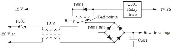
FIG. 23 Bad relay points in an Emerson VT1920 TV/VCR caused an intermittent
power-up symptom.
Switching transistor circuits
Notice that the input circuits from the raw dc power supply have a hot ground. The secondary side of the switching transformer has a cold common ground. Take the hot ground measurements from the main filter capacitor ground for accurate input readings.
Most service problems found in switching power supply circuits are a leaky or shorted switching transistor, a bad switching IC, a blown line fuse, a defective IC regulator, a leaky voltage transistor regulator, and faulty silicon diodes. Service the switching transistor like you would the horizontal output transistor in the horizontal output circuits.
In a Panasonic PV-M2021 TV/VCR, the switching power supply receives the raw dc voltage from a bridge rectifier (D1001) and a main filter capacitor C1004 (120 uF, 200 V). The switching transistor (Q1001) and switching control transistor (Q1002) operate in a hot ground primary winding of the switching transformer (T1001). Five different voltage sources are found in the secondary side of the switching transformer. The secondary voltage sources have a common ground (Fig. 24).
Filter capacitor problems
Defective filter capacitors can cause dead, intermittent, poor power-up, and chassis shutdown problems. A dried-up filter capacitor can cause a low output voltage source, a shrunken picture on both sides, severe weaving of the picture, hum bars in the raster and hum in the speaker, an hourglass pattern, very light horizontal bars moving up the screen, and intermittent shutdown symptoms. Check for accurate dc voltage across the main filter capacitor. A shorted or leaky filter electrolytic can be checked on the low-ohm scale of a DMM. Quickly check the condition of the filter capacitor on an ESR meter.
Before taking ohmmeter and ESR meter tests, discharge the electrolytic filter capacitor so as not to damage the meter. Clip another electrolytic across the suspected one with the power turned off so as not to damage other semiconductor components. Notice if the hum or black lines are gone when the chassis is started up. Make sure that the test electrolytic has the same or higher voltage and capacity as the suspected capacitor.
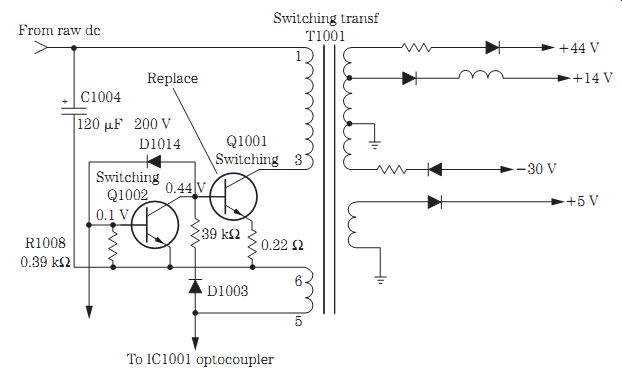
FIG. 24 Switching transistor Q1001 became shorted and blew the main fuse
F1001 (0.6 A) in a Panasonic PV-M2021 TV/VCR.
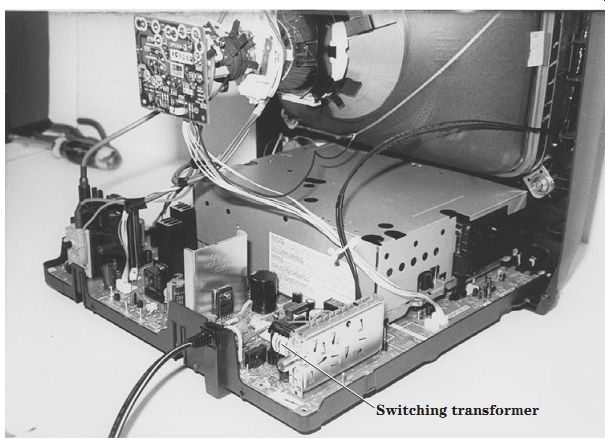
FIG. 25 The switching transformer is found on the rear chassis of a Panasonic
13-in TV/VCR.
Switch-mode power supply
The switch-mode power supply (SMPS) receives a raw dc voltage from the bridge rectifier power supply input circuits. A power line dc voltage is fed directly to the switching transformer with an output transistor and an IC regulator in the primary circuits. The feedback transistor is in the lower primary winding with an isolator coupler separating the input and output circuits. All the hot grounds are found in the primary side of the switching transformer. The common grounds are found in the secondary circuits (Fig. 25).
Most switch-mode power supplies can be serviced as the switching power supply.
A quick voltage test across the main filter capacitor indicates if raw voltage is applied from the bridge rectifier circuits. Check the various voltage sources after the sil icon diodes or across filter capacitors in the secondary circuits of the switching trans former. Dried-up electrolytics can lower the dc voltage sources.
Test the isolator IC with the diode tester of a DMM. The primary or hot side of the IC can check the light-emitting diode (LED) inside the isolator on terminals 1 and 2.
Replace the isolator IC if a low ohm measurement is found on the transistor side. Check the transistor side with the diode tester of a DMM. A low resistance measurement with reversed test leads indicates a leakage between the collector and emitter terminals (3 and 4). A GE 13TVRU1 TV/VCR squealed when plugged into the power line and would not turn on due to a defective C810 (470 uF, 16 V) electrolytic in the power supply.
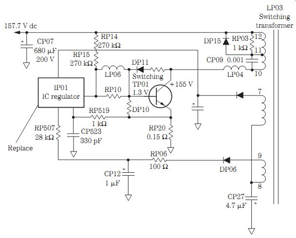
FIG. 26 Replace the IC regulator (IP01) in an RCA 13TVR60 TV/VCR with a dead
symptom.
Dead chassis
A high dc voltage was found on the collector terminal of the switching transistor in an RCA TV/VCR chassis. TP01 tested normal with the in-circuit diode tester of a DMM. The emitter resistor RP20 (0.15 ohm) was fairly normal. All diodes within the primary winding of the switching transformer tested good. Voltage measurements on the IC regulator (IP01) were way off. The regulator IC (IP01) operates in the hot ground side of the switching transformer (LP03). Replacing the bad regulator IC (IP01) solved the dead chassis symptom (Fig. 26).
FIG. 27 Replace a defective line voltage regulator (IC801) in a Panasonic
PV-M2021 TV/VCR with a dead chassis and clicking of the relay.
Power line regulators
Besides a switching power supply, power line regulator circuits are found in a Panasonic PV-M2021 TV/VCR. The raw dc voltage feeds _132 V to power line regulator IC801. A defective power line regulator can cause no startup and shutdown problems. The defective power line regulator also can cause the TV to shut down when the power line voltage is over 100 V ac. Suspect the power line regulator when the TV becomes intermittent. A narrow picture may result from a defective line voltage regulator (Fig. 27).
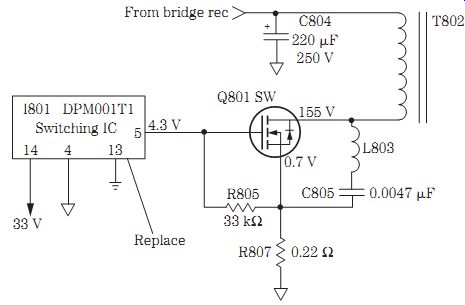
FIG. 28 Replace the switching IC (I801) in a Daewoo DUN2056N TV/VCR when
the chassis is dead, it tries to start up, and a pulsating noise is heard
in the speaker.
No startup and shutdown
The startup and shutdown problems in a TV/VCR combo are the same as in a regular TV chassis. No startup in a TV/VCR was caused by a defective 33- uF electrolytic that lowered the dc voltage to 15 V from a 112-V source. Large electrolytics and diodes also can cause intermittent startup and shutdown symptoms. A dead TV/VCR might try to start up, and this may be caused by a defective line voltage regulator IC in the power supply circuits. A 470- uF electrolytic can cause intermittent startup and a ticking sound. A defective switching IC in the power supply can cause a dead chassis that tries to start up and has a pulsating noise in the speaker (Fig. 28). Intermittent startup with the power light on in a Samsung VT1921 TV/VCR was caused by a badly soldered joint on the 12-V secondary IC regulator in the power supply.
When a TV/VCR chassis shuts down, the results are the same as those found in a regular TV chassis. When the high voltage comes up and then shuts down immediately in a Symphonic TVCR13E1, this is caused by a bad 6-V regulator on the power supply board. In a Symphonic TVCR13F1 TV/VCR, the TV was dead, and when the voltage was raised to +112 V, the set came on and then shut off; this was caused by a bad 6-V regulator. A Zenith SMV-1315 TV/VCR came on momentarily with high voltage and then shut off; this was caused by defective IC1003, IC1004, and IC1502. A Zenith SMV-19415 TV/VCR cycled on and off when plugged in, and this resulted from a badly soldered joint on the horizontal output transistor (Q9002).
Defective IC602 and IC603 in a Magnavox CCT13AT02 TV/VCR caused the TV to come on with high voltage and then shut off. The chassis in a Sylvania SSCO90 TV/VCR would shut down as a result of a defective IC602. A Symphonic SC3919 TV/VCR came on and then shut off immediately and would come on again for 35 minutes or so, and this was caused by a defective 6.8-V zener diode (D224) off of pin 2 of IC201.
EEPROM troubles
The TV/VCR chassis has the same EEPROM problems as a normal TV chassis. A TV/VCR with no vertical or horizontal sync, no color or audio, and no vertical or horizontal sync when a tape was played was the result of a defective EEPROM. No tuner action and raster with normal on-screen display was the result of a bad EEPROM IC. Many scanning lines with no tuner action was found in a TV/VCR to be the result of a defective EEP ROM. A defective EEPROM (IC202) in a Sharp 27VSG300 TV/VCR caused a white raster with retrace lines, no tuner action, and no audio. When playing a tape in the same TV/VCR, there was no video with normal audio, and this also was caused by a defective EEPROM. Again, in the same Sharp TV/VCR chassis, there was no tuner action except an on-screen display, and when a tape was played, there was video and normal audio.
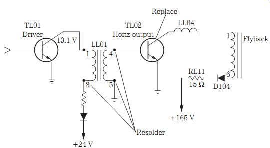
FIG. 29 Resoldering connections on the horizontal driver transformer and
replacing the horizontal output transistor (TL02) revived a dead chassis
in an RCA 13TVR60 TV/VCR.
Horizontal sweep problems
Horizontal sweep problems in TV/VCR chassis are the same as those in a regular TV chassis. A dead Daewoo DVN20FGN TV/VCR tried to start up and had a pulsating noise in the speaker caused by a faulty T803. After turn-on, a Funai F3809K TV/VCR worked okay for 15 to 20 minutes and then the raster became bright with retrace lines; this was caused by a defective flyback. The TV was dead but the VCR worked okay with an open F802 fuse in an MGN NVR9500 TV/VCR, and this was caused by a shorted horizontal output transistor (Q402) with a badly soldered joint on the horizontal driver transformer.
A bad flyback in a Symphonic SC319A TV/VCR produced a dark raster and poor focus when the screen control was turned up. The bad horizontal output transistor (Q402) in a White-West WTV-11911 TV/VCR caused a dead symptom with a normal fuse symptom. A Funai F19TRB1C TV/VCR was dead; when it was plugged in, a squealing noise was heard, and this was caused by a bad horizontal output transistor. In a Zenith SRV-1300S TV/VCR, the TV was dead but a noise heard inside the set, and this was caused by a defective horizontal driver transformer (T571) with an okay fuse symptom (Fig. 29).
A NARROW PICTURE
A narrow picture or a picture with both sides pulled inward can be caused by defective components within the power supply or horizontal circuits. A defective power line voltage regulator IC can produce a narrow picture. Poor connections on the horizontal driver transformer can cause an intermittent raster with the sides pulled in.
Be aware of the narrow picture problems found in the power supply and horizontal circuits of a regular TV chassis and compare them with those in the TV/VCR chassis.
In a Panasonic CT-13R20K TV/VCR, the fuse was okay, and the narrow picture was caused by a defective IC801 (STR30130) power line regulator. Replace IC3001 in a Panasonic PV-M2021A TV/VCR that has a loss of video after the set is on for 15 minutes, and when it is turned on again, the picture is pulled to the right. This is caused by a faulty C553 capacitor (0.002 uF). Check C12 (4.7 uF, 250 V) and C231 (100 uF, 160 V) in a Zenith SLV-1940S TV/VCR when the picture shrinks on both sides and then the raster fades out after the TV is on for 2 to 5 minutes. Reduced width in a Memorex 16 411 TV/VCR was caused by a badly soldered joint on Q1008.
Vertical problems
The vertical problems found in the TV/VCR chassis are about the same as those in a regular TV chassis. No vertical sweep in an Emerson TV0952 TV/VCR was caused by a defective resistor (R467). Intermittent loss of vertical sweep was found in an Emerson VT3110 TV/VCR and resulted from badly soldered joints on IC402. Loss of vertical sync and flag waving at the top of the picture in a Magnavox CRN200AT01 TV/VCR were caused by a bad IC1 module. No raster was noted and, when the screen control was turned up, there was no vertical sweep in an RCA T25003BC TV/VCR, and this was caused by faulty IC501, R511 (3.9 ohm), and C508 (100 uF, 35 V). In another chassis with the same model number, loss of vertical sweep after operation for 5 minutes was caused by a badly soldered joint on IC501.
After replacing the IC602 (K1A7806) regulator for a dead chassis, a Symphonic TVCR9E1 TV/VCR had no vertical sweep, and this was caused by a defective vertical output IC (LA7837). No vertical sweep in a Zenith TVSA1320 TV/VCR resulted from a bad IC541 (LA7837) (Fig. 30). Loss of 1 in of vertical sweep at turn-on in a Funai SLV 19405 TV/VCR after warmup was caused by a faulty C01 electrolytic (100 uF, 16 V).
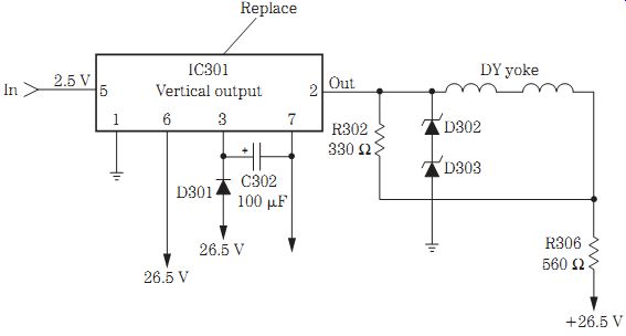
FIG. 30 A normal vertical drive waveform was found on pin 5 of the vertical
output IC301 with no vertical sweep and was caused by a bad output IC in
a Daewoo CN-071 chassis.
VERTICAL RETRACE LINES
Check the vertical sweep circuits for vertical retrace lines in a TV/VCR, the same as in a regular TV chassis. A white raster with retrace lines was cause by a bad EEPROM in a Sharp 27VSG300 TV/VCR chassis. A Funai F3809A TV/VCR worked okay for 15 to 30 minutes, and then the raster became bright with retrace lines; this resulted from poorly soldered connections around the vertical output IC. Replace IC401 (LA7837) when two white lines appear in the bottom 2 in of the screen with horizontal tearing in a JVC TV-C2026 TV/VCR. At turn-on there was a bright screen and retrace lines and then no vertical sweep in a Symphonic TVCR13D1 TV/VCR, and this was caused by faulty C9012 (1 uF, 250 V) located near the flyback.
Poor or no video conditions
The same video problems found in today's TVs are the same as those found in TV/VCR chassis. After replacing C07 (220 uF, 6.3 V) in a Funai G19TRB1C TV/VCR for a dead symptom, the raster appeared extremely bright and could not be turned down. This resulted from defective electrolytics C09 (4.7 uF, 160 V) and C12 (4.7 uF, 250 V). A washed out and smeared picture in a Funai FC1300T TV/VCR was caused by a leaky electrolytic C9003 (4.7 uF, 250 V). Wavy black lines with dark shading in the picture on both the TV and the VCR resulted from two defective 330- uF, 6.3-V electrolytics.
A bad EEPROM produced a white raster with retrace lines in a Sharp 27VSG300 TV/VCR. Excessive brightness in a Panasonic PV-M2021 TV/VCR was caused by a defective IC1 located near the VCR board. Defective IC02 in a Zenith SLV-1940S TV/VCR resulted in no video from either the tuner or the VCR but a normal raster and audio.
Replace IC1 in a Quasar UV1220A TV/VCR that shows no video and a bright raster in VCR operation.
TV/VCR color problems
The color problems found in both TV/VCR chassis and regular TV chassis are the same, except a few symptoms may be different in the TV/VCR. A defective IC201 provided a blue screen with no audio and retrace lines in a Sharp 13VTF40M TV/VCR.
Intermittent color was found in a Panasonic PV-M2021 TV/VCR with a bad color IC.
The luminance and chrominance main signal processor was contained in IC301. The supply voltage on pin 16 was very low and should have been around 12 V. No color waveform was normal off the color crystal on pin 19. No correct waveforms were found off pin terminals 9, 10, and 11 with very low voltage. Suspected IC301 was replaced, and this solved the intermittent and no color symptom (Fig. 31).
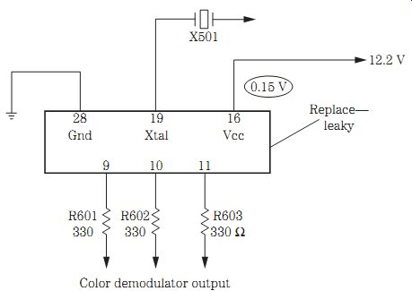
FIG. 31 Intermittence and no color were found in the luminance and chrominance
IC301 in a Panasonic PV-M2021 TV/VCR.
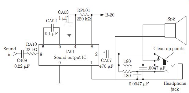
FIG. 32 Dirty headphone plug points in an RCA 13TV70 TV/VCR caused intermittent
audio reception.
TV/VCR audio problems
Most small-screen TV/VCR combos employ a single audio output IC. Most audio problems are the same in a TV/VCR chassis as in a regular TV chassis, except those found in the VCR section. Check for a badly soldered joint on IC502 in an Emerson VT1321 TV/VCR that has no audio or raster. Replace IC801 (STR3220) and R805 (10 kilohms) when there is a white raster and no audio in a Panasonic ADP208 TV/VCR chassis. No audio in a Protec TVCR13131 TV/VCR was caused by a faulty IC01 (AN5265). The surface-mounted IC3001 in a Panasonic PV-M2048 caused a no audio symptom.
Suspect C4202 (220 uF) on the tuner board when there is no audio in a Funai F13TRB1 TV/VCR. Hum in the speaker, plus hum bars moving up the screen, resulted from a defective electrolytic C455 (2.2 uF, 315 V) on the TV board and C1102 (3300 uF, 35 V) on the VCR board in a Samsung VM7003 TV/VCR. Badly soldered joints on C801 (330 uF, 16 V) and C803 (10 uF, 16 V) caused no audio from the TV when a tape was played in a Symphonic TVCR13F1 TV/VCR (Fig. 32).
A bad speaker in a Panasonic PV-M2559 TV/VCR indicated a distorted-audio symptom. A defective head phone jack with dirty contacts in a Symphonic TVCR961 caused a no-audio symptom in the TV or VCR mode. A cracked board where the earphone jack was connected produced intermittent audio in a Zenith SMV-19415A TV/VCR.
============