AMAZON multi-meters discounts AMAZON oscilloscope discounts
Tubes (vacuum-tubes) are distinctly old-fashioned in these days of transistors and other semiconductor devices, yet they are still widely used in commercial circuits, especially where high power levels are involved.
The basic form of a tube is an evacuated glass envelope containing two electrodes--a cathode and anode. The cathode is heated, causing electrons to be emitted which are attracted by the anode, thus causing current to flow through the tube in the basic circuit shown in Fig. 12-1 (first diagram).
The original form of heating was by a separate low-voltage supply to a wire filament forming the cathode. The later form is a cathode in the form of a tube with a separate heater element passing through it. This is known as an indirectly heated cathode, particular advantages being that there is no voltage drop across the cathode (and thus electron emission is more uniform), and also the heating filament can be connected to a separate ac supply, if necessary, rather than requiring a separate dc supply. Otherwise, the working of the tube is identical. Both require a filament supply and a separate high voltage supply.
DIODES
The simplest form of tube shown in Fig. 12-1 is called a diode, because it has two internal elements. Its working characteristics are that when the cathode is heated, application of voltage across the anode and cathode will cause a current to flow, the current value increasing with anode voltage up to the saturation point, Fig. 12-2.
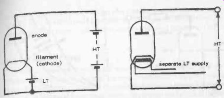
Fig. 12-1. Diode vacuum tubes with directly heated filament (left); and indirectly
heated filament (right).
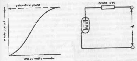
Fig. 12-2. Typical diode characteristics (left). To do useful work, the anode
current must flow through a load resistor.
Current can only flow in one direction (i.e., positive connected to anode, when current will flow from anode to cathode in the opposite direction to electron flow (see Section 2). If the direction of HT is reversed, then the value will not conduct. In other words, a diode works as a rectifier in this case.
Note that in this "working" circuit a load resistor is included in the circuit. Without any external load in circuit, all the power input to a tube would be used up in heating the anode.
To do useful work, a tube must work with a load of some kind or another, so that power is developed in the load.
To work efficiently, most of the input power must do useful work in the load, rather than in heating the anode.
Thus the voltage drop across the load should be much higher than the voltage drop across the valve.
TRIODES AND TETRODES
If a third element, known as a grid, is inserted between the cathode and anode, a negative bias voltage can be applied to this to control the working of the tube and thus the anode current. Such a tube is known as a triode, a basic circuit for which is shown in Fig. 12-3, together with characteristic performance curves. The advantage of this mode of working is that a small change in bias voltage (or voltage applied to the grid) is just as effective as a large change in anode voltage in bringing about a change in anode current.
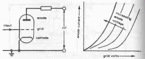
Fig. 12-3. A triode is a three-element tube. Anode current is controlled
by the grid "bias" voltage.
The triode is a particularly versatile type of tube which can readily be made to work as an amplifier, or an oscillator (an oscillator is really only an amplifier working with excessive feedback producing self -sustained oscillation). It does, however, have certain limitations which may be disadvantageous in certain circuits. One is that the inherent capacitance generated between the anode and grid can materially affect the performance of an amplifier circuit where the presence of this capacitance is aggravated by what is called "Miller effect." To overcome this particular limitation, a positively biased second grid, called a screen grid can be inserted between the grid and anode. In effect this acts as an electrostatic shield to prevent capacitive coupling between the grid and anode. Such a four -element tube is known as a tetrode, see Fig. 12-4A.
Even the tetrode is not without its faults. The cure for one limitation (interelectrode capacitance) has produced another fault. The screen grid tends to attract secondary emission electrons bouncing off the anode because it has a positive bias, whereas in the triode the only grid present is negatively biased and tends to repel secondary-emission electrons straight back to the anode.
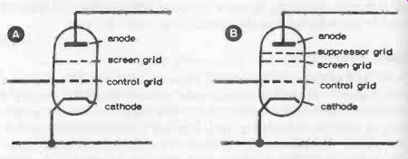
Fig. 12-4. Tetrode (left) and pentode (right) tubes, shown in simple diagrammatic
form.
PENTODES
To overcome this effect in a tetrode, a fifth element is added, called a suppressor grid, inserted between the screen grid and the anode (Fig. 12-4B). This acts as a shield to prevent secondary emission electrons being attracted by the screen grid.
A five-element valve of this type is called a pentode.
THE CATHODE-RAY TUBE
The cathode-ray tube has the same number of elements as a triode (heated cathode, anode, and grid) but works in an entirely different manner.
Instead of electrons emitted by the cathode flowing to the anode, they are ejected in the form of a narrow stream to impinge on the far end of the tube, which is coated with a luminescent material or phosphor, so producing a point of light.
This point of light can be stationary or moving, its direction after emission from the far end of the tube being influenced by the magnetic field created by two additional sets of electrodes or plates, positioned at right angles, Fig. 12-5. This plates are designated X and Y. Voltage applied to the X plate displaces the light spot in a horizontal direction; voltage applied to the Y plates displace the light spot in a vertical direction. See Section 23 for a more detailed description of the working of a cathode-ray tube.)
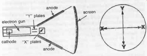
Fig. 12-5. Simplified diagram of a cathode-ray tube.
A cathode-ray tube can be used as a voltmeter, with the advantage that it puts no load on the circuit being measured.
Cathode and anode are connected to a separate supply, the voltage to be measured being connected to the Y plates. A dc voltage will displace the spot a proportional distance above (or below) the center line of the tube. If the voltage applied is ac, the light spot will travel up and down at the frequency of the supply, which will usually be too fast for the spot to be identified as such, so it will show a trace of light in the form of a vertical line, Fig. 12-6. The length of this line is proportional to the peak -to -peak voltage of the ac.
The more usual application of the cathode-ray tube is in an oscilloscope, where a voltage which is increasing at a steady rate is applied to the X plates. If another varying voltage is then applied to the Y plates, the spot will "draw" a time graph of this voltage, or a picture of the waveform of that voltage. The X plate varying voltage supply is usually arranged so that once the spot has swept the width of the screen it returns to the start and repeats the picture over and over again.
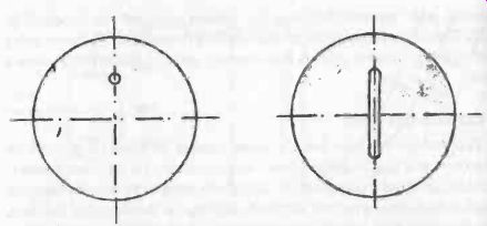
Fig. 12-6. Simple display of do voltage (left) and ac voltage (right) on a
cathode ray tube. The vertical displacement is a measure of the value of the
voltage concerned.
The rate of repetition is determined by the time base of the X plate circuit, this being one of the most important features in oscilloscope design in order to achieve a steady trace at the required frequency. Separate "shift" controls are also usually provided for both X and Y deflection so that the starting point of the light spot can be set at any point on the screen.
Amplifier circuits are also essential in order to be able to adjust the strength input signals applied to the Y plates, and also the X plates if these are also to be fed with an input signal instead of the time base. With these refinements (and others) the cathode-ray oscilloscope is one of the most useful tools an electronics engineer can have.