AMAZON multi-meters discounts AMAZON oscilloscope discounts
One of the big problems facing most beginners is actually how to construct a working circuit, i.e., turn a theoretical circuit diagram into a connected -up assembly of components (with all the connections correct, of course!).
The following diagrams show six very simple and straight -forward methods of tackling elementary circuit construction - all capable of giving good results with the minimum of trouble, and especially recommended for absolute beginners at practical electronics.
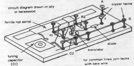
Fig. 20-1. Pinboard construction starts by drawing a working plan of the circuit
on a panel of ply or balsa. Then drive in copper tacks at each connection point.
Solder component leads to tacks, and complete circuit as necessary with any additional wiring.
PINBOARD CONSTRUCTION
Draw out the component layout for the circuit on a piece of thin ply (or even hard balsa sheet), using a ballpoint pen (not a lead pencil). Draw in all connections and mark points where common connections occur with a blob (just as on circuit diagrams).
Cut out the panel to a suitable size. Drive copper tacks into each b and simply solder the components in position. Complete additional connections with plain wire, see Fig. 20-1.
SKELETON ASSEMBLY
Start again with a component drawing, this time on paper. Lay components in place, bending the leads of resistors and capacitors to complete connections. Other connections can be complete with two lengths of 16 gauge copper wire for "top" and "bottom" control lines. Solder up all the connecting points, adding transistors last, see Fig. 20-2. Properly done, such a skeleton assembly can be quite rigid.
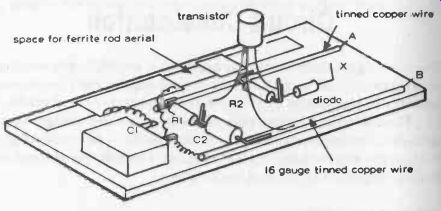
Fig. 20-2. The same circuit as Fig. 20-1 tackled by just connecting components
together via their open leads, and using bare wire for top and bottom lines.
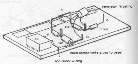
Fig. 20-3. Bonded mounting is similar to Fig. 20-2 but all components (except
transistors) are glued down to a base panel. Turn up ends of leads to form
connecting points.
BONDED MOUNTING
This is very similar to skeleton assembly except that individual resistors and capacitors are stuck down to a rigid base panel cut from plastic sheet. Use five-minute epoxy for gluing the components in place, Fig. 20-3.
This will produce a very strong bond in a few minutes. With the main components rigidly mounted you can then bend leads to produce the necessary connections and connection points for other components (e.g., transistors).
BUS-BAR ASSEMBLY
This is a neat and more "professional" way to tackle circuit construction. The top and bottom common lines of the circuit are laid down first by mounting two lengths of 16 gauge tinned copper wire in a sheet of plastic as shown. This will enable most of the resistors and capacitors to be mounted with one lead soldered in place. Complete the rest of the connections as for skeleton assembly, see Fig. 20-4.
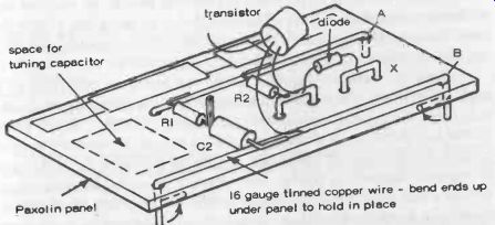
Fig. 20-4. Lay down the top and bottom lines in tinned copper wire, permanently
mounted on the panel. Shorter lengths of bare wire can be used for other common
connecting points. Complete by soldering component leads in place.
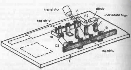
Fig. 20-5. All the connecting points are formed by tag strips or individual
tags mounted on the panel. Solder components to appropriate tags, and complete
with additional wiring as necessary.
TAGBOARD ASSEMBLY
More durable, and neater, than the previous methods, this involves mounting strips of solder tags (called tag strips at each of the main connecting points of the circuit layout.
These tags can be riveted or bolted through the panel. Individual components are then mounted between tags.
Any additional connections are formed by short lengths of wire between tags, see Fig. 20-5. More time is needed to construct a proper tagboard than with the previous methods, but complete tagboard stops are also available with up to 36 individual tags mounted in two parallel rows.
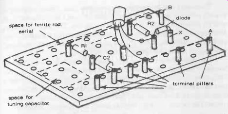
Fig. 20-6. Pegboard assembly is similar to Fig. 20-5 except that the board
is predrilled to accept terminal posts. Locate these posts at suitable points
to act as common connecting points. Connect components to posts, then complete
the additional wiring as necessary. Note: all these constructional drawings
show the same circuit-a simple single -transistor radio receiver with preamplifier.
Components required are:
Ferrite rod aerial with coupling coil
C1-0-500 pF tuning capacitor
C2--0.01 µF
R1-1 megohm
R2--2.2 k ohm
Diode--any germanium crystal diode
Transistor--any rf transistor
The circuit works off a 9 volt battery connected to A and B (polarity depends on whether the transistor used is a PNP or NPN type). For listening, connect high impedance phones to points X and B.
In case the aerial coil connections are not clear:
(i) The ends of the main coil connect to the two tags on the tuning capacitor (C1).
(ii) One end of the coupling coil connects to the common connecting point of R1 and C2
(iii) The other end of the coupling coil connects to the base lead (b) of the transistor
PEGBOARD CONSTRUCTION
You can buy special terminal pillars to press into the holes in ordinary pegboard and so set up connecting points for mounting components, Fig. 20-6. These terminals have screw connecting points, so you can avoid soldering components in place. The main disadvantage is that a fairly large panel size is needed, even for a simple circuit, with components well spread out. But it is an easy method of building experimental circuits.
There are various proprietary systems based on variations of the pegboard method. Vero-boards are panels with rows of copper strips, each strip being drilled with a number of holes either 1 mm (0.04 in.) or 1.3 mm (0.052 in.) diameter. Matching pins (Veropins)can be inserted in appropriate holes to form terminal pillars, and the copper strips cut as necessary to separate connecting points. Special tools are used for inserting the Veropins and for cutting the copper strips. Verostrip is a similar type of board except that the board is narrower (11/2 in. wide) and the copper strips run across the board with a break down the center. Components can be mounted across or along the strips.
Numerous solderless breadboards have also been developed where component leads are simply pushed into the boards where they are held by spring contacts. Contact points are arranged in parallel rows, with either a prearranged pattern of interconnection, or with basic busbar connections on top and bottom rows and others in common groups. Interconnection be tween groups can be made by wires pushed into spare points in each separate group.
The advantage of such a system is that, apart from avoiding soldering, circuits can easily be modified simply by pulling out a component and plugging into a different position.
For permanent circuits, the beginner will probably find pegboard assembly the best proposition after he has gained some experience in circuit construction - and confidence in being able to draw out component layouts accurately. The ultimate for all forms of compact circuit construction is, however, the printed circuit. Here components are mounted directly through holes in a plastic (or glass fiber) panel on which the circuit wiring has been reproduced by etching.
This is a separate technique on its own, but easy enough to learn--see Section 21.
General Rules
Connections should always be soldered, for best results. This applies even on pegboards fitted with screw-type terminal pillars. The one exception to the rule is solderless breadboards where connections are made by spring clips. In all cases, never rely on joints which are formed simply by twisting wires together.
Use a small electric soldering iron for making all soldered joints, and resin-cored solder (electrical grade). Never use an acid type flux on soldered joints in electrical circuits.
Transistors can be damaged by excessive heat. When soldering in place to a circuit, leave the leads quite long (at least 1 in.). Grip each lead with flat nose pliers behind the joint when soldering. The jaws of the pliers will then act as a heatsink, preventing overheating of the transistor. Once proficient at soldering, however, this precaution should not be necessary, especially in the case of silicon transistors.
The most common reason why a particular circuit will not work is because one or more connections have been wrongly made. This is far more likely to be the cause of the trouble than a faulty component. Always check over all connections after you have made them, using the theoretical circuit diagram as the basic reference. Also with transistor circuits, be sure to connect the battery the right way (as shown on the circuit diagram).