AMAZON multi-meters discounts AMAZON oscilloscope discounts
------------

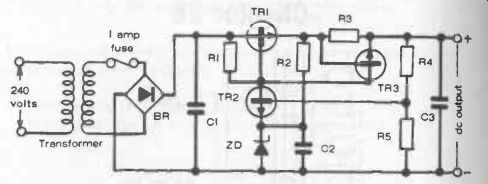
Fig. 26-1. Stabilized output dc charger for working off ac mains.
Components:
R1 - 680 ohms
R2 - 820 ohms
R3 - 1 ohm
R4 - 39 ohms for 6 volts dc output 180 ohms for 7.5 volts dc output 330 ohms for 9 volts dc output
R5 - 560 ohms
C1 - 1000 pF or higher value
C2 - 10 uF
C3 - 0.01 uF
T - 240/15 volt transformer (or 115/15 volt)
BR - bridge rectifier
TR1 - BD131
TR2 - BC108C
TR3 - BC108C
ZD - Zener diode
BZYbbC2V7
----------------
The application of a step-down transformer associated with a bridge rectifier and a smoothing capacitor to provide a low voltage dc supply from an ac mains supply has already been described in Fig. 8-5 Section 8. Rather more sophisticated circuits may be used where it is desirable to ensure a stable dc voltage, e.g., for operating an FM transistor radio from the ac mains instead of a battery.
A circuit of this type is shown in Fig. 26-1, the component values specified giving a stabilized dc output of 6 volts from 240 ac mains. The bridge rectifier following the transformer provides full wave rectification, smoothed by capacitor C1 in the conventional manner.
The input to output voltage is dropped across transistor TR1. The emitter voltage of transistor TR2 is set by the Zener diode at 2.7 volts. The output voltage is divided by R4, R5 and when the voltage across R5 is about 3.2 volts, TR2 begins to conduct.
This diverts some of the current flowing through R1 into the base of TR1 so that TR1 starts to turn off. Thus, since the base current, and the voltage drop across the collector -emitter junction of TR1, is controlled by TR2, the output voltage is stopped from going any higher than the design voltage.
Conversely, if a heavy load is applied to the output it will tend to cause a drop in output voltage and so also the voltage on the base of TR2 will tend to fall. The effect of this is that TR2 will start to turn off, allowing more current to flow into the base of TR1 which turns on to maintain the output voltage.
Voltage stabilization will be maintained until the output current rises to the order of 4-500 mA. At this point, the voltage across R3 becomes greater than the turn -on voltage of TR3, which will start to conduct. This will tap current from the base of TR1, causing TR1 to start to turn off, hereby reducing the output voltage, so that the current does not rise any further. In other words the circuit is automatically protected against over load, even down to short circuit conditions. In the latter case, the voltage will fall to almost zero, with the current still being maintained at 400-500 milliamps. The capacitors C2 and C3 are not strictly necessary, but are additional smoothing components.
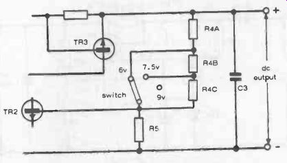
The circuit can be adapted to provide a number of different dc output voltages, selectable by switching. To do this, resistor R4 is replaced by a chain of resistors R4A, R4B, R4C, as in Fig. 26-2. The values given, together with the previous circuit component values, will provide select able outputs of 6 volts, or 9 volts, with voltage stabilized in each case up to a maximum current drain of 400-500 milliamps.

Fig. 26-2. Switching circuit for altering dc output voltage.
R4A - 39 ohms R4B - 150 ohms R4C - 150 ohms

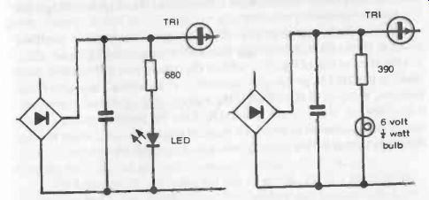
Fig. 26-3. Alternative arrangements for charging indicator lamps. A bulb of
appropriate voltage could be used in one of the output leads without a dropping
resistor.

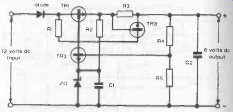
Fig. 26-4. Stabilized 6 volt dc charger working off 12 volt battery.
Components:
R1 - 680 ohms
R2 - 820 ohms
R3 - 1 ohm
R4 - 39 ohms
R5 - 560 ohms
C1 - 10 uF
C2 - 0.01 uF
TR1 - BC131
TR2 - BC108C
TR3 - BC108C
ZD - Zener diode BZY88C2V7 diode - IN4001 (or equivalent)
BATTERY CHARGERS
Either a bridge rectifier circuit, or the voltage -stabilized circuit just described can also be used for battery charging. In this case, smoothing is not so important, as the pre-sense of a certain amount of "ripple" in the dc is held to be beneficial for charging. Normally, however, at least one smoothing capacitor would be desirable in the charger circuit.
Since it is not necessarily evident whether a charger is working or not, an indicator lamp or ammeter is normally desirable in a charger circuit. A lamp merely indicates that the charger is "on" and the output circuit is working. It can be tapped directly across the circuit at any point, the preferred form of lamp being an LED since this draws minimal current, although a small filament bulb will do as well. An LED needs to be associated with a ballast resistor to drop the necessary voltage at this point; a filament bulb does not, but a resistor is needed to work as a voltage dropper if a 6 volt bulb is used in this circuit (see Fig. 26-3).
Note that an indicator lamp on the mains side of the transformer, or on the secondary side between the transformer and the bridge rectifier, would not necessarily confirm that the output was "working" with an output load connected.
In the case of a meter indicator, this would simply be an ammeter (or milliammeter, as appropriate) connected in series in one or another of the output lines.
DC INPUT CHARGERS
There is also a call for chargers which can charge low voltage batteries direct from another battery, such as a 12 -volt car battery. In this case, since the input is dc, a transformer cannot be used to set the required voltage, nor is a rectifier necessary.
Figure 26-4 shows a charger circuit designed to provide a stabilized 6 -volt dc output (charging voltage) from a 12-volt input supply. Essentially, it is the same as that of Fig. 26-1 without the transformer and rectifier, but a diode is included to protect the transistors in the circuit against reverse voltages. Working of the circuit is the same as that described previously, with automatic short-circuit protection. Like the previous mains circuit, too, it can be adapted to provide a range of output voltages, using exactly the same values for the chain of resistors as in Fig. 26-2.