AMAZON multi-meters discounts AMAZON oscilloscope discounts
Batteries may be divided into two main groups: primary batteries, where the electrochemical action is irreversible (once the battery has been discharged it cannot be reenergized); and secondary batteries, where the electrochemical action is reversible and they can be charged and discharged repeatedly (but not indefinitely), to be used over and over again.
Primary batteries are popularly called dry batteries; and secondary batteries are called storage batteries. These descriptions are not strictly correct, but they are convenient and widely accepted. In fact, all primary batteries have some form of "wet" electrolyte (usually in the form of a paste or jelly); and many secondary batteries may have so-called "dry" cells (implying the use of a non-liquid electrolyte). And just to show how general classifications cannot always be strictly correct, some types of primary (non -rechargeable) battery systems are, in practice, rechargeable!
DRY BATTERIES (PRIMARY BATTERIES)
A battery is made up of one or more individual cells. Each cell will develop a specific nominal voltage, depending on the battery system.
To build a battery with a higher voltage than that given by a single cell, two or more cells are connected in series.
The nominal cell voltage given by different "systems" is:
(i) carbon -zinc - 1.5 volts (ii) alkaline -manganese - 1.5 volts (iii) mercury - 1.35 or 1.4 volts (depending on the depolarizer used) (iv) silver oxide - 1.5 volts (v) zinc -air (a comparatively undeveloped system as yet) - 1.2 volts Choice of the best "system" is dependent on cost and utilization of the battery. Carbon-zinc dry batteries are by far the most popular because they are relatively cheap and readily available in a wide range of voltages and sizes, the latter governing the capacity of the battery, or the amount of electrical energy it can store.
Typical construction of a carbon-zinc cell is shown in Fig. 25-1. Higher voltage dry batteries may be produced by connecting two or more cells in series in a suitable pack, or more usually, by employing layer type construction, as shown in the second diagram.
The two main disadvantages of standard carbon-zinc cells (or batteries) are:
1. Under load (i.e., when current is being drawn from them), they are subject to a build-up of internal resistance due to "polarization," which has the effect of causing the output voltage to drop. The more rapid the rate of discharge, the more pronounced this voltage-drop effect.
------------------
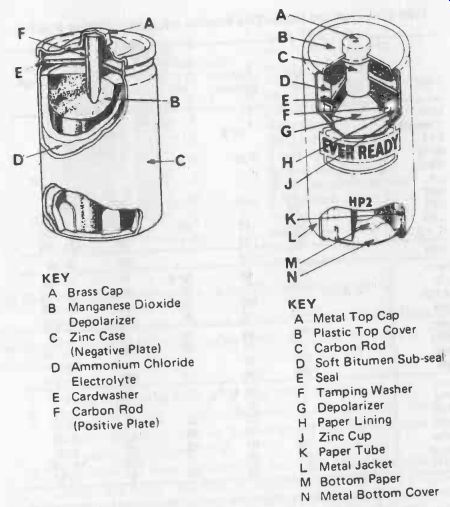
Fig. 25-1. Standard carbon-zinc cell (left) and HP cell (right).
KEY
A Brass Cap
B Manganese Dioxide Depolarizer
C Zinc Case (Negative Plate)
D Ammonium Chloride Electrolyte
E Card-washer
F Carbon Rod (Positive Plate)
KEY
A Metal Top Cap B Plastic Top Cover C Carbon Rod D Soft Bitumen Sub-seal E Seal F Tamping Washer G Depolarizer H Paper Lining J Zinc Cup K Paper Tube L Metal Jacket
M Bottom Paper
N Metal Bottom Cover
-------------------
2. The outer zinc case (normally enclosed in a paper or plastic jacket) is continually being eaten away by chemical attack, which accelerates as the cell becomes more and more discharged. If the battery is left in a flashlight, radio, battery -holder, etc, and left in a near-discharged or discharged state, the zinc casing will soon be eaten right through, allowing corrosive electrolyte to escape.
To a large extent, this can be avoided by using leakproof construction where the zinc case and cell bottom are enclosed by metal covers (usually tinplate). Even the leakproof carbon -zinc battery can suffer casing failure and leak if left in place when discharged, however, for there is always a tendency for the contents of the cell to swell and burst the casing when the cell is in a discharged state.
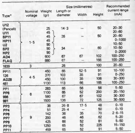
Table 25-1. Standard Carbon-Zinc Batteries (up to and including 9 volts). Type numbers shown in bold are World standards. Other types numbers are Eveready. See Table 25-2A and B for equivalents.
The high power, or HP, cell is an attempt to overcome both limitations.
It is invariably of leakproof construction and also employs a more effective depolarizing agent. As a result, it has a superior performance under high current drains, and also increased capacity. It is also more expensive, so an HP cell is not always a "best buy." In fact, the additional cost of HP cells is really only justified where the current drain is higher than that recommended for standard carbon -zinc cells.
And if positive leakproof performance is essential, another system is better (in particular, alkaline-manganese).
Table 25-1 is a useful guide both to the nominal voltage of standard sizes of carbon zinc batteries and their recommended operating range in terms of current drain. Capacities cannot be quoted for carbon-zinc dry batteries since the capacity of a particular size and type of cell can vary widely with different current drains, and the actual operating cycle. This capacity-or battery life-can really only be determined by practical experience in that particular usage.
--------------
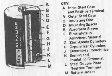
Fig. 25-2. Typical construction of a modern alkaline-manganese
cell.
KEY:
A Inner Steel Case and Positive Terminal B Outer Steel Case C Insulating Disc D Insulating Spacer E Absorbent Sleeve F Electrolyte in Absorbent Material G Zinc Anode Cylinders H Depolarizer Cylinders J Electrolyte Immobilizer K Sealing and Insulating Grommet L Steel Double Plate Negative Terminal M Battery Jacket
--------------------
ALKALINE-MANGANESE CELLS
Construction of a typical cylindrical alkaline -manganese cell is shown in Fig. 25-2. They are generally available only as single (1.5 volt) cells, and in a much more restricted range of sizes (see Table 25-2).
They are considerably more costly than carbon-zinc cells, but have three main advantages:
1. Voltage drop under load is far less pronounced.
2. They have a long, almost indefinite "shelf life" (i.e., there is virtually no loss of capacity in storage with fresh cells, and even with partly-discharged cells).
3. They have far more capacity for the same size compared with carbon-zinc cells, and thus a longer battery life under similar working conditions (size for size, about six times that of a standard carbon -zinc cell).

Table 25-2A. Carbon-Zinc Battery Equivalents
Table 25-2B. Equivalent 1.5 -volt Dry Cells.

Table 25-3
------------
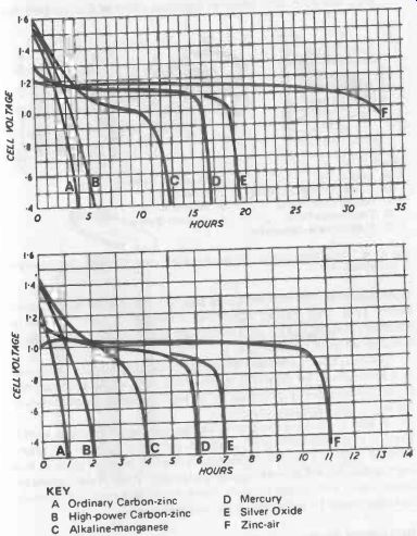
Fig. 25-3. Performance of AA size cells under moderate current drawn (top)
and higher current drawn (bottom).
KEY
A Ordinary Carbon-zinc
B High -power Carbon-zinc
C Alkaline -manganese
D Mercury
E Silver Oxide
F Zinc-air
---------------------
With this type of battery, it is also possible to quote actual capacities, as given in Table 25-3. They can be regarded as a direct substitute for equivalent carbon -zinc cells where their advantages outweigh the higher cost. They are particularly suitable for constant heavy-load (i.e., high current drain) duties for which the carbon -zinc battery is least suited (Fig. 25-3).
Standard alkaline -manganese batteries are basically primary batteries. Contrary to popular belief they can be recharged at low current rates corresponding to 1/10th of their capacity figure, e.g., a 750 mAh capacity cell at 750/10 = 75 mA. Full charge time with such a current would be 12-14 hours. There is a danger of a cell exploding if charged at too high a rate, or for too long a time, however, unless it is a vented type. Vented alkaline manganese batteries are now available which are recognized as true secondary batteries and specified as rechargeable.
---------
KEY
A Double Top B Plastic Sealing Grommet C Wound Zinc Anode D Zinc Anode Pellet E Electrolyte in Absorbent F Synthetic Barrier G Inner Can H Synthetic J Adaptor Sleeve
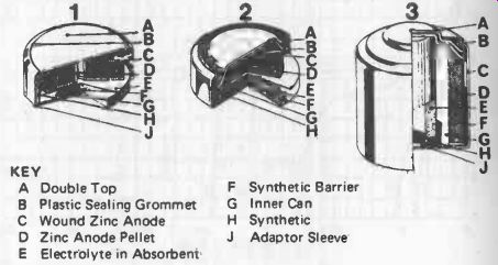
Fig. 25-4. Typical construction of mercury cells: 1. wound anode, 2. pellet
-type, 3. cylindrical type.
--------------
MERCURY CELLS
Mercury dry cells have an extremely high capacity for their physical size and weight. To take advantage of this characteristic, they are normally made in diminutive "button" sizes, but larger cells of this type are also produced, see Fig. 25-4.
Each cell develops a lower voltage than either of the two previous types described, but this voltage is largely unaffected by load (current drain). Thus, after a slight initial drop, a mercury cell will continue to maintain a constant voltage until almost fully discharged, when the voltage will drop off quite rapidly.
This can be a considerable advantage in many applications. It can also be a disadvantage, for there is no means of assessing how far a mercury cell has been discharged by measuring its "on load" voltage. It simply comes to the end of its useful life suddenly.
It also has some other minor disadvantage (apart from high cost!).
There is an appreciable drop in capacity if operated at temperatures below about 5°C (40° F), and, at freezing point, the cell becomes more or less inert, although it will recover again on warming up. It is also not suitable for use in contact with copper or copper alloy, so contacts used with mercury batteries should be nickel plated (or stainless steel).
SILVER-OXIDE CELLS
Silver-oxide cells have similar characteristics to mercury cells, with a higher nominal cell voltage which remains substantially constant under load. They also have superior low-temperature characteristics, but cost is higher than a mercury cell and availability limited.
SECONDARY BATTERIES
The familiar lead-acid battery was widely used in the early days of radio as a low -voltage battery. The only type of rechargeable battery which has a significant application in present-day electronics is the modern nickel-cadmium battery. It is the one type of secondary battery system in which "gassing" can be eliminated on charging, so it can be constructed in fully sealed -cell form (although many types are, in fact, constructed with re-sealing vents as a precaution).
---------------
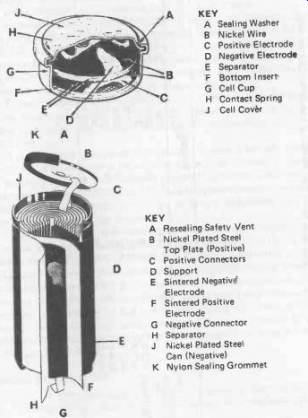
Fig. 25-5. Typical nickel-cadmium button cell (top) and cylindrical cell (bottom).
KEY
A Sealing Washer B Nickel Wire C Positive Electrode D Negative Electrode E Separator F Bottom Insert G Cell Cup H Contact Spring J Cell Cover
KEY
A Resealing Safety Vent B Nickel Plated Steel Top Plate (Positive) C Positive Connectors D Support E Sintered Negative Electrode F Sintered Positive Electrode G Negative Connector H Separator
J Nickel Plated Steel Can (Negative)
K Nylon Sealing Grommet
-----------------------
Table 25-4
Nickel -cadmium batteries offer numerous advantages - no deterioration during storage in either charged or discharged state (except that a charged cell with suffer a loss of about 20 percent of its capacity a month); charge/recharge cycle life of at least several hundred and possibly thousands (depending on actual use); suitability for high discharge rates (and high charge rates with vented cells); robustness; wide operating temperature range (-40° C to + 60° C); and suitability for operating in almost any environment.
Disadvantages are high initial cost (which is generally recoverable in long cycling life), and the fact that the nominal voltage per cell is only 1.2 volts. However, the discharge characteristics are substantially "flat," i.e., output voltage is maintained regardless of load. To ensure a full recharge being given, the favored technique is first to discharge the cell or battery fully under controlled conditions and then give a full charge.
Construction of a typical nickel–cadmium "button" cell is shown in Fig. 25-5. Button cells are produced with capacities ranging from about 0.1 Ah up to 1.75 Ah-see Table 25-4. Battery packs are made up by welding separate cells together in a stack of the required number (the whole stack then usually being in a shrunk -fitted plastic sleeve). Larger capacities are provided by cylindrical and rectangular nickel-cadmium cells.
Vents are fitted to all nickel-cadmium cells intended for use with high current drains and/or high discharge rates. These vents are of the re sealing type so that under normal operating conditions the cell is virtually a sealed type.
A problem with nickel-cadmium cells can be that it is virtually impossible to solder connections to the cells. However, cells (and battery packs) are produced with tags spot-welded to each end (and at individual tapping points on a battery, if required) to which soldered connections can be made.
Without such tags, connections to a cell or battery pack would normally have to be made via spring contacts.
Specifications for nickel-cadmium batteries may quote capacities at either the 10-hour or 5-hour (discharge) rate. The difference can be significant, as the effective capacity of a given battery is dependent on discharge rate-higher discharge rates resulting in a loss of capacity. Equally, any maximum current rating for a nickel -cadmium battery can be somewhat arbitrary. Most cells can withstand higher current drains than the specified maximum, but continual cycling under such working conditions can substantially reduce the actual number of useful life cycles.
Special nickel-cadmium cells with sintered electrodes are designed for operation with very high current drains.
GENERAL BATTERY RULES
1. To increase the voltage of a battery, increase the number of cells connected in series to make up the battery.
For a battery of given voltage:
required battery voltage No. of cells required = volts per cell If the number of cells so calculated is not a whole number, use the next whole number up.
For example:
Battery voltage required is 9 volts Cells to be used are nickel-cadmium, volts per cell 1.2.
No. of cells required = 9 1.2 = 7.5 cells
Therefore, make up the battery from 8 cells connected in series. (The actual battery voltage will then be 8 x 1.2 = 9.6 volts. If necessary the additional voltage can always be dropped in a circuit by using a dropping resistor).
2. To increase the capacity of a battery, connect two (or more) batteries of the required voltage in parallel. Two batteries connected in parallel will halve the current drain from each battery, thus doubling the capacity. Basically, in fact, the capacity of the original battery is multiplied by the number of similar batteries connected in parallel.