AMAZON multi-meters discounts AMAZON oscilloscope discounts
One of the principal uses of a capacitor is as a coupling device capable of passing ac but acting as a block to dc. In any practical circuit, there will be some resistance connected in series with the capacitor (e.g., the resistive load of the circuit being coupled), This resistance limits the current flow and leads to a certain delay between the application of a voltage to the capacitor and the build-up of charge on the capacitor equivalent to that voltage. It is this "charge voltage" which blocks the passage of dc. At the same time, the combination of resistance with capacitance, generally abbreviated to RC, will act as a filter capable of passing ac frequencies, depending on the charge-discharge time of the capacitor, or the time constant of the RC combination.
One of the principal uses of a capacitor is as a coupling device capable of passing ac but acting as a block to dc. In any practical circuit, there will be some resistance connected in series with the capacitor (e.g., the resistive load of the circuit being coupled), This resistance limits the current flow and leads to a certain delay between the application of a voltage to the capacitor and the build-up of charge on the capacitor equivalent to that voltage. It is this "charge voltage" which blocks the passage of dc. At the same time, the combination of resistance with capacitance, generally abbreviated to RC, will act as a filter capable of passing ac frequencies, depending on the charge-discharge time of the capacitor, or the time constant of the RC combination.
TIME CONSTANT
The formula for calculating the time (T) is quite simple;
T = RC where T = time constant in seconds
R = resistance in megohms
C = capacitance in microfarads
(It can be noted that the same numerical value for T is given if R is in ohms and C in farads, but megohms and microfarads are usually much more convenient units.)
The time constant is actually the time for the voltage across the capacitor in an RC combination to reach 63 percent of the applied voltage (this 63 percent figure being chosen as a mathematical convenience). The voltage across the capacitor will go on building up to almost (but never quite) 100 percent of the applied voltage, as shown in Fig. 6-1.
The time-constant factor refers to the duration of time in terms of the time factor, e.g., at 1 (which is the time factor of the RC combination) 63 percent full voltage has been built up, in a time equal to 2 x the time constant, 80 percent full voltage; and so on. After a time constant of 5 the full (almost 100 percent) voltage will have been built up across the capacitor.
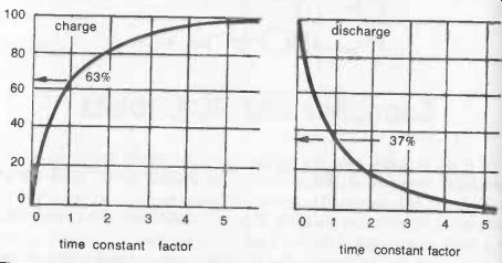
Fig. 6-1. Percentage voltage across capacitor related to time when being charged
(left) and discharged (right).
The discharge characteristics of a capacitor take place in essentially the inverse manner, e.g., after a period of time equal to the time constant the voltage across the capacitor will have dropped 100-63 = 37 percent of the full voltage and so on.
In theory, at least, a capacitor will never charge up to full applied voltage; nor will it fully discharge. In practice, full charge, or complete discharge, can be considered as being achieved in a period of time equal to five time constants. Thus, in the circuit identified with Fig. 6-2, closing switch 1 will produce a "full" charge on the capacitor in 5 x time constant seconds. If switch 1 is now opened, the capacitor will then remain in a condition of storing a voltage equivalent to the original applied voltage, holding this charge indefinitely if there is no internal leakage. In practice, it will very slowly lose its charge, as no practical capacitor is perfect, but for some considerable time it will remain effectively as a potential source of "full-charge" voltage. If the capacitor is part of a high -voltage circuit, for example, it is readily capable of giving an electric shock if touched for some time after the circuit has been switched off.
To complete the cycle of charge -discharge as shown in the second diagram of Fig. 6-1, switch 2 is closed, when the capacitor discharges through the associated resistance, taking a finite amount of time to complete its discharge.
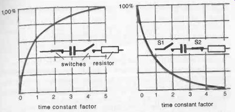
Fig. 6-2. Closing switch 1 allows capacitor to charge right up in a time equal
to 5 time constants. It then takes a similar period to discharge fully through
a load resistor when switch 2 is closed.
Figure 6-3 shows a very simple circuit working on this principle. It consists of a resistor (R) and capacitor (C) connected in series to a source of dc voltage. As a visual indication of the working of the circuit, a neon lamp is connected in parallel with the capacitor. The lamp represents virtually an open circuit until its threshold voltage is applied, when it immediately conducts current like a low resistance and glows (see Section 10 for more about neons). The voltage source for this current must therefore be above that of the neon turn-on voltage.

Fig. 6-3. Simple neon flasher circuit (note the symbol for a neon lamp). The
values of the resistor (R) and capacitor (C) determine the flashing rate.
When this circuit is switched on, the capacitor starts to build up a charge at a rate depending on the time constant of R and C. The lamp is fed by voltage developed across the capacitor. Once this reaches the turn -on voltage of the lamp, the lamp will switch on and cause the capacitor to discharge through the neon gas, causing it to glow.
Once the capacitor has discharged, no more current flows through the lamp and so it switches off again until the capacitor has built up another charge equivalent to the turn -on voltage, when it will discharge through the lamp, and soon.
In other words the neon lamp will flash at a rate determined by the time constant of R and C.
is:
Using the component values shown, the time constant for the circuit T = 5 (megohms) x 0.1 (microfarads) = 0.5 seconds.
This is not necessarily the actual flashing rate of the circuit. It may take a period of more than one time constant (or less) for the capacitor voltage to build up to the neon turn-on voltage-more if the turn-on voltage is greater than 63 percent of the supply voltage; less if the turn-on voltage is less than 63 percent of the supply voltage.
It also follows that the flashing rate can be altered by altering the value of R or C, either by substituting different values calculated to give a different time constant; or with a parallel -connected resistor or capacitor.
Connecting a similar value resistor in parallel with R, for example, would double the flashing rate (since paralleling similar resistor values halves the total resistance).
Connecting a similar value capacitor in parallel with C would halve the flashing rate.
This type of circuit is known as a relaxation oscillator.
Using a variable resistor for R it could be adjusted for a specific flashing rate. It can also be extended in the form of a novelty lighting system by connecting a series of RC circuits, each with a neon lamp in cascade, each RC combination have a different time constant-Fig. 6-4. This will produce random flashing of the neons in the complete circuit.
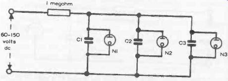
Fig. 6-4. Random "cascade" flasher circuit. Any number of lamps
can be connected in this way and will flash in random order.
CAPACITORS IN AC CIRCUITS
As far as ac is concerned, the fact that the applied voltage is alternating means that during one half cycle the capacitor is effectively being charged and discharged with one direction of voltage; and during the second half of the ac cycle, charged and discharged with opposite direction of voltage.
Thus, in effect, ac voltages pass through the capacitor, restricted only by such limitations as may be applied by the RC time constant which determines what proportion of the applied voltage is built up and discharged through the capacitor.
At the same time, the capacitor will offer a certain opposition to the passage of ac through reactance (see Section 3), although this does not actually consume power. Its main influence is on frequency response of RC circuits.
SIMPLE COUPLING
Coupling one stage of a radio receiver to the next stage via a capacitor is common design practice. Although the capacitance is apparently used on its own, it is associated with an effective series resistance represented by the "load" of the stage being fed--Fig. 6-5. This, together with the capacitor, forms an RC combination which will have a particular time constant. It is important that this time constant matches the requirements of the ac signal frequency being passed from one stage to the other.

Fig. 6-5. Basic function of a coupling capacitor is to pass ac signals and
block dc signals. It will also pass undulating dc signals.
In the case of AM radio stage, the maximum of signal likely to be present is 10 kHz. The "cycle" time of such a signal is 1/10,000 = 0.1 milliseconds. However, to pass this frequency each cycle represents two charge/discharge functions as far as the coupling capacitor is concerned, one positive and one negative. Thus the time period for a single charge / discharge function is 0.05 milliseconds.
The RC time constant necessary to accommodate this working needs to be this value to pass 63 percent of the applied ac voltage-and preferably rather less to pass more than 63 percent of the applied voltage.
These figures can give a clue as to the optimum value of coupling capacitor to use. For example, the typical input resistance of a low power transistor is of the order of 1, 000 ohms. The time constant of a matching RC coupling would be 0.05 milliseconds (see above), giving the requirements:
0.05 x 10 = 1,000 x C or C = 0.05 x 10^-9 farads = 0.50 pF (or preferably rather less, since this would ensure more than 63 percent voltage passed).
In practice, a much higher capacitance value would normally be used; even as high as 1µF or more. This will usually give better results, at the expense of efficiency of ac (in this case rf) transmission. (An apparent contradiction, but it happens to work out that way because the load is reactive rather than purely resistive.) What simple calculation does really show is that capacitive coupling becomes increasingly less efficient with increasing frequency of ac signal when associated with practical values of capacitors used for coupling duties.
FILTER CIRCUITS
A basic RC combination used as a filter circuit is shown in Fig. 6-6.
From the input side, this represents a resistor in series with a capacitive reactance, with a voltage drop across each component. If the reactance of the capacitor (Xc) is much greater than R, most of the input voltage appears across the capacitor and thus the output voltage approaches the input voltage in value. Reactance is inversely proportional to frequency, how ever, and so with increasing frequency the reactance of the capacitor decreases, and so will the output voltage (an increasing proportion of the input voltage being dropped by the resistor).

Fig. 6-6. Basic filter circuit. It will block ac frequencies higher
than the cut-off frequency of the combination of R and C.
As far as effective passage of ac is concerned, there is a critical frequency at which the reactance component becomes so degraded in value that such a circuit starts to become blocking rather than conductive, i.e., the ratio of volts out/volts, starts to fall rapidly. This is shown in simplified diagrammatic form in Fig. 6-7. The critical point, known as the roll-off point or cut-off frequency (f) is given by:
f _ 1 27T RC where R is in ohms C is in farads 71- = 3.1416 But RC, as noted previously, is equal to the time constant of the RC combination. Hence: = 1 277- T where T is the time constant, in seconds.
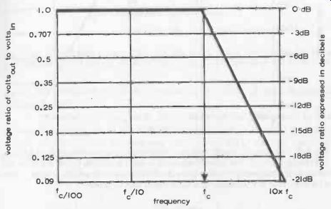
Fig. 6-7. Simplified diagram of how the ratio of volts;,,/ volts out drops
rapidly as the cut-off frequency of a filter is exceeded. All signals below
the cut-off frequency are passed without attenuation.
The performance of such a filter is defined by its cut-off frequency and the rate at which the volts in/volts out ratio falls above the cut-off frequency.
The latter is normally quoted as -(so many) dB per octave (or each doubling of frequency)-see Fig. 6-8 which shows the relationship between dB and volts in /volts out ratio, and also the true form of the frequency response curve.
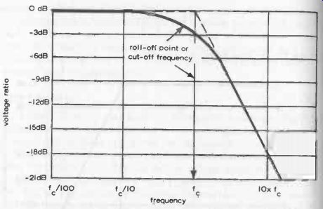
Fig. 6-8. The actual "roll -off point on the frequency response curve
of a filter is not sharply defined. The cut-off frequency is really a nominal
figure and generally taken as the frequency at which there is a 3 decibel loss
or a volts in/ volts out ratio of 0.707. This is equivalent to a 50 percent
loss of power.
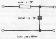
Fig. 6-9. Simple scratch filter circuit. Any combination of component values
giving a product of RC = 1600 will work.
LOW-PASS FILTERS
Circuits of this type are called low-pass filters because they pass ac signals below the cut-off frequency with little or no loss or attenuation of signal strength. With signals above the cut-off frequency, there is increasing attenuation. Suitable component values are readily calculated. For example, a typical scratch filter associated with a record player or amplifier would be designed to attenuate frequencies above, say, 10 kHz-Fig. 6-9.
This value represents the cut-off frequency required, i.e., Any combination of R (in ohms) and C (in farads) giving this product value could be used.
HIGH-PASS FILTERS
High-pass filters work the other way around. They attenuate frequencies below the cut-off frequency, but pass frequencies at and above the cut-off frequency with no attenuation. To achieve this mode of working, the two components in the circuit are interchanged--Fig. 6-10.
This type of filter is again commonly associated with record player circuits, incorporated to eliminate low -frequency noise or "rumble" which may be present. The design cut-off frequency must be low enough not to interfere with bass response, and so the value chosen is usually of the order of 15 to 20 Hz. Exactly the same formula is used to determine the cut-off frequency, hence, using a design value of 20 Hz:
RC = 125
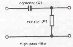
Fig. 6-10. (Right) high-pass or "rumble" filters cut off low frequencies
but pass high frequencies.
A typical value for the product RC in this case would be 125.
Again, any combination of R (in ohms) and C (in farads) giving a product of 125 would work.
In practical circuits, such filters are normally inserted in the preamplifier stage, or in the amplifier immediately in front of the tone-control circuit. For Hi-Fi systems, the type of filter circuits used are considerably more complicated than the ones described.