BY FAR THE MOST POPULAR tape machine at the time of writing is the cassette deck. With current design techniques allied with the new tape formulations the cassette deck has been elevated into the true hi-fi region (see Cassette Tape Recorders--our previous title by the publishers of this guide) . The cassette deck works in partnership with a hi-fi system - providing an extra program source while also making it possible to record from radio and disc records for future replay. The less expensive cassette recorder which contains its own amplifier and loudspeaker and the inexpensive portable machines cannot be regarded as high quality or hi-fi.
Cassette Convenience
The cassette deck is taking the place of the reel-to-reel tape deck, which was the only hi-fi tape source available a few years ago. However, there are still many enthusiasts whose interest lies in very high quality recording and replay.
These buffs are more interested in the reel-to-reel deck. Certainly the quality potential of this type of machine is in advance of the cassette deck, while the wider recording tracks and the higher tape speeds· greatly facilitate editing of tapes. The convenience of the cassette system, though, is valued highly by many people, particularly where the requirement is for direct recording from one program source - say FM radio or disc - for direct replay later. The compact cassette - pioneered by Philips - is far more convenient to handle and store than the disc record.
More pre-recorded cassettes are also becoming available at improved quality than hitherto with Dolby encoding for an almost 10 dB noise reduction on replay when correctly Dolby decoded. To retain the advantage of the cassette while maintaining the quality potential of a wider track and faster tape speed, we have recently seen the advent of the ELCASET and similar type of cassette housings . Parameters The items or parameters of a tape machine are virtually the same whatever the format . What differs is the actual value of a parameter . The following example specification, therefore, could be for any tape machine - cassette, reel-to-reel or ELCASET. As we run through the parameters it will be explained how they can differ over the various formats.
Tape Deck Parameters
Input sensitivity for 0-VU recording level
1 kHz: Line input: 80mV
DIN input: 0 ·8mV
Microphone input: 0 · 1 m V
Input overload threshold 1kHz: Line input: > 10V DIN input
100mV Microphone input: 40mV
Output at 0-VU 1kHz across 47k-ohm o
400 mV (output level control when fitted at maximum) from line; headphone monitoring "' 200mV across 8 ohms and
400mV across 200 ohms
Output overload threshold 1kHz and line:z3V
Meter reading for 200 nWb/ m flux: 0 to +3 VU (see text)
Harmonic (third) distortion with recommended tape: 0-VU recording level : 0.3%
+6VU recording level: 2.5% intermodulation (3rd-order) distortion at 7 and 8kHz equal amplitude driving signals:
-5VU: 5%
-3VU: 8%
Head amplifier/head overload threshold: 420nWb/m flux induction for 3% 2nd harmonic distortion 1kHz S/N ratio (CCIR/ ARM - see Section 3) ref. 200 nWb/m: Recommended Fe tape: 49dB Dolby off; 59dB Dolby on Recommended Cr or FeCr tape: 51 dB Dolby off; 61dB Dolby on Frequency response recommended tape: 20nWb/ m flux: to 15kHz (-3d B) 200nWb/m flux: to 7kHz (-3d8)
Wow and Flutter (DIN peak-weighted, COO cassette) : 0.1 % Fast spooling time C60 cassette: 100 seconds Stereo separation 1kHz and 0-VU: 40dB These are the parameters which our lab has determined over a number of years to be of the maximum value and which have a good degree of correlation to the listening experience. They apply essentially to a well designed cassette deck. With a good quality reel-to-reel deck some of the parameters will be better, as explained in the text which follows .
Input Sensitivity
When making a recording it is often necessary to ensure that the VU meter peaks towards 0-VU on loud sounds. It is desirable for this to happen without the recording level control having to be set at maximum. The input sensitivity parameter reveals the r.m.s. signal voltage required at 1kHz to secure 0-VU recording level with the recording level control at maximum.
The signal available for recording is generally higher in level than the input sensitivity voltage. Thus, to achieve the 0-VU condition on peaks the recording level control does not need to be set at maximum.
Input Overload Threshold
However , if the source signal is very much greater than the input sensitivity voltage there is a possibility that the input preamplifiers will be overdriven on very loud sounds , causing distortion. When this is likely to happen, the recording level control will only require a small displacement from its 'zero' setting to obtain the 0-VU recording level on the meters. It is highly undesirable to operate like that . The plan would then be to attenuate the input signal so that 0-VU on peaks occurs when the level control is turned about half or three-quarters on.
Alternatively, one could use a different tape deck input whose sensitivity is closer to the source signal voltage. You will see from the example specification that the so-called 'line' input has the lowest sensitivity (requires the highest voltage for 0-VU recording level) . You will also see that this input is less likely to overload than the DIN or microphone input (e.g., it will accommodate a greater voltage to the overload threshold) . This is the best input to use, therefore, when the source signal voltage is strong enough.
DIN Input
The DIN input is deliberately designed for relatively high sensitivity (small input voltage for 0-VU). This is because it is designed to 'match' the recording output signal delivered by hi-fi receivers and amplifiers themselves equipped with a DIN socket . The signal here depends on the input load of the tape deck presented to the output, the common DIN value being approximately 1-mV for each lk-ohm of input load of the tape deck. Thus, if the load is, say, 10k-ohm, the signal voltage from the DIN socket on the receiver or amplifier will be round 10mV. This will allow the recording level control to be sensibly retarded to secure 0-VU recording level (the recording level control will thus be set to provide about 10 to 12dB of signal attenuation) . However, because the DIN input overloads earlier than the line input, a strong signal applied to the DIN socket is much more likely to cause distortion than when applied to the line sockets. Wherever possible, the line inputs should be used in preference to the DIN input; but where the amplifier or receiver feeding the tape deck is itself equipped with a DIN socket, then you will usually have no choice but to use the DIN socket.
Some amplifiers and receivers give a choice of line ('phono' type) sockets and a DIN socket. If the tape deck is also equipped with line outputs in addition to DIN, always use the line sockets . In this way you will be more likely to achieve the best possible recording and replay quality. The nature of the DIN socket system tends also to roll-off the higher audio frequencies
Spectrogram
This test is usually made at a relatively low-frequency of 333-Hz or, perhaps, 40Hz, and the spectrogram in Fig. 4. 1 shows a good example. Here the horizontal divisions are 200Hz each and the vertical divisions 10-dB each. In this case the driving signal (sinewave fundamental) is 400Hz and, of course, the third-harmonic 1,200Hz.
The second-harmonic is 800Hz but this is barely seen because it is below the noise floor. The spectrogram, however, does show fourth-harmonic at 1,600Hz and fifth-harmonic at 2,000Hz. The third-harmonic predominates and is at a level of approximately 30dB below the fundamental, thereby corresponding to 3 % . The amount of distortion produced is also affected by the nature of the tape (its formulation) and its biasing; also by the machine electronics and head parameters (see the Cassette Tape Recorders guide). Cassette machines tend to produce more distortion at a given recording flux than reel-to-reel machines using wider tape tracks and higher tape speed.
To establish how much more distortion is produced with the VU meter peaking above 0-VU, a similar measurement is commonly made also at + 3 or +6 VU. The example parameter values typify a good quality cassette deck operating with top-flight tape.
Intermodulation Distortion
Non-linearities at higher frequencies are best measured in terms of intermodulation distortion (IMD) by using two driving signals for recording and then analyzing the adjacent sidebands (IM products) . A spectrogram showing such an analysis is given in Fig. 4.2. Here the two driving signals are at 9.5 and 10 - 5kHz, the first pair of adjacent sidebands thus falling at .5 and 11.5kHz. The two driving signals each have the same amplitude but, owing to the machine's equalization, the sidebands differ in amplitude.
The dB ratio or percentage distortion is obtained by comparing the vector sum of the two IM sidebands with the vector sum of the two driving signals.
In this case, the two driving signals show at the same amplitude at 0-db (vector sum +/-3dB) on the vertical scale, while the lower sideband is -13dB and the upper sideband -15dB, corresponding respectively to 22.38 % and 17.78 %, the vector sum thus being 28.58 %, corresponding to 20.2 % distortion.
It should be noted that this is an extreme case where the recording level was deliberately set high to show the severity of this type of high-frequency distortion when over-recording. The test is sometimes made with equal amplitude driving Signals of 7 and 8 kHz at recording levels of -5-and -3 VU, as in the example specification. It should be noted that the peak amplitude of a two tone composite signal is 3dB above the peak amplitude of one of the driving signals . Hence the reason for making this measurement at the lower VU meter readings.
The values given in the example specification are fairly typical of a good quality-cassette deck operating-with a tape of the best formulation. At higher frequencies and higher recording levels the distortion can be significantly higher. Reel-to-reel machines exhibit less IMD;

Fig. 4.1 (left) : Spectrogram showing third-harmonic tape distortion.
Scale 200Hz per horizontal division and 10dB per vertical division. See
text for further information.
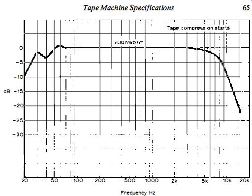
Fig. 4.2 (right) : Spectrogram showing intermodulation distortion from
a two-tone driving signal. Scale 2kHz per horizontal division and 10dB
per vertical division . See text for further information.
Head Amplifier/Head Overload Threshold
When the signal current in the head winding, or the head signal level applied to the head input preamplifier, goes beyond a certain value, severe non-linearity sets in and distortion results. From the replay aspect, this overload threshold parameter can be important, particularly when heavily recorded tapes or musicassettes are played through the machine.
It has been suggested that the peak flux on some pre-recorded cassettes can be as high as 6dB above Dolby level, or 400nWb/m peak. Clearly, then, it is important that there is sufficient headroom to accommodate this peak flux level . If the overload threshold occurs at a lower flux value, then more distortion than necessary will occur on replay.
Similarly, when recording at peaks above 0-VU the record head (often the same head as used for replay) can veer towards magnetic saturation and hence introduce distortion on the recorded signal . This problem is being aggravated by the new high energy, high coercivity tapes because the magnetic field required for full modulation and complete erasing is approaching the saturation limits of the heads themselves, particularly with the tapes that require the high Cr bias level for the best results, including the new pure iron tapes.
Some of the ferrite heads appear to be more easily saturated than those of hard permalloy. A more recent development is the Sendust head* which is capable of yielding high flux levels before magnetic saturation sets in. Such heads are now being found in certain JVC, Philips and other machines.
Overload Parameter
The 'overload' parameter, found in our more recent reviews and reports, is measured by applying an increasing input while analyzing the output. Tape and head distortion is essentially third-harmonic, while head amplifier distortion is generally more second-harmonic. By applying an input which raises the tape flux to 6dB above Dolby (40nWb/m) we can thus determine whether the rise in distortion is due to magnetic or amplifier overload effects.
A machine which produces no more than 3% second-harmonic at 400n Wb/m would be unlikely to cause trouble under normal operating conditions . However, if the third- and other odd-order harmonics rise swiftly before this flux level, head saturation might well be troublesome.
S/N Ratio
We are now using CCIR/ ARM weighting for tape machine S/N ratios referred to the 200nWb/m Dolby level for cassette machines. A new tape is recorded at the Dolby level and then, with the machine still in the record mode but with the input signal removed, the same tape is run for several minutes with no signal being recorded but, of course, with the erase system operative.
For the latter part of the process, the appropriate signal input of the machine is correctly loaded and the recording level controls set to the position corresponding to 0-VU recording level when the input signal is 20dB above the input sensitivity. The measurement thus takes into account erase noise and the noise produced by the record input pre-amplifiers.
With CCIR/ ARM weighting (see Section 3), a good Fe tape will give a S/N ratio of approaching 50dB with Dolby off and a Cr (and FeCr which requires 70 uS equalization) tape approaching 53dB. The ratio is improved with a noise reduction system, being about 9· 5dB better with Dolby and JVC's ANRS. Dynamic Range Referred to the output for 3 % distortion and CCIR/ ARM weighting, a good machine with a good tape will have a dynamic range at 333Hz of 55 dB Fe and 58dB Cr and FeCr without noise reduction. At high-frequency, based on IMD, ranges of 48dB and 50dB respectively can be expected. Almost an extra 10-dB is achieved by noise reduction, which makes the cassette medium quite attractive for hi-fi recording and replay.
Reel-to-reel machines using wide tracks can achieve, at least, an extra 3dB dynamic range.
Frequency Response
The frequency response of a hi-fi cassette deck need be no worse than that of the FM system of broadcasting! A reel-to-reel machine will have an overall frequency response which is substantially better. Depending on record level, a well designed cassette deck with top-grade tape will give a response within 1 dB from 30Hz to 15kHz. A reel-to-reel machine can have the same response characteristic up to 35kHz or higher.

Fig. 4.3: Frequency response sweep at 20nWb/m recording level, showing
tape compression.
The factor which determines the high-frequency response is essentially tape compression (assuming that the replay head is equipped with a very fine gap of not much more than a micrometer) . As told in the Cassette Tape Recorders guide, tape compression occurs progressively with rise in frequency, and it is signified by a steep rise in distortion.
The curve in Fig. 4.3 shows a frequency sweep taken at a 1kHz flux level of 200nWb/m, where it is seen that tape compression starts to show round 4 to 5kHz, the response then falling. A distortion measurement made at the compression frequency would reveal a significant rise compared with, say, the distortion at 1kHz. This is a factor of the tape itself rather than the machine.
The curve in Fig. 4.4 shows a sweep of the same machine but this time at a flux level of 20nWb/m (20dB below the first) . Here the response will be seen to hold steady up to 15kHz. Just above that frequency there is a swift roll-off which, in general , is deliberately provided by a 19kHz notch filter fitted to prevent 19kHz pilot tone from poorly pilot-tone-suppressed FM stereo tuners from adversely affecting the operation of the Dolby noise reduction; also to prevent FM stereo pilot tone and tape machine bias oscillator 'beats' from causing whistles and 'burbles' on the recording.
It will be seen that this response characteristic has quite a bit in common with that of an FM tuner. The undulations at the bass end are caused by head characteristics, as explained in the Cassette Tape Recorders guide.
Some people complain that such a frequency response can only be achieved at relatively low, high-frequency recording level . This is true, of course, but, in our opinion, it is not as bad as sometimes projected by equipment reviewers who seem to forget that the 'energy' of real music at high-frequency is well below the 'energy' content at the low-middle and middle frequencies, anyway! The spectrogram in Fig. 4.5 is a slow sweep of the 1812 Overture taken from a well recorded disc using a JVC Xl cartridge. The horizontal scale is 5kHz per division and the vertical scale 10-dB per division. Notice how dramatically the effective 'energy' diminishes with increasing frequency.
Thus , when your meter is peaking towards 0-VU on music signal, most of the energy of the signal contributing to this lies below the 200nWb/m tape compression onset frequency.
Wow and Flutter
Slow and fast cyclic variations of tape motion are respectively known as wow and flutter. The former can endow the reproduction with a 'drunken' effect, while the latter can impair the subtle definition and ambience of the music.
Many parameters measure the two effects collectively via a weighting network proposed by the German DIN people (see page 116 of the Audio Technician's Bench Manual). This is known as DIN Peak-Weighted Wow and Flutter, and is the parameter chosen for the example specification at the start of this section.
There is reason to believe that separate readouts of wow and flutter would give more subjectively meaningful information, and we are inclined to agree with this train of thought.
The wow and flutter depends not only on the mechanical quality of the machine's tape transport, but also on the mechanics of the C-zero (the cassette itself). Some C-zeros tend to wow and flutter more than others while, on the other hand, some machines are more critical of the C-zero mechanics than others.
The parameter should assess the wow and flutter at the start, middle and end of a cassette, at the places where there can be substantial differences in torque, and the 'average' value should be given. A top-flight cassette machine will give a readout with a good cassette of less than 0.1%, while less exacting machines may go as high as 0.25% - sometimes much higher at times as the cassette torque varies and when the machine mechanics are not particularly accommodating. Much above 0.2% 'average' cannot be classified as hi-fi. A reel-to-reel machine running at the higher speeds can yield far better wow and flutter figures than the average cassette deck. On the other hand, some of the best cassette decks return values well approaching those of reel-to-reel machines.
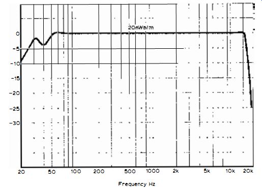
Fig. 4.4: Frequency response sweep at 20nWb/m recording level , showing
'flat' high frequency response.
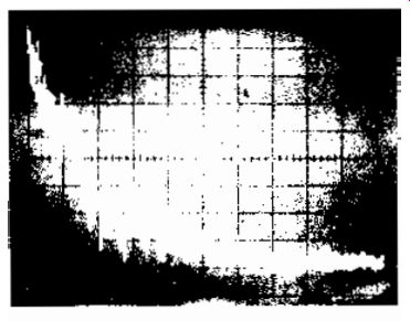
Fig. 4.5: Spectrogram of the 1812 Overture on slow sweep, showing how
the effective 'energy' of music falls off with frequency. Scale 5kHz per
division horizontally and 10dB per division vertically.
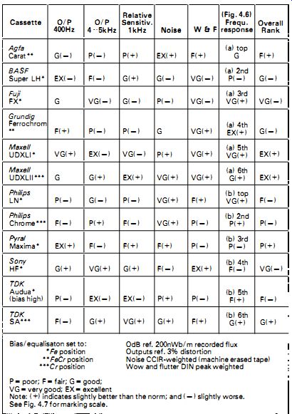
TABLE 4. 1 TAPE CASSETTE/ CASSETTE MACHINE COMPATIBILITY EVALUATION (Cassette
Deck-Aiwa 180)
Fast Spooling Time
This is merely the measure of time taken for a cassette of stated length (usually C60) to fast spool from left-to-right and right-to-left. An average time is 100 seconds for a C60 cassette.
It has been suggested that a too rapid action will tend to accelerate the oxide from the tape base when the wind suddenly halts . However, the best fast-spooling machines have automatic torque control to avoid this or other damage to the tape.
Stereo Separation
As with f. m. stereo radio, this is a measure of the signal in one stereo channel breaking into the other channel . The measurement is often made at 1kHz (sadly, with cassette decks the separation tends to diminish fairly swiftly with increasing frequency) by recording the track of one channel at 200nWb/m or 0-VU, then playing the tape back and measuring the level on the signal on the non-recorded track relative to the level of signal on the recorded track.
The result is generally given as a dB ratio, and a good value is 40-50dB ref. 0-VU recording level when the breakthrough signal is measured by way of a 1kHz bandpass filter to defeat noise error.
At 10kHz, the separation of a cassette machine may be as low as 20dB, depending on head and circuit design. Reel-to-reel machines can generally do better than this.
Tape Type
As will now be appreciated, the overall performance of a tape machine is strongly influenced by the type of tape used. Any specification should thus include the type of tape with which the machine's parameters were measured.
To give some idea of how the performance of a cassette machine can differ with different tapes , we show in Table 4. 1 the measured parameters of the (a) (b)
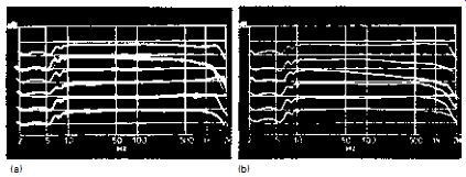
Fig. 4.6: Frequency response sweeps associated with Table 4. 1, (a) first
six tapes and (b) second six tapes. Scale 20Hz -20kHz log sweep and 5dB
per division vertically.
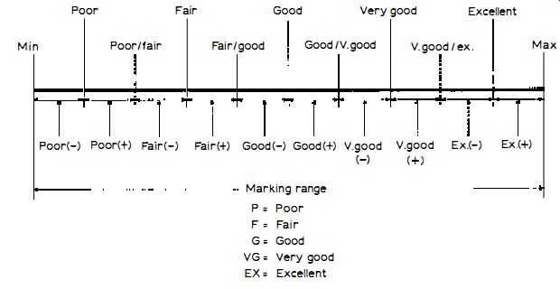
Fig. 4. 7: Standard marking scale of author's lab, used for compiling
the results in Table 4.1 . excellent Aiwa 1800 cassette deck with 12 different
tapes *, with the frequency response sweeps at 20n Wb/m given in Fig. 4.6
at (a) and (b) . The results have all been statistically analyzed, but
instead of presenting actual figures, we have given here the results in
terms of poor (P), fair (F) , good (G) , very good (VG) , and excellent
(EX) with ± deviations according to our standard marking scale shown in
Fig. 4. 7.
In a practical situation, of course, one would take account of the price of the tape, for the very best results are usually obtained from the more expensive formulations . It must also be stressed that while a certain tape on one machine may give 'poor' results , on a different machine the results may be much better; which is precisely the point we are making! Some of the tapes included have since been improved, including the Pyral formulations (with the introduction of the new Super ferrite) and the TDK SA. Agfa have also introduced a new Fe formulation (SFD1), while BASF are currently marketing an LH1 Fe formulation and a new Cr tape. There are also a number of other excellent tapes introduced since the time of preparing this example compatibility chart.
*From the work of our lab published in the Hi-Fi For Pleasure magazine, June l977
= = = =