A. GENERAL CONSTRUCTION. Power resistors generally are composed of one or more of the following parts: 1-A resistive conductor 2-A support for the resistive conductor 3-Terminals for connecting to the resistive conductor 4-A means of protecting the resistive conductor These separate parts, in turn, are mechanically combined into a finished resistor.
B. RESISTIVE CONDUCTORS. Resistive conductors for power resistors are made of alloys or metals in wire or ribbon form. Several of the more common forms of resistive conductors are illustrated in Figure 2-1. The particular form selected depends primarily on the requirements of the particular resistor application and secondarily on the individual manufacturer's experience with the various materials used in conjunction with his individual production processes.
In actual practice, when choosing a material for a resistive conductor, the resistor design engineer endeavors to obtain:
1-A material whose resistivity will allow for selection of good mechanical strength, permitting the proper wire diameter or ribbon thickness to ensure against microscopic flaws, hard-spots, or breakage due to mechanical strain.
2-A material that has stable characteristics over the intended operating and manufacturing temperatures.
3-A material that is capable of being readily manufactured.
4-A wire or ribbon that is readily usable with the support, terminals and protective materials.
5-A resistive conductor that is economical from the standpoint of material cost.
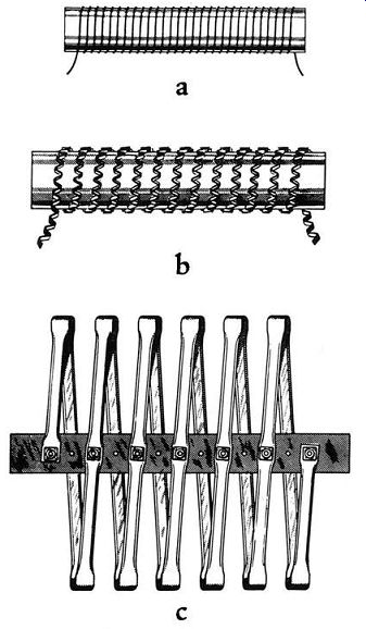
Figure 2-1a. Typical Forms of Wire or Ribbon Resistive Conductors.
a-Round wire-single layer, b-Reflexed ribbon-wound on edge, c Channel shaped ribbon.
Figure 2-1b. Typical Forms of Wire or Ribbon Resistive Conductors d-Steps in forming channeled ribbon from flat alloy resistance ribbon, e-Oval shaped ribbon coils, f-Coiled wire.
Table 2-1 lists the more important alloys and metals used as resistive conductors together with their basic properties. Before selecting the material for the resistive conductor the following properties should be thoroughly understood: resistivity, temperature coefficient of resistance, mechanical strength, maximum working temperature, corrosion, aging and temperature coefficient of expansion.
1. Resistivity--By definition the resistivity of a material is the reciprocal of its conductivity. In more general terms, resistivity of a material is the direct-current resistance of a sample of the material having specified dimensions, the resistance being measured in ohms. The resistivity of resistive conductors is usually expressed as ohms per circular-mil-foot ( Ohms/CMF). Table 2-1 indicates that the resistivity of alloys and metals is from 10 to 800 ohms/CMF, allowing a wide range from which selection can be made. Where low resistance values are needed materials having a low value of resistivity are selected. The fact that resistance is inversely proportional to the cross-sectional area of the material should also be considered. For example, if we consider two resistive conductors of equal length and made of the same material, the one having the larger cross-sectional area will have the lower resistance.
2. Temperature Coefficient of Resistance--The ohmic resistances of most pure metals increase greatly with an increase in temperature as shown by the formula: R12 = R11 [1 + a (t2 - t1)] resistance in ohms at increased tempera ture R11 resistance in ohms at original temperature t2 temperature in cc t1 original temperature in cc a temperature coefficient of resistivity …
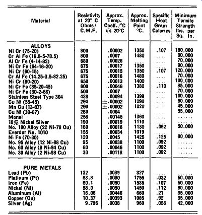
Table 2-1 Properties of Various Metals and Alloys
A copper conductor has a temperature coefficient of resistivity (a) of approximately 0.004 at twenty degrees centigrade. This value represents an increase of resistance of 0.4 percent per degree centigrade. Because power resistors operate at several hundred degrees above zero, it is apparent that the metals or alloys selected as resistive conductors must have much lower temperature coefficients of resistance than pure metals.
This is necessary to maintain fairly constant resistance values under various load conditions and ambient temperatures.
In most instances the temperature coefficient of resistivity is positive--i.e., resistance increases with increase in temperature. In a few cases the material has a negative coefficient of resistivity--i.e., resistance decreases with increase in temperature.
As indicated in Table 2-1, most materials used as resistive conductors have positive temperature coefficients of resistivity in the order of 1.6 x 10^-4, or about 1/24-th that of copper. Using the formula, the calculated increase in resistance is approximately 5 percent for a 300°C rise. However, since the entire resistive conductor is not operating at the maximum temperature rise ( 300°C), the actual increase in resistance will be only about 3 to 4 percent.
In applications where a 5 percent change in resistance is unsatisfactory, the usual procedure is to use materials having approximately zero temperature coefficient. Less change also can he obtained by lowering the operating temperature of the resistor.
If these methods are used to secure close resistance tolerances, two factors must be considered. First, alloys with negative temperature coefficients of resistance and good aging and stability characteristics usually have resistivities equal to about one-half those ordinarily utilized. Thus the wire size necessary to obtain the same resistance must have one-half the area of those generally used. This, in many instances, necessitates the use of extremely fine wire sizes. Because of the low mechanical strength of the wire, such resistors become difficult to manufacture. Second, it may also mean changing the embedding coating which necessitates lowering the maximum permissible temperature rise. This, in turn, results in a larger resistor unit or use of a multiplicity of units.
Large units or assemblies of small units will naturally require more space and will be more costly than units operating at higher temperature rises.
In other applications, the resistor must have a higher temperature coefficient than normal. Materials are avail able that have temperature coefficients of about 45 x lo-4 or approximately 20 percent higher than that of copper.
3. Mechanical Strength--Resistive materials should have sufficient strength so that the smallest wire diameter can be wound with sufficient tension without damage, i.e., wires must be capable of being stressed without exceeding the elastic limit. They must also be able to withstand the effects of expansion and contraction caused by heating and cooling during operation.
Comparative minimum tensile strengths as measured in pounds per square inch for the various resistive materials are given in Table 2-1. When converted into ounces per circular mil, the tensile strength of No. 180 alloy becomes only about one-half an ounce per circular mil.
From the example given, it is evident that materials with high tensile strength become more important where small wire sizes are used. Tensile strength is one of the limiting factors in determining the smallest diameter wire that can he used safely. On standard, power type resistors the minimum wire size is 0.001 inch in diameter.
4. Maximum Working Temperature--The maximum working temperature of the resistive conductor is considerably lower than its melting point. This is the temperature above which hare wire should not he used.
5. Corrosion--Each of the alloys listed in Table 2-1, is subject to more or less corrosion. In use, a film forms on the surface. The corrosion product may be protective; that is, it may prevent further corrosion of the metal underneath by sealing it from the air, moisture, or other damaging elements. However, most corrosion products are non-protective; that is, they are hygroscopic, flaky, porous, etc. To prevent corrosion, some form of protection, such as vitreous enamel in which the resistive conductor is embedded, is recommended.
6. Aging--High temperature and time have a cumulative effect on the resistive conductor. This leads to the gradual growth of the grain structure and general mechanical weakening. While most of the alloys suit able for use as resistive conductors have excellent aging characteristics, aluminum-bearing alloys, in general, are not recommended for operation at temperatures normally encountered with power type resistors.
7. Temperature Coefficient of Expansion--Because most materials used as resistive conductors expand when their temperatures increase, their temperature coefficient of expansion becomes an important and often critical design factor. This is particularly true when embedding coatings are used as the protecting medium. Basically the problem resolves itself into one of matching rather than one of actual control of the coefficient of expansion of the wire or ribbon. Selection of ceramics and vitreous enamels having the proper (or compatible) coefficients of expansion is the most practical means of effectively neutralizing the deleterious effects of wire or ribbon expansion and contraction. On un-embedded ( open or bare type) resistors, the coefficient of expansion of the resistive conductors should be as small as possible. This precaution should be taken to prevent loosening of the coils of wire or ribbon under normal operating temperatures.
C. RESISTIVE CONDUCTOR SUPPORTS.
Supports for resistive conductors, the second basic part of a resistor, are sometimes referred to as "cores" or "bases". They function, as their name implies, primarily to support the resistive wire or ribbon.
Supports for resistive conductors must of necessity be insulators because the wire or ribbon will be in contact with the supports. Moreover, the insulation properties of the supports must be maintained at the operating temperature of the resistor. In most designs, this requirement prohibits the use of ordinary organic insulations, if the full efficiency of the resistor, in so far as space and economy of materials is concerned, is to he maintained.
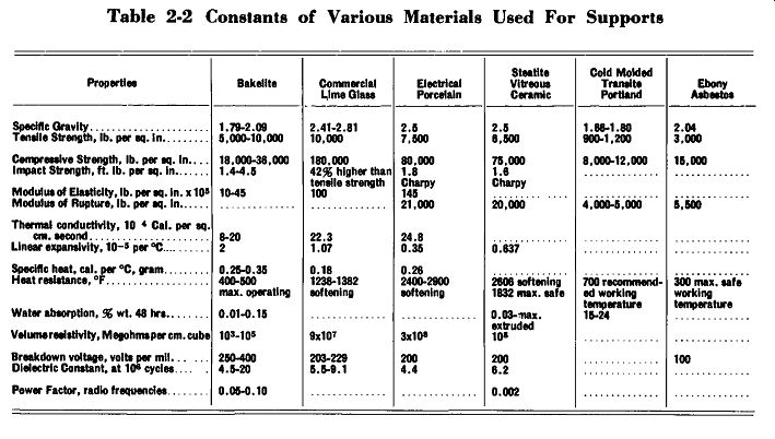
Table 2-2 lists the usual materials for resistive conductor supports. They
include: asbestos sheet, glass, porcelain, slate, steatite and miscellaneous
cold molded or vitrified inorganic materials. The insulating proper-ties of
some of these materials while decreasing due to increase in temperature, are
sufficiently high for commercial use.
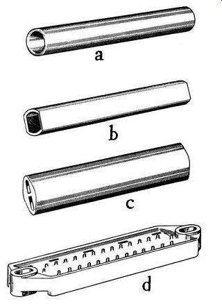
Figure 2-2a. Typical Forms of Supports for Resistive Conductors a-Tubular
ceramic core, b--Tubular ceramic core-with flat sides, c-Oval shaped ceramic
strip, d-Flat molded ceramic-rectangular shape.

Figure 2-2h. Typical Forms of Supports for Resistive Conductors e-Flat molded
ceramic-circular shape, £-Ebony asbestos strip, g Grooved ceramic strip, h-Pressed
steel pan-vitreous enamel insulated.
It should he realized that materials listed as inorganic and with suitable heat resistant qualities, have the undesirable characteristic of low mechanical strength.
However, by the judicious design and control of manufacturing processes, the strength of available materials can be held at a maximum. Other support design pre cautions that should he taken to maintain ample mechanical strength are:
1--Make the unit as small as possible.
2--Avoid cantilever construction.
3--Avoid long beam lengths on small diameter tubes.
The material's coefficient of expansion should he compatible with that of the resistive conductor and the protective coating. This is necessary to prevent cracking, peeling or layer separation under temperature changes.
It is also imperative that binders used in molding materials, organic compounds, and cements, be unaffected by operating temperatures. There should he no weakening of the structure or softening or cracking of the material.
The shape of the resistive conductor support, which may take the form of rods, cylinders, strips, etc., is determined largely by the type of resistor and ratings required. Several common shapes for resistive conductor supports are shown in Figure 2-2. Other support forms are illustrated in photographs accompanying Section III, TYPES OF RESISTORS. Of all the forms shown, the most widely used for power resistors are cylinders of various sizes. These are made by extrusion of ceramic material which is then cut to length and fired at high temperatures to vitrify the material. This process, explained in more detail in Section VI, results in a support that is straight, strong and uniform in size and shape.
In tubular resistors, since the circumference of the supporting core determines the length of wire that can he wound on a given length unit with specified pitch, close core tolerances are essential to secure accurate resistors.
----------
Table 2-2 Constants of Various Materials Used For Supports
---------------
D. TERMINALS.
Resistor terminals, Figure 2-3, perform several important functions. They afford a means of electrical connection to the resistive conductor. Terminals, there fore, should have excellent conductive and corrosion resistant qualities. Because of their close proximity to the resistive conductor which operates at high temperatures, connections must not be adversely affected by these temperatures, either by the formation of insulating oxides or other changes in physical characteristics.
Terminals may serve to hold the resistive conductor in place. For example, on tubular wire wound resistors, the ends of the resistive conductor are secured to terminal bands and thereby anchored in place. Since the terminals are partially embedded in the protective coating ( vitreous enamel) it is important that the thermal expansion characteristics of the terminal material be "matched" with that of the embedding material. This is necessary to prevent cracking of the coating and unsatisfactory sealing of the unit about the terminals.
On tubular resistors the connection point or joint between the resistive conductor and the terminal should be silver brazed. The high melting point of silver solder is particularly advantageous because it precludes any possibility of the joint softening when the resistor is operated at rated load. The joint formed by silver brazing also provides a superior mechanical and electrical connection.
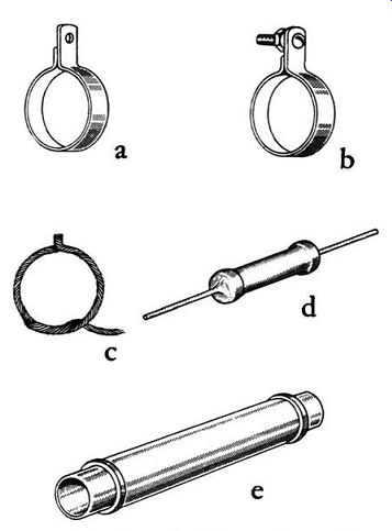
Figure 2-3a. Typical example of Resistor Terminal Connections a-Tab terminal,
b-Screw type, c-Stranded wire, d-Axial wire solid, Ferrule or band.
Figure 2-3b. Typical examples of Resistor Terminal Connections f-Edison screw base, i;-Clamp type, h-Adjustable clamp.
Certain terminals sometimes serve as a means of mounting the resistor. Terminals should have ample mechanical strength to avoid damage when connecting external wiring. Where external connections must be soldered to the resistor terminals, materials should be selected that can be readily soldered. Terminals designed for soldering connections are generally tinned during manufacture as an aid in soldering.
The exact method of securing terminals to the sup port and resistive conductor, and the determination of the best type terminal, depends essentially on the type of finished resistors. Further details on the common types of terminals are discussed in Section III, TYPES OF RESISTORS. E. PROTECTIVE COATINGS. Because of the detrimental effects that adverse atmospheric conditions have on the resistive conductor, some forms of power resistors, usually wire-wound types, are fully sealed and protected by some kind of embedding material. The coating applied depends on the resistor operating temperature, extent of protection needed, and service requirements as to thermal shock, moisture, humidity and insulation.
The wide variety of protective coatings includes: vitreous enamels, organic and inorganic cements, organic paints and varnishes, and silicone paints and varnishes.
Because coatings used vary with each manufacturer, only general requirements will be discussed in subsequent paragraphs.
1. Thermal Conductivity--When the resistive conductor (wire) is embedded, the heat generated by the wire must be conducted to the air either through the resistor core or through the protective coating. The operating temperature of the wire is determined by the degree to which the embedding material and core are able to conduct the heat. Therefore, materials with high thermal conductivity characteristics should be chosen. If materials having poor thermal conductivity qualities are used, the life of the resistor is shortened.
2. Radiation and Convection--Once the heat is con ducted to the surface of the resistor, it is dissipated by radiation and convection. The thermal radiating or emissive qualities of materials vary greatly and are independent of air circulation. As the resistor surf ace temperature increases, the effect of heat dissipation by radiation become increasingly important.
Convection resulting from circulation of air over the resistor surface carries a large portion of the heat away.
The amount of heat dispersed by convection depends essentially on the temperature and rate of flow of the cooling air and on the resistor surface area.
3. Thermal Shock--Protective coatings must be capable of withstanding thermal shock, that is, sudden marked changes in ambient temperature such as encountered in service. Excellent thermal shock characteristics though necessary for continuous duty become even more important where the resistors are used in intermittent duty circuits where high momentary overloads are encountered.
4. Thermal Expansion--Thermal expansion characteristics of the protective coating should be favorable, i.e., "matched" to the thermal expansion characteristics of all other resistor parts. This condition must exist over the entire operating temperature range of the units.
Coatings should also adhere firmly to the wire, core and terminals without peeling, cracking or flaking during operation.
5. Mechanical Protection--One of the main reasons for embedding the wire, as mentioned previously, is to supply adequate mechanical protection, especially when fine wire sizes are used. The coating not only protects the resistive conductor, but also the terminal band and silver-brazed joint between the wire and the terminal hand. Protective coatings provide a secondary function, that of holding the wire and terminals securely in place.
6. Corrosion-Protection against the damaging effects of corrosion is another vital function of embedding materials. In general, coatings used should be resistant to moisture and acid fumes, and for some applications salt spray. To accomplish this, coatings should he free from cracks, crazes, pinholes and other openings that would allow corrosive atmospheres to reach the wire.
7. Insulation-Protective coatings must provide adequate insulation between turns of the winding to prevent short circuits during high voltage surges.
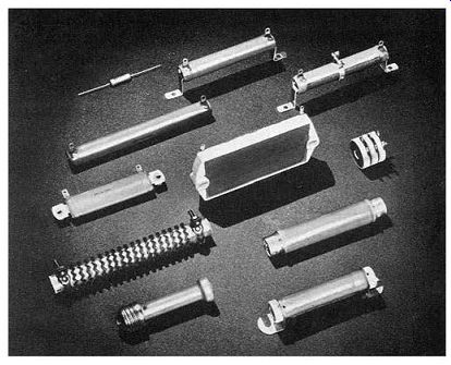
Figure 2-4. Typical Vitrohm wire-wound power resistors.