A. VITROHM TUBULAR RESISTORS.
Today's standard resistors for power applications are Vitrohm resistors, developed by the Ward Leonard Electric Co. over half a century ago. These vitreous enameled, wire- and ribbon-wound resistors are manufactured in a wide variety of types and sizes to meet virtually every industrial, commercial and military power resistor requirement. Of all the types available Vitrohm units of the tubular type are most in demand.
1. Construction--A Vitrohm resistor, Figure 3-1, consists basically of a tubular ceramic core on which the resistive conductor is wound and the ends of which are secured to metal terminals by means of spot welding.
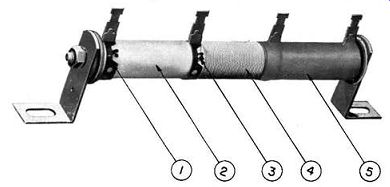
Figure 3-1. Vitrohm tubular resistor construction
1-Terminals and band, 2-Tubular ceramic core, 3-Spot welded or silver brazed joint, 4-Alloy resistive conductor, 5-Vitreous enamel protective coating.
The resistive conductor and the band portion of the terminal are then completely covered by vitreous enamel. Although the general construction of other manufacturers' products is similar to that of a Vitrohm resistor, there are major differences in method of manufacture. The following analysis of each of the basic components which go into the manufacture of the finished Vitrohm resistor will show why Vitrohm resistors are industry's standard power resistor.
a. Ceramic core--The tube for the Vitrohm resistor is a high density, low porosity (less than ½ percent moisture absorption maximum), high dielectric-strength body with a thermal coefficient of expansion selected to have the correct relation to the expansion of the Vitrohm enamel. The ceramic core is cylindrical with smooth surf ace and square ends.
b. Terminals--Terminals of the Vitrohm resistor are of high-heat-resistant, high-tensile-strength alloy especially selected to insure proper expansion, good adherence to the enamel and to provide the strongest anchorage to the ceramic core. They are clamped securely to the core by welding.
c. Resistive conductor--Resistance wire used in the Vitrohm resistors is especially manufactured to Ward Leonard specifications to insure uniformity and ability to withstand excessive overloads. A wide variety of alloys is employed depending upon the service requirements for each type of resistor.
d. Joint--The junction between resistive conductor and terminal is of extreme importance in any resistor.
The Vitrohm resistor joint is made by spot welding or silver brazing to insure a permanent, positive, low-resistance junction between resistive conductor and terminal.
e. Protective Coating--Vitrohm enamel ( developed and manufactured exclusively by Ward Leonard) is a hard, tough, moisture and acid resisting vitreous enamel with high heat conductivity. It completely seals the resistive conductor from all contact with injurious elements.
At the same time it provides excellent mechanical protection to the resistive conductor, the joint and the terminals. It is fired at high temperature during the manufacturing process. In operation, resistors are never subjected to such conditions. In other words, the finished Vitrohm resistor has already withstood, during manufacture, a more severe test than will ever be encountered in normal service.
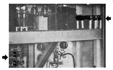
Figure 3-2. Vitrohm Power Resistors installed in WOR-TV transmitter, N. Bergen,
N. J. Vitrohm Ferrule Terminal Resistors with high voltage mounting, upper
right, are for bleeder purposes.
The Vitrohm enamel that hermetically seals the resistive conductor, also possesses characteristics which withstand rapid changes in temperature. For example, units operating at 340°C can he immediately placed in a chamber at -55°C without any chipping or crazing of the enamel or damage to the element. Vitrohm enamel can equally withstand the effects of prolonged exposure to high humidity and electrolysis. Vitrohm resistors will stand up in an atmosphere of 95 percent relative humidity with a potential gradient of 120 volts D. C. between the resistive conductor and a metal plate to which the resistor is bolted without supplementary insulation. They will withstand a repeated heating and cooling cycle from 340° to 20°C without any effect upon either the enamel or the resistive conductor.
Ward Leonard produces its own Vitrohm enamel and ceramics. The majority of other vitreous enamel resistor manufacturers buy their enamel and ceramics from outside sources. Two factors are important here: First, Vitrohm enamel and ceramics are developed and manufactured expressly to match each other and to be compatible with the wire and terminals. Only by con trolling the enamel and ceramic and selecting the proper wire and terminal materials can the proper relationships of the coefficients of expansion be maintained. Second, by making each component, the uniformity of quality is assured. Every batch of enamel is tested for thermal expansion, softening point, flow point and texture before release for production. The same control applies to the Figure 3-3. Basic forms of Vitrohm tubular resistors 1-Fixed, 2-Adjustable, 3-Tapped, 4-:llulti-section.
ceramic material from which the resistor cores are extruded.
2. Forms-Four basic forms of Vitrohm tubular resistors, Figure 3-3, are available to the design engineer.
(1) Vitrohm fixed resistors are resistors of a single winding with tab, screw, flexible-lead, ferrule, Edison base, or fire-panel terminals.
(2) Adjustable Vitrohm resistors have terminals the same as fixed resistors but, in addition, have the wire winding exposed in a path along one side so that an adjustable band may be affixed and moved along the length of the exposed wire to adjust resistance as desired.
(3) Tapped Vitrohm resistors are fixed units with an extra terminal or terminals at predetermined points along the tube. The terminals, at desired points, are provided for voltage division or adjustment.
(4) Multi-Section Vitrohm resistors are arranged similarly to tapped units except that with this arrangement two or more electrically independent resistor sections may be obtained with a single resistor assembly.
Two terminals are required for each section and a space without resistance winding separates each independent section.
3. Terminals--Determination of the best type terminal for a Vitrohm resistor should be based on the following considerations:
(1) Rating, type and physical size of the resistor.
(2) Method of connection soldering, machine screws, fuse clips, etc.
(3) Method of mounting.
(4) Allowable space and accessibility.
(5) Size and type panel wiring.
(6) Creepages and clearances to ground or other "live" parts.
(7) Ambient temperature and other application conditions such as vibration and excessive humidity.
Figure 3-4 illustrates several types of terminals for Vitrohm Resistors.
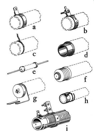
Figure 3-4. Typical Types of Vitrohm Resistor Terminals a-Tab, b-Screw-type
tab, c-Flexible wire lead, d-Ferrule, e-Axial, f-Edison base, g-Bracket, h-Band,
i-Adjustable band.
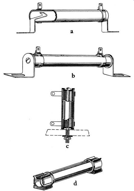
Figure 3-5a. Typical Methods of Mounting Vitrohm Tubular Resistors a-Push-in
spring clips, b--Through bolt-horizontal, c-Through bolt vertical, d-Ferrule-fuse
clips.
Figure 3-5b. Typical Methods of Mounting Vitrohm Tubular Resistors e-Self-supporting, f-Edison Base, g-Through bolt vertical with mica washers.
a. Tab or lug terminals are recommended where the wiring leads must he soldered. These metal tabs, usually pre-tinned for easy soldering, are made in standard widths from fir inch to ½ inch and with various size holes to accommodate different wire sizes. The wider, heavier weight tabs should he used with the larger size tubes.
b. Screw-type tab terminals are intended for use where heavy leads are brought to the resistor and are fastened directly by fastening between the nuts that accompany the screw connections. Like solder tabs those of the screw type are available in a number of sizes to facilitate use of various size control circuit wiring and solder or solderless lugs.
c. Pigtail or flexible-lead terminals are especially suited for connecting the resistor directly to other circuit components by means of the flexible leads. Leads are ordinarily tinned and uninsulated.
d. Ferrule terminals should he selected for ease of interchangeability where it is necessary to change the resistance value in a circuit. Ferrule terminal resistors are supplied for use with 0-30 ampere or 31-60 ampere, 250 volt fuse clips or 31-60 ampere, 600 volt fuse clips.
e. Axial terminals serve two purposes, namely, a means of connection and a means of mounting the resistor. The solid wire leads are normally tinned for convenience in soldering.
f. Resistors with Edison base terminals are screwed into standard lamp sockets. They are advantageous in applications such as load hanks, battery charging equipment and other apparatus requiring an easy means of changing resistance.
g. Another terminal used where interchangeability is necessary, such as on fire and signal panels, is the bracket terminal. Leads from the resistive conductor are silver brazed to the slotted brass brackets. The brackets, which also serve as a means of mounting the resistor, are held in place hy a through bolt that is insulated from the brackets hy means of porcelain bushings. They may also he equipped with anchors and cemented into the ends of the resistor.
h. Band ferrule terminals, like the ferrule type, require fuse clips for connection and mounting purposes.
i. Adjustable bands for use in Adjust ohm or bare side resistors should he specified where one or more intermediate resistance values are needed, or where the circuit resistance must be changed from time to time.
Screw-driver type or bakelite insulating knob type adjustable bands are available.
4. Mountings--Many of the selection factors discussed under "Terminals" must also he analyzed in choosing the proper type mounting for a resistor. For example, the number and type of resistors together with the space allowance and application conditions all must be considered.
Several typical ways of mounting Vitrohm tubular resistors are shown in Figure 3-5. For the average commercial or industrial application push-in spring clips are used and are generally considered satisfactory. A second method of mounting single tubes horizontally is by means of through bolts, mica washers, centering washers and L-shaped brackets. For vertical mounting through bolts and centering washers are used. On high voltage applications mica washers or ceramic bushings should be used. Where accessibility and quick replacement is desirable, ferrule (fuse clip), Edison base or bracket terminal mountings should be used. For mounting two or more resistors, through-bolt bracket mountings should he used. Through-bolt bracket mountings should always he specified where the equipment will be subjected to shock or vibration. Special bracket mountings are required for high-shock military requirements.
5. Enclosures--Several typical enclosures for housing single or multiple resistor units are illustrated in Figure 3-6. These enclosures are constructed of expanded or perforated metal and are rectangular, oval or circular in shape. Most types can be equipped with removable metal tops, BX connectors, external terminal connections and other features to meet application requirements.
Besides protecting resistors against mechanical dam age, enclosures prevent accidental contact with "live" parts.
When mounting enclosed resistors, locations where ventilation is restricted should be avoided. When resistors are enclosed, singly or in groups, their nominal watt rating must be reduced. See page 62 for information on derating for enclosures.
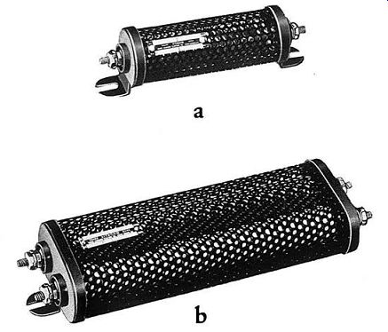
Figure 3-6a. Typical enclosures for Vitrohm Resistors a-Circular shaped perforated
metal, h--oval shaped perforated metal. Figure 3-6b. Typical enclosures for
Vitrohm Resistors c-Adaptor disclosure, d-Rectangular metal mesh with screw terminals,
e-Rectangular metal mesh with BX connector.
6. Ratings--The free-air watt ratings of Vitrohm tubular resistors range from 5 to 218 watts per unit.
Resistance values from 0.2 to 1,750,000 ohms are obtainable.
Nominal core lengths are from 1 to 12 inches, while outside diameters range from -r.\ to 11/a inch. Inside diameters of Vitrohm tubes are listed in Table 3-1. The type of tube is designated by a letter, i.e., Z, 0, WX, etc. Each tube of a specified outside diameter is available in several standard lengths as shown in Section V, page 124.
----------- Table 3-1 Inside Diameters of Vitrohm Ceramic Tubes (inches)
Note: Above tolerances do not make allowances for longitudinal curvature.
------------
7. Resistance Tolerance--On Vitrohm fixed and adjustable resistors from 1 ohm to maximum possible ohms, the standard resistance tolerance, measured from one end terminal to the other, is + 5%. The tolerance on adjustable resistors is measured without the adjustable band. For values below one ohm and for tapped resistors the standard tolerance is -+- 15%. Other tolerances as low as + 0.5% are available at increased cost. On tubes having short nominal lengths close tolerances should be avoided wherever possible.
8. Performance Data--Accurate resistor performance data is particularly valuable for determining the useful life of a resistor under average as well as adverse application conditions. Such information must often be obtained before final selection of the proper type resistor can be made. Some of the tests that are performed on Vitrohm wire-wound power-type resistors include: momentary overload, heating and cooling, humidity, vibration, mechanical strength, mechanical shock, salt water immersion, thermal shock, salt spray corrosion, insulation resistance and dielectric strength.
The primary purpose of these tests and the basic test procedure used, as well as test results on representative production samples, will be discussed in subsequent paragraphs.
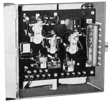
Figure 3-7. Special D.C. Motor Controller. Tapped Tubular Resistor, at right,
is for adjusting motor field currents and presetting motor speed.
8. Performance Data-Accurate resistor performance data is particularly valuable for determining the useful life of a resistor under average as well as adverse application conditions. Such information must often be obtained before final selection of the proper type resistor can be made. Some of the tests that are performed on Vitrohm wire-wound power-type resistors include: momentary overload, heating and cooling, humidity, vibration, mechanical strength, mechanical shock, salt water immersion, thermal shock, salt spray corrosion, insulation resistance and dielectric strength.
The primary purpose of these tests and the basic test procedure used, as well as test results on representative production samples, will be discussed in subsequent paragraphs.
Figure 3-7. Special D.C. Motor Controller. Tapped Tubular Resistor, at right,
is for adjusting motor field currents and presetting motor speed.
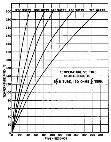
Figure 3-8. Temperature vs Time Characteristic On application of a voltage
to attain 320 watts, the time interval to achieve a maximum temperature rise
( 300°C) is about 3 minutes 35 seconds. Note in the 480, 640, 800 and 1280
watt tests that the time taken to reach a given temperature rise decreases
as the wattage impressed on the tube is raised.
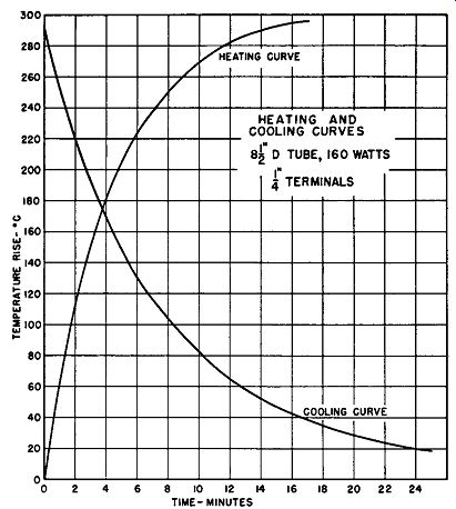
Figure 3-9. Heating and Cooling Curves The heating time required for a resistor
to reach maximum temperature rise depends mainly on:
(1) Wattage dissipated.
( 2) Mass of the unit.
( 3) Its specific heat characteristics.
( 4) The emissivity properties of the materials used.
If a resistor having a thinner core with finer wire embedded in a coating of higher emissivity characteristics were used, the time intervals to attain maximum temperature rise would be lowered accordingly.
Figure 3-9 shows the relationship between the heating and cooling curves for an 8½" D Vitrohm resistor rated at 160 watts. On placing a voltage across the resistor to dissipate full nominal watts (160), the time to reach a temperature rise of 292°C is shown as 17 minutes. Although not shown in Figure 3-9 the heating curve levels off, reaching stabilization (300°C) in about 30 to 45 minutes. Notice that the cooling cycle, i.e., time required for the resistor to reach room temperature is considerably longer than the heating cycle.
--------------- Table 3-2 Humidity Test for Resistors
*Steps 3 to 13 constitute a single 24 hour cycle.
**Followed by vibration test for 15 minutes.
--------------------
When the tube is heating the differential between ambient temperature and resistor temperature becomes greater, whereas during the cooling cycle the differential becomes less, since the cooling medium remains constant.
c. Humidity--Where resistors are used in tropical climates or other excessively humid locations, their ability to withstand high humidity must be determined.
To do this, the resistors are subjected to the temperature and humidity cycles shown in Table 3-2.
Steps 1 and 2 are performed only at the beginning of the test. Step 1 is the initial drying period. The resistance and insulation resistance of the resistors are measured during the last half hour of Step 2 and at the end of Step 9. The resistors are then subjected to the cycling beginning with Step 3.
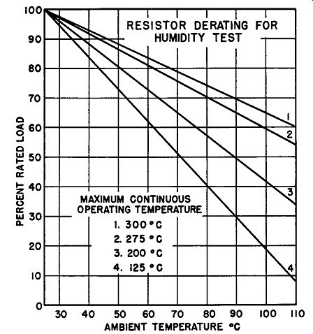
Figure 3-10. Resistor Derating for Humidity Test
During the first two hours of Steps 3 and 6, the rated load is derated to the temperature obtained at the end of the two hour period in accordance with Figure 3-10, and is applied to each resistor from Step 3 through Step 8. During Steps 4, 5, 7 and 8, 100 volts D.C. is applied with positive connected to the resistive conductor and negative connected to the mounting hard ware. During Steps 10, 11, 12 and 13, the resistors are returned to the humidity chamber. Within 15 minutes after the completion of Step 12 the resistors are subjected to a vibration test for 15 minutes.
Test results on typical Vitrohm resistors manufactured specifically for this type service indicate that they are unaffected by this severe test after more than 80 cycles.
d. Vibration - When resistors are mounted in equipment or locations where excessive vibration occurs, they must be constructed so as to avoid damage. In making vibration tests the resistors with their mounting brackets in place are subjected to a simple harmonic motion (amplitude of at least 0.03 inches, total excursion 0.06 inches, frequency varying from 10 to 55 cycles). The 10- to 55-cycle frequency range is traversed every minute for five hours. Then the resistors are checked for change in resistance value and for signs of damage such as cracks, loose parts, etc.
Vitrohm tubular resistors after being subjected to the vibration test show no noticeable signs of cracks or other flaws. Change in resistance value is less than ½ of 1 percent.
e. Mechanical Strength--To make sure that resistors will be able to withstand normal abuse in hand ling, they are tested for mechanical strength. In this test they are supported ¼ inch from each end and a transverse load is applied to the center of the resistor through a beam having a radius of contact of not less that 0.25 inches.
Vitrohm tubular resistors are capable of supporting loads of from 250 to 500 pounds.
f. Mechanical Shock - On portable and mobile equipment, especially in military applications, resistors must be capable of withstanding mechanical shock with out damage to component parts.
In these shock tests, the resistor ( or group of resistors)
is subjected to several blows parallel to the principal axes of the resistance unit or assembly.
The ability of a resistor to withstand shock depends not only on the construction of the resistor but also on the method of mounting used. For example, on ferrule resistors additional clamps must be provided to prevent the resistor from disengaging the fuse clips under mechanical shock. Edison base resistors should be avoided where shockproof construction is desired.
Tubes with short nominal lengths are recommended over those with long nominal lengths.
Vitrohm tubular resistors when equipped with suit able mountings are capable of withstanding numerous blows of from 150 up to 2,000 foot-pounds.
g. Salt Water Immersion--Where resistors are to be used for shipboard and similar applications, they can he furnished with special coatings, and their ability to withstand salt water is determined by the cyclical test.
A single cycle is as follows: Rated power is applied for 2 hours, and the resistance is measured. Within 5 seconds after the removal of potential, the resistor is immersed for 1 hour in a saturated salt-water bath maintained at 100°C -+- 4°C. Within 5 seconds after removal from this bath, the resistor is immersed in another saturated salt-water bath maintained at .0°C ±.g: C for a period of 1 hour. The resistor is then thoroughly and quickly washed in tap water and all surfaces ( external and internal) wiped dry and clean or air blasted. The resistor is then operated at rated power for 2 hours, and the resistance is again measured.
Vitrohm tubular resistors made expressly for this type of service can successfully withstand at least 9 cycles of the above test.
h. Thermal Shock-Because resistors are frequently used in applications where the air temperature varies over wide limits ( for example, airborne equipment) their thermal shock characteristics must be determined.
In thermal shock tests rated, power is applied to the resistor until thermal stability has been reached. The power is then removed and the resistor is immediately subjected to a temperature of -55°C for at least 15 minutes. Then the unit is checked for resistance and is inspected for mechanical defects.
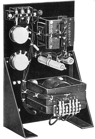
Figure 3-11. Rear View of Hysterset Electronic Lamp Dimmer Control Using Vitrohm
Fixed and Adjustable Resistors.
For applications where the resistors are likely to come in contact with liquids such as water, resistors are some times given another thermal shock test. In this test the heated resistor ( as outlined in the preceding paragraph) is plunged into tap water at 0°C ±.g: C for one minute.
After the above tests Vitrohm resistors show no defects in the embedding coating or other parts that would result in unsatisfactory performance. Change in resistance value is less than ½ of 1 percent.
i. Salt Spray Corrosion--Another test used to determine the ability of resistors to withstand marine conditions is as follows: The resistor is suspended in a closed chamber and subjected to a continuous spray under a pressure of 25 pounds per square inch of a salt solution whose specific gravity is 1.151 at 16°C and whose temperature is 35°C. After being subjected to the above tests, Vitrohm resistors show no noticeable evidence of deterioration after 100 hours. Resistance values change less than ½ of 1 percent from initial values.
j. Insulation Resistance Test--This test is performed on resistors to determine the leakage current from the terminals to the mounting hardware.
In making the insulation resistance test on a resistor ( except ferrule type), the resistance between the resistor terminals connected together and the mounting brackets is measured using a D.C. potential of 100 volts.
The resistance of the insulation of Vitrohm tubular resistors is infinite under standard test conditions.
k. Dielectric Tests--These high voltage tests are performed on resistors to determine the ability of the insulating materials and spacings used to withstand breakdown.
In making dielectric tests on single resistors, except those of the ferrule or axial-terminal type, a high volt- age having a frequency not less than 60 cycles, and approximating a true sine wave, is applied between the resistor terminals and the mounting brackets. The exact voltage applied depends on the voltage rating of the resistor. On resistors designed for use on equipment rated 600 volts and below, an RMS voltage of twice rated volts plus 1,000 volts is applied for at least one minute.
Where the equipment is rated over 600 volts, the dielectric test voltage is 2¼ times the rated voltage plus 2,000 volts.
9. Application Data--When applying embedded wire wound power-type resistors, the following essential characteristics should be known:
(1) Load versus temperature rise ( 2) Grouping and spacing ( 3) Derating factor for enclosures ( 4) Voltage on unit ( 5) Duty on unit
a. Load versus Temperature Rise-The curves of Figure 3-12 show the temperature rise that can be expected at any load from zero to 100 percent of rated load for resistors whose nominal rating is based on a 250°, 300° or 375°C rise as measured under standard test conditions with one foot of free air space around the resistor. The 300°C or the 250°C curves should be applied to Vitrohm units while the 375°C curve is applicable to open or un-embedded resistors such as Ribflex.
If a resistor such as Vitrohm is rated on the basis of a 300°C rise and is subjected to 50 percent of rated load, the curve reveals that the temperature rise will be 195°C. Similarly, if a resistor rated on the basis of a 375°C rise has a temperature rise of 212°C, the curve indicates that the resistor is operating at 40 percent of rated load.
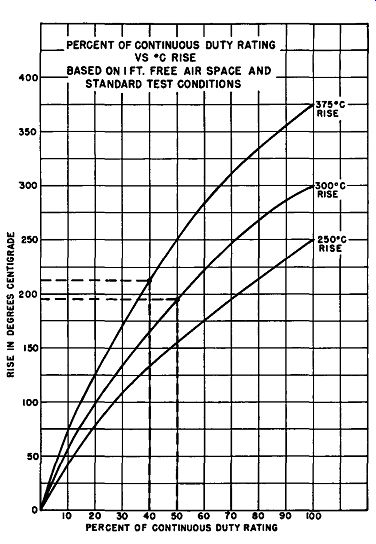
Figure 3-12. Percent of Continuous Duty Rating vs deg. C Rise
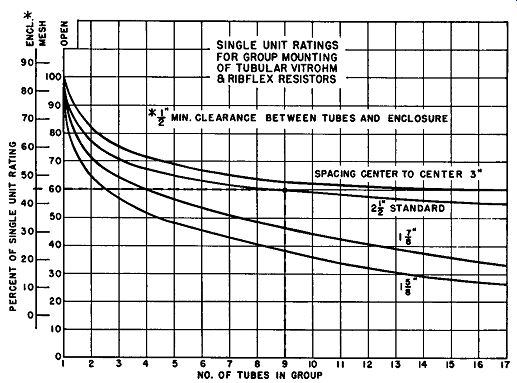
Figure 3-13. Single Unit Ratings for Group Mounting of Tubular Vitrohm and
Ribflex Resistors.
b. Group Mounting--Figure 3-13 shows curves of percent of single unit rating against number of tubes in a group. Separate curves are given for four spacings, and in any group of three or more, the spacing between adjacent tubes is identical. Two percentage scales are shown; one for free air and the other for mesh enclosure. These curves apply to tubular Vitrohm and Ribflex resistors. Note that the rating varies with the spacing.
Example: With nine units in a group mounted in open air using 2½ inch centers, the percentage of single unit rating is 60 percent. Assuming each tube in the group is an 8½" D, rated at 160 watts continuous duty, then the continuous duty rating of the entire group is determined by: Number of tubes in group x Rating of each tube x Percent of single-unit rating = Total continuous duty rating of group.
9 x 160 x .60 = 864 watts
c. Enclosures--Since resistors are seldom mounted in free space and still air, their nominal watt ratings must be reduced to avoid exceeding the maximum allowable temperature rise. For example, resistors are normally mounted either in separate enclosures or with other components tending to restrict ventilation and to cause an increase in temperature rise. In some instances, the temperature of associated components may bring the temperature of the resistor beyond safe limits. In other applications the reverse is true, i.e., other components may be damaged by the temperature of the resistor.
The approximate percentage derating for groups of Vitrohm resistors housed in metal mesh enclosures is shown in Figure 3-13. In the example given previously the total continuous duty rating of the group in free air is 864 watts. If this assembly of resistors is mounted in a metal mesh enclosure, the rating of the group must be reduced by 15 percent. The enclosed rating of the group is equal to 864 x .85 or 734 watts. The curves of Figure 3-14 compare the ratings of an 8½" D Vitrohm resistor when mounted in four different types of metal enclosures.
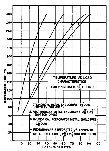
Figure 3-14. Temperature vs Load Characteristics For Enclosed 8½" D Tube.
Figure 3-15. Adjustable tubular resistors, lower right, utilizing vertical through-bolt mounting are an essential component of the Electronic Automatic Alternator Voltage Regulator shown.
d. Maximum Voltage Limitations-Where high resistance values are required, the voltage impressed across the resistor terminals may take precedence over the resistor watt rating. On high-voltage circuits ( 600 volts or above), the voltage between turns of the winding must be kept within specified limits to assure safe operation and to prevent breakdown in service.
Table 3-3 Voltage Limitations.
Table 3-3 lists the maximum recommended voltage rating expressed in RMS volts for Vitrohm tubular resistors of different core lengths. Ratings are based on a value of 495 RMS (700 peak) volts per linear inch of core length. The values shown will always assure safe operation devoid of failures. When high voltages are applied, Vitrohm resistors have withstood several times these values without impaired operation.
As an example of how to use Table 3-3, consider a type 50 F, 176,000-ohm, Vitrohm resistor which is rated at 50 watts and has a nominal core length of 4½ inches.
Computing the voltage across the tube required to dissipate 50 watts by the equation:
E = y R x W
…where E is the voltage drop, R the resistance in ohms and W the watts dissipated we obtain 2970 volts. Table 3-3 shows that the maximum voltage rating for a 4½ inch tube is 2230 volts. Thus, for safe operation, a 6 inch tube with a maximum voltage rating of 2970 volts should he selected.
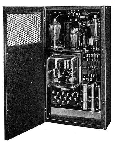
Figure 3-15.1. Vitrohm tubular resistors, at top of Rheostat Motor Drive Assembly, are for speed adjustment purposes.
In applications where extremely high-voltage surges for very short time intervals (milli-seconds) are known to occur surge-wound resistors are available. These resistors have wider spacings between the turns at each end of the tube, thereby increasing the insulation resistance between those turns.
e. Intermittent Duty--Vitrohm resistors are de signed primarily for continuous-duty applications hut there are numerous instances in which they are useful for intermittent-duty service. The curve of Figure 3-28 shows the high intermittent-duty ratings of Vitrohm tubular resistors. Under average conditions, the ratings indicated on the curve will not exceed the maximum permissible temperature rise of 300°C.
B. STRIPOHM RESISTORS. Stripohm resistors, Figure 3-16, are especially useful in those applications where space for components is at a premium.
1. Construction-Except for the fact that Stripohm resistors utilize a flat, oval-shaped, ceramic base on which the resistive conductor is wound, they are practically identical in construction with Vitrohm tubular resistors.
The core or base has a smooth surface with no sharp edges. This design precaution is taken to guard against wire breakage during manufacture. The fact that the core is slightly elliptical in shape, as indicated in Figure 3-16, increases the radiating surface slightly, provides a core considerably stronger than an ordinary flat rectangular base, and insures that the wire lies flat against the entire winding surface.
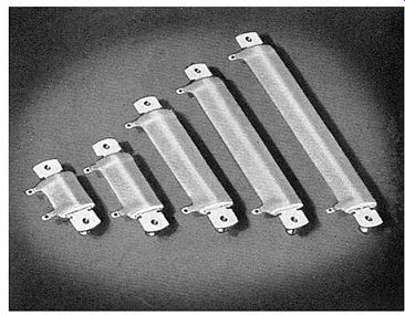
Figure 3-16. Stripohm Fixed Resistors equipped with spring-clip mounting brackets.
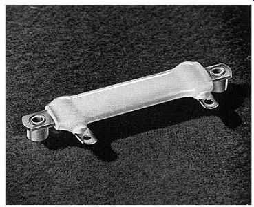
Figure 3-16a. 20 Watt Mini-strip Resistor shown actual size.
Stripohm resistors are equipped with metal strip ( spring clip type) mounting brackets. Where adjust ability is essential, Stripohms can he supplied with a hare side and hand for adjustment of resistance value.
Tapped Stripohm resistors, where more than one step is needed, are also available. On the largest size ( 6 inch) unit, twelve steps can be furnished. Tab terminals are standard for all Stripohms.
2. Methods of Mounting--Several methods of mounting Stripohm resistors are illustrated in Figure 3-17. In all methods the mounting brackets, as mentioned previously, are of the spring-clip type. Figure 3-l 7b is the standard mounting for single Stripohm resistors of all sizes. Figure 3-17 c shows how Strip ohms are stacked using standard brackets. To increase the stacked rating, n inch metal spacers (washers) should be inserted between units. The method used in Figure 3-17a is for mounting single Stripohm resistors where the overall length of the assembly must be minimized. The method shown in Figure 3-17 d, though unsuitable for stacked mounting, is useful where the overall height of a single Stripohm unit must be less than that found on standard brackets.
3. Ratings--Stripohm resistors are made in six standard sizes ranging from 20 to 75 watts. The method of rating strips is slightly different from that of conventional forms of resistors. A strip resistor is mounted horizontally on a vertical flat steel plate, 10 inches square and 0.040 inch thick, using the mounting brackets illustrated in Figure 3-17b. This entire assembly is then mounted in free air. The maximum permissible temperature rise on which the rating is based is 300°C in an ambient temperature not exceeding 40°C. Resistance values range from a minimum possible resistance 0.1 ohm to a maximum possible resistance of 115,000 ohms. Resistance tolerance is the same as that for Vitrohm tubular resistors discussed on Page 47.
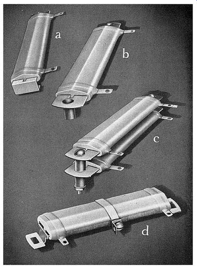
Figure 3-17. Typical Methods of Mounting Stripohm Resistors a-Inverted metal spring clip, b--Standard metal spring clip, c-Stack mounting using standard brackets, d-Metal spring clip.
Figure 3-18. Derating Curves for Stripohm Resistors stacked horizontally and vertically
4. Performance Data--Except for slightly lower resistance to high mechanical shock, Stripohm resistors can meet the same tests as outlined for Vitrohm tubular resistors. The shorter length units should he specified where vibration is excessive and multi-stacked assemblies should he avoided where severe mechanical shock conditions prevail. Salt water immersion tests on Stripohm resistors are based on a maximum allow able temperature rise of 175°C.
5. Application Data - Because Stripohm resistors utilize Vitrohm construction, the application data given on pages 59 to 67 for Vitrohm resistors, except for grouping and spacing information, can he applied to Stripohm units.
a. Group Ratings--Figure 3-18 shows the effect of stacking on the rating of Stripohm resistors. All resistors are equipped with standard spring clip brackets as shown in Figure 3-17b. For example, 55-watt Strip ohm resistors, stacked in groups of two with their faces vertical, are rated at 79% of 55, or 43.4 watts. If stacked with their faces horizontal, the rating is 61.5% of 55, or 33.8 watts.
C. VITROHM NON-INDUCTIVE RESISTORS. Vitrohm fixed resistors of the non-inductive type, Figure 3-19, are designed for high-frequency circuits when power up to 160 watts per unit must he dissipated.
1. Construction--The basic difference in construction between standard and non-inductive Vitrohm tubular resistors is in the method of winding the resistive conductor. In order to lower substantially the inductance and minimize distributed capacitance, non-inductive Vitrohm resistors utilize the Ayrton-Perry method of winding.
The Ayrton-Perry winding consists of two windings in parallel, wound in a single layer in opposite directions.
The turns of the windings cross at fixed points that are at the same potential. In order to insure that the points at which the windings cross are exactly 180° apart, the cylindrical-shaped ceramic core is made with two flat surf aces. This patented method of flat-sided construction further reduces the amount of undesirable inductance. It is vastly superior to the conventional cylindrical non-inductive resistor without flatted sides.
2. Terminals--Vitrohm non-inductive resistors are made with tab or ferrule type terminals illustrated.
3. Mountings--Push-in type mounting brackets are recommended for units equipped with tab terminals.
Ferrule type non-inductive resistors require fuse clips for mounting purposes.
4. Ratings - D.C. wattages of non-inductive tubes range from 10 to 160 watts in 5 standard sizes. Resistance values are available from 1 to 15,000 ohms. Be cause of the method of winding used, the maximum resistance obtainable per unit is lower than with standard Vitrohm resistors.
5. Performance Data-Vitrohm non-inductive resistors can successfully withstand the same performance tests as standard Vitrohm units.
6. Application Data--These data, given for Vitrohm tubular resistors on Pages 59 to 67, apply equally well to Vitrohm non-inductive resistors.
7. Effects of Frequency--The distributed inductance and capacitance of a wire-wound resistor become increasingly important as the frequency rises. Wire size, core size, manner of winding, spacing, etc., all affect the distributed inductance and capacitance.
The curves in Figure 3-20 were made from experimental data taken on several 8½" D, Vitrohm, non inductive resistors, and may be considered representative. In these tests, total reactance was measured and since the capacitive reactance is smaller than the inductive reactance, the total reactance as shown on the curves is inductive.
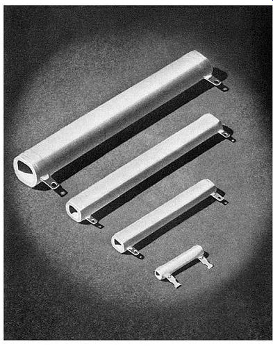
Figure 3-19. Vitrohm Non-Inductive Tubular Resistors
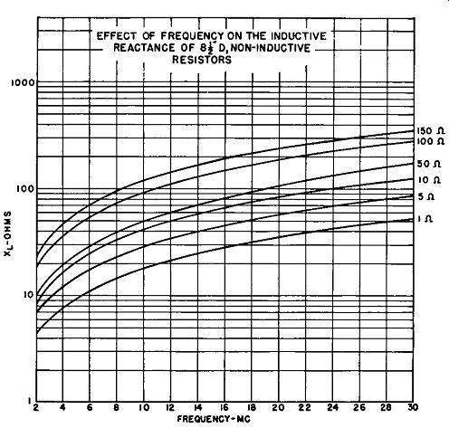
Figure 3-20. Effect of Frequency on the Inductive Reactance of 8½" D,
Non-inductive Resistors
The equation for inductive reactance is:
XL= wL = 2 pi fL
Where f is the frequency and L the inductance.
The equation for capacitive reactance is:
1 1 Xe=-= wC 2 pi fC
Where C is the capacitance. The total reactance is the algebraic sum of XL and Xe.
The schematic diagram of a resistor in a high-frequency circuit is shown in Figure 3-21, where R is the effective resistance, L the distributed inductance, and C the distributed capacitance. The effective resistance is greater than the D.C. resistance due to the high-frequency A.C. "skin effect" in the resistive conductor.
The impedance of the resistor is then equal to the vectorial sum of the effective resistance and the reactance.
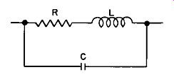
Figure 3-21. Schematic Diagram of a Resistor in a High-frequency Circuit
D. PLAQOHM RESISTORS. Vitrohm Plaqohm Resistors, Figure 3-22, are another popular form of non-inductive resistor, suitable for numerous applications in radio and electronic circuits where a combination of power and high frequencies exists. These flat-type resistors are particularly useful in equipment where space for components is extremely limited.
1. Construction--As shown in Figure 3-22, the plaques in which the resistance wire or ribbon is placed are made of molded refractory ceramics, rectangular in shape. One side of the base contains molded slots for holding the resistive conductor in place and for pro viding proper spacing and insulation between turns.
Copper terminals are silver brazed to the ends of the resistive conductor. The entire assembly, that is, the base, winding and terminal joints, is then coated with a fused-on vitreous enamel. The complete assembly forms a solid homogeneous mass, without air pockets, to provide for the rapid conduction of heat from the resistive conductor to the surfaces of both sides of the resistor.
All Plaqohm resistors use the bifilar method of winding to give low values of inductance. This method is quite different from that used on Vitrohm tubular non inductive resistors. Instead of being wound around the base, the winding is flat and zigzags in the slots in the base. Since each segment of the winding is adjacent to another segment in which the current flows in the opposite direction, the flux linkages cancel, reducing the total inductance. In addition, because there is small potential difference between alternate adjacent ends of the segments and the distance between each segment is relatively large, the distributed capacitance is held to a minimum.
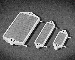
Figure 3-22. Plaqohm Non-Inductive Resistors
Standard Plaqohm resistors are made with two tab terminals. On the smallest size Plaqohm an additional slot is provided in each base for a third terminal when required. Larger size Plaqohms can be supplied with three extra terminals for applications where four resistance steps are required in a single Plaqohm.
2. Mountings--Typical methods of mounting these resistors are illustrated in Figure 3-23. When two Plaqohms are stacked Figure 3-23a, they should face in the same direction and not be placed back to back. This precaution should be observed to allow sufficient electrical clearance between terminals of adjacent units.
Where more than two resistors are stacked, four L-shaped mounting brackets should be used for proper support.
--------------
Mounted on steel panel using metal or ceramic spacers C Mounted on heat resistant insulating panel Figure 3-23. Methods of Mounting Plaqohm Resistors a-Vertical L-shaped bracket mounting, b-Horizontal mounting with spacers, c-Horizontal contact mounting
-------------
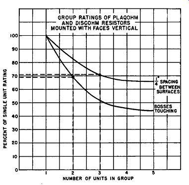
Figure 3-24. Group Ratings of Plaqohm Resistors and Discohm Resistors mounted
with their faces vertical
When vertical space for components is limited, mountings shown in Figure 3-23h and c may be used. If two or more Plaqohms are to be grouped, horizontal mounting is not recommended. When mounting the resistors on a metal surface ( steel panel) as in Figure 3-23b, the vitreous enamel side of the plaque should face away from the mounting panel surface. Spacers must be used to provide adequate clearance between resistor terminals and the panel. Contact mounting, shown in Figure 3-23c, should be used only when the mounting panel is made of an insulating, heat resistant material.
3. Ratings--Plaqohm resistors are made in three standard sizes, rated at 25, 50 and 150 watts. Individual ratings are based on a maximum temperature rise of 300°C in free air. Resistance values range from 0.5 ohm minimum to 86,400 ohms maximum.
4. Performance Data--The test results given previously for Vitrohm tubular resistors apply, in general, to Plaqohm resistors. The molded ceramic base employed is not quite as strong as the extruded tubular ceramic cores found in Vitrohm tubular units. For this reason the large size Plaqohms, or multi-stacked assemblies, are usually not recommended. Where severe vibration or high mechanical shock is encountered, the shorter length units can be used satisfactorily.
5. Application Data--For load versus temperature rise characteristics and derating factors for enclosures, the data given for Vitrohm tubular resistors, Page 59 can be used.
a. A.C. Characteristics--Because of the method of winding, the inductance at frequencies up to 5 megacycles is negligible. Plaqohms are essentially free from standing waves at all frequencies up to 60 megacycles.
A single Plaqohm mounted four inches away from any object and not in the magnetic or electrostatic field of other devices, maintains its resistance value without major variations resulting from frequency changes. This condition prevails at frequencies up to 7, 3 and 0.2 megacycles for the 25, 50 and 150 watt units respectively.
b. Group Ratings--Curves of Figure 3-24 may be used to determine free-air ratings for groups of Plaq ohm resistors mounted vertically. For example, three 50-watt Plaqohm resistors with ¼ inch spacing between adjacent surfaces will have their ratings reduced approximately 29 percent, or to 3 x 50 x . 71 = 106.5 watts.
If two 150-watt Plaqohm resistors are touching each other, that is, mounted side by side without spacing, the rating is reduced 31 percent, or to 2 x 150 x .69 = 207 watts.
When the resistors are stacked with their faces horizontal, the group ratings given in the above examples should be further decreased by 10 percent. Other reductions are necessary when individual or groups of Plaqohms are enclosed.
E. DISCOHM RESISTORS. Another type of non-inductive resistor, known as Discohm, Figure 3-25, is recommended for low-power applications where panel space must be conserved.
1. Construction--Discohm resistor construction follows very closely that of the Plaqohm resistors, except that the winding is laid out radially. The terminals are silver brazed to the resistive conductor and the entire assembly is protected by Vitrohm enamel. Unlike Plaqohm units, Discohm resistors are unavailable with extra taps for additional steps.
2. Methods of Mounting--Discohm resistors are normally mounted by means of metal bolts passing through the countersunk hole in the molded refractory ceramic base as shown in Figure 3-26a. L-shaped brackets Figure 3-26b are sometimes used for mounting 1, 2 or 3 units. The method used in Figure 3-26c combines a through-bolt with two L-shaped metal brackets. The metal spacers are used to increase the single-unit watt rating.
3. Ratings--The free-air rating of Discohms based on a 300°C rise is 24 watts. For higher power applications, two or more Discohms must be stacked together. The use of multiple-stacked assemblies is often advantageous where multi-tapped or multi-section units are needed.
Resistance values range from 1 to 5760 ohms per disc.
The curve given in Figure 3-24 for Plaqohm resistors can be used as a guide for derating groups of Discohms-- since their characteristics are similar. Refer to Page 81 for application and performance data.
Figure 3-25. Discohm Resistors
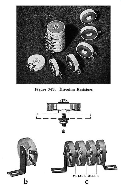
Figure 3-26. Methods of Mounting Discohm Resistors a-Flush mounting, b--L-Shaped
brackets, c-Through-bolt with L-Shaped brackets.
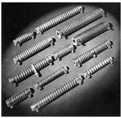
Figure 3-27. Ribflex Resistors
F. RIBFLEX RESISTORS. Rihflex ribbon-wound resistors are designed for intermittent-duty applications, where high wattages must he dissipated by relatively small size resistors, and for continuous-duty resistors, where low resistance values are needed.
1. Construction--Ribflex resistors, Figure 3-27, consist essentially of crimped resistance ribbon wound on edge on a refractory ceramic tube, and silver brazed at each end to heavy, screw-type terminals. Vitreous enamel is applied to the surface to anchor the ribbon and terminals securely in place.
Rihflex construction offers several advantages over conventional forms of tubular flat-wound, ribbon resistors. First, the crimped ribbon affords a greater surface area for heat dissipation compared with units using flat-wound ribbon or wire. Second, because Rib flex resistors are classified as bare resistors, the maximum permissible temperature rise is 375°C. The increased temperature rise gives higher wattages for a given size.
Third, since the resistance ribbon and terminals are permanently secured to the ceramic tube, Rihflex units are more adaptable than hare-type resistors to applications where mechanical shock and vibration are encountered.
2. Terminals--Heavy-weight, screw-type terminals are considered standard for Rihflex resistors. For applications where two or more steps are required per tube, terminal taps can he provided. The maximum allowable number of taps per tube depends on the nominal length of the resistor and on the resistance required per step.
Adjustable band-type terminals, similar to those used on Adjustohm resistors, can he used where adjustability is needed.
3. Mountings - All the methods of mounting described for Vitrohm fixed resistors are applicable to Ribflex units. Through-bolt type mounting brackets are recommended for mounting two or more Ribflex resistors.
4. Ratings-Continuous duty ratings for Ribflex resistors range from 75 to 600 watts maximum. Standard resistance values are from 0.04 ohm minimum to 66 ohms maximum, per tube.
The standard resistance tolerance for Ribflex units from 0.5 to 66 ohms is +- 10%. For values below 0.5 ohm and on tapped units the tolerance is +- 15%. Ribflex resistors with tolerances as low as ½ of 1 percent are available at increased cost.
5. Performance Data--Although Ribflex resistors are classified as open- or bare-type resistors, they success fully meet many of the tests described on Pages 48 to 59 for Vitrohm tubular resistors. For example, Ribflex units withstand the same momentary overload, mechanical strength, mechanical shock and thermal shock tests performed on Vitrohm units. The heating and cooling curves for Ribflex are also similar to those given on Pages 50 and 51. Because the resistive element is exposed, "wet" tests such as salt spray, humidity and salt immersion are not as favorable as for embedded types. In the case of the salt spray immersion, for example, the number of hours Rihflex units withstand this test depends mainly on the resistance alloy used.
However, specially designed Rihflex units have been manufactured specifically for marine service.
6. Application Data--When using Ribflex resistors, data given for Vitrohm tubular resistors, including load versus temperature rise, grouping and spacing, and de rating for enclosures are applicable.
7. Intermittent-duty Ratings - Intermittent-duty ratings for Ribflex and other resistors are based on their continuous-duty rating and then modified according to the duty cycle. The curve in Figure 3-28 gives the relationship between the percent of single unit watt ratings of resistors at various intermittent duty cycles. The values shown are with 2½ inch spacings and a maximum temperature rise of 375°C. To apply this curve, let us assume that in a motor starter for a D.C. motor driving a constant speed compressor, the duty cycle is to he 10 seconds "on" out of each 80 seconds and that the power to be dissipated in starting is 13,000 watts (RMS). From Figure 3-28 it can he seen that the rating for the specified duty cycle is 475 percent or 4.75 times the continuous duty rating.
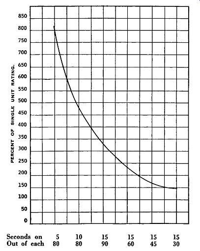
Figure 3-28. Effect of Intermittent-duty Operation on Rated Capacity of Vitrohm
and Ribflex Resistors.
Referring to Table 3-4, we find that twelve 11 ¾" D tubes will be required if the resistor assembly is mounted in free air. Table 3-4 compensates only for derating the tubes when grouped, using 2½ inch centers.
For mounting on 1 5/8", 1 7/8" or 3" centers use curve Figure 3-13.
Table 3-4 Continuous-Duty Ratings of Grouped Ribflex Resistors*
Mounted on 2½" centers
* Assembled group suspended in still air at least one foot from nearest object.
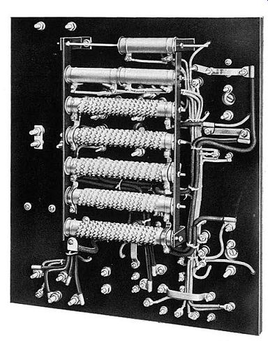
Figure 3-29. Rear view of D.C. motor starter. Ribflex resistors, lower section,
are for starting purposes. Vitrohm tubular resistors, upper section, are for
control circuit purposes.
In practice, further derating is required to compensate for increased temperature rise when the tubes are mounted in an enclosure or in locations where ventilation is restricted. This ordinarily means increasing the size or number of tubes in the group. No specific calculations can be given that will apply to all applications since conditions vary so widely. However, the safest procedure is first to estimate the rating of the group based on the above example. Then add sufficient units to the group to compensate for lack of ventilation, other spacings, etc. Finally, run temperature rise tests under conditions simulating those in the actual application.
G. EDGEOHM RESISTORS.
Industrial demands for high-current resistors, lighter in weight and sturdier in construction than cast iron grid resistors, prompted development of Edgeohm resistors. Another vital factor influencing the original design was the need for high-current resistors that could be used economically in both intermittent- and continuous-duty applications.
1. Construction--A typical Edgeohm high-current resistor is shown in Figure 3-30. The resistive conductor consists of a single piece of non-corrosive resistance ribbon wound on edge to form oval-shaped coils. This continuous ribbon element is mounted on grooved ceramic saddles that space adjacent turns and insulate the resistive conductor from the supporting metal bars.
End pieces of steel are utilized to space the supporting bars. For external connection to each end of the resistive conductor clamp-type terminals are provided. Where taps are required along the resistive conductor additional clamp-type terminals are readily attached.
2. Mountings--There are two standard methods of mounting Edgeohm resistors. For single units stamped steel mounting brackets, Figure 3-31a, are recommended.
These brackets assure maximum cooling and convection efficiency since the resistor is mounted with the long axes of the unit and the oval coils in the same horizontal plane. Stamped steel brackets are equally suited for mounting on metal or insulated panels.
The second standard method of mounting Edgeohm resistors is by means of steel mounting frames shown in Figure 3-3lb and c. These frames accommodate from one to three units in a single frame and may be stacked in one or more vertical tiers.
In both types of mounting, secondary insulation is provided between the resistor assembly and the steel mounting brackets. This additional precaution affords double insulation between the ribbon element and ground, primary insulation being furnished by the ceramic saddles of the Edgeohm resistor.
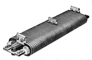
Figure 3-30. Edgeohm Resistor without Mounting Frames or Brackets
3. Ratings--Because Edgeohm resistors utilize un-embedded or bare resistive elements, free-air rating for a single unit is based on a maximum temperature rise of 375°C. Edgeohm resistors are made in five standard lengths, 5½ inches to 19 inches maximum. The continuous-duty rating of the 19 inch Edgeohm resistor is 2,200 watts.
Variations in resistance and current capacity are obtained by changes in alloy, size ( cross-sectional area) and length of the ribbon. The standard range of resistance values is from 0.05 to 4.40 ohms, while the continuous current rating is from 79 to 21 amperes. Resistance tolerance on all units is + 20 - 10%.
4. Performance Data-Edgeohm resistors, like Rib flex tubular units, meet many of the tests that are made on embedded power resistors. When equipped with suit able mountings, Edgehom units, singly or in multi-deck assemblies, withstand an exceptionally high degree of mechanical shock. Standard units meet the requirements for railway and other mobile equipments. Edgeohm resistors, after being subjected to more than 100 hours in the salt spray corrosion test, show no visible damage from the effects of corrosion and, electrically, no measurable change in resistance values occurs.
Figure 3-31a. Typical Methods of Mounting Edgeohm Resistors a-Stamped steel brackets-single unit mounting, b---Steel mounting frames.
Figure 3-31b. Typical Methods of Mounting Edgeohm Resistors; c-Multi-unit mounting using steel mounting frames.
Figure 3-32. Edgeohm Resistor Intermittent-duty Ratings.
5. Application Data--The same general precautions as already described for Ribflex resistors should be taken when applying Edgeohm resistors. Reductions in free-air ratings should be made for grouping two or more units, enclosures, etc.
6. Intermittent-duty Ratings--The effect of intermit tent-duty operation on the ratings of an Edgeohm resistor are shown in Figure 3-32. Ratings given are based on a 375°C rise in free air.
If 8,800 watts (RMS) must be dissipated during a duty cycle of 10 seconds "on" out of each 80 seconds, Figure 3-32 indicates that the percent of continuous duty rating is approximately 400 percent, or 4 times the continuous-duty rating. Selecting Edgeohm resistors rated at 2,200 watts continuous duty, we note that one resistor will be needed, as determined by the following equation:
Number of resistors required = Intermittent-duty watts (RMS) Continuous-duty rating X percent or continuous-duty rating 8,800
Number of resistors required = ---- = 1 2,200 X 4
7. Group Ratings--Table 3-5 can be used as a guide in determining the continuous-duty ratings of Edgeohm resistors when group mounted. In horizontal stacking the long axes of the unit and of the ribbon coil are horizontal. The vertical centerline-to-centerline dimension is 5 inches and units are mounted one above the other. In vertical stacking the long axis of the coil is vertical and units are mounted one above the other with 6½ inch centerline-to-centerline spacing.
Table 3-5 Group Ratings of Edgeohm Resistors ---- PERCENT OF SINGLE UNIT RATING* ----- *Continuous-duty ratings based on a maximum temperature rise of 375°C in 40°C ambient air. Units are mounted in free air.
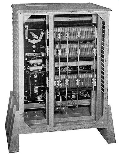
Figure 3-33. Rear view of D.C. motor controller. The Edgeohm starting resistors,
at right, are mounted with long axis of coil vertical to conserve space.
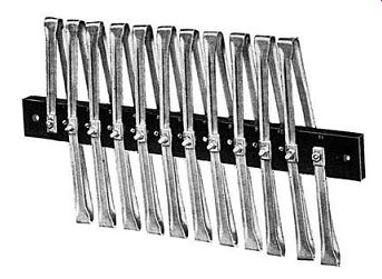
Figure 3-34. Typical Barohm Resistor
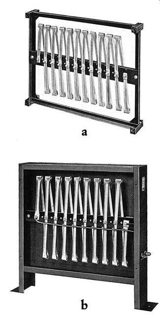
Figure 3-35. Typical Methods of Mounting Barohm Resistors a--Open type metal
frame, b--Enclosed frame for floor mounting-front cover removed.
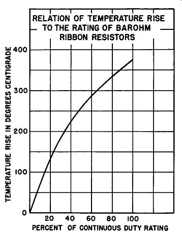
Figure 3-36. Percent of Continuous-duty Rating versus Temperature Rise of
Barohm Resistors
H. BAROHM RESISTORS.
Barohm resistors are designed for high-current applications requiring a low-cost, light-weight, continuous duty resistor.
1. Construction--A Barohm resistor, as illustrated in Figure 3-34, consists of a channel-shaped alloy resistance ribbon, of uniform cross section, formed in a series of flat turns secured at the middle of their short axes to specially treated asbestos cement composition support bar. The ends of the support bar are provided with mounting holes. External connections to the resistive conductor are made by means of two stud-type terminals, Figure 3-35h. Additional taps on the resistive elements can he furnished on the support hoard, or clamp-type terminals can he supplied for connection along the ribbon.
Although the support bars are made in lengths from 6 to 30 inches, the 23 inch length is considered standard.
To meet varying height requirements, standard heights of 16, 20 and 24 inches are available.
2. Mountings--Barohm resistors may be mounted in open, or enclosed, formed steel frames as shown in Figure 3-35a and b. Notice that the long axis of the ribbon is vertical. Enclosed frames are suitable for floor mounting while the open-type frames are suitable for mounting directly on panels or switchboards. The open-type frame is useful for applications requiring multi-unit assemblies. For the larger resistance banks, it is common practice to mount individual units in a specially built angle iron frame either open or enclosed, with perforated or expanded metal mesh instead of solid, sheet steel panels. The metal mesh protective enclosure is preferred because it allows adequate ventilation.
3. Ratings--The continuous-duty ratings of Barohm resistors are based on a 375°C temperature rise for a single unit mounted in free air with the long axis of the resistive ribbon vertical. Continuous-duty current capacities range from 340 amperes maximum to 18 amperes minimum.
Resistance values are obtainable from 0.15 to 7 ohms maximum on standard units. Factors that determine resistance limitations include: length of ribbon that can be placed in the allotted space, size of ribbon used and resistance alloy selected. Standard resistance tolerance is + 20 -10%.
4. Performance Data--Barohm resistors are generally unsuited for application where high mechanical shock, humidity or salt spray is encountered. The impregnated asbestos support for the alloy resistance ribbon is considerably weaker mechanically than the ceramic saddle, steel support base utilized on Edgeohm resistors. however, for ordinary commercial and industrial applications Barohm units prove entirely satisfactory and, in general, are the most economical form of high-current resistor for continuous-duty service.
5. Application Data--The curve in Figure 3-36 illustrates the effect of load versus temperature rise on Bar-ohm resistors. Ratings given represent average values of typical size units mounted in open-type frames like the one in Figure 3-35a. Where two or three units, each mounted in open-type frames, are stacked side by side, the nominal rating of each unit should be reduced by about 10 percent. On multi-unit assemblies containing four or more Barohms, each mounted on open-type frames, the nominal rating of each unit should be reduced hy 15 percent. Further reductions in these free air ratings must be made for operation in ambients higher than 40°C, in enclosures, etc.
To illustrate the use of the curve shown in Figure 3-36, assume a single Barohm resistor, rated at 100 amperes and having a resistance of 0.31 ohms, carries a load of 50 amperes. The temperature rise of the resistor can he estimated as follows:
Watts dissipated = FR = 502 X 0.31 = 775 watts P f
. d 775 2~01 percent of cont duty watts = 3100
= "10
Referring to the curve in figure 3-36, the 25 percent of continuous duty rating will give a temperature rise of approximately 150°C.
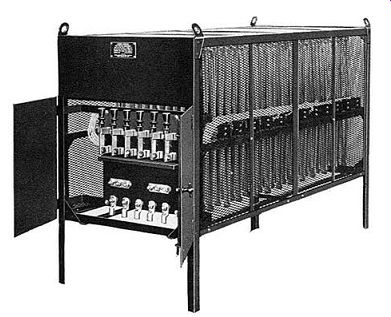
Figure 3-37. The 100 K.W. Loading Rheostat illustrated above utilizes Barohm
ribbon-type high-current resistors.
One of the primary applications of Barohm resistors is for load banks like the one shown in Figure 3-37.
Other typical continuous duty applications include: battery charging resistors and rheostats, projection arc rheostats, space heaters and ballast resistors. For high current intermittent duty uses Barohm resistors are generally unsuited and Edgeohm or groups of Ribflex resi11tors should be applied.
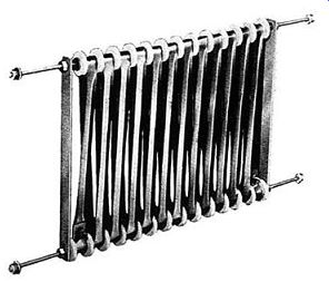
Figure 3-38. Loopohm Resistor without End Frames or Brackets I. LOOPOHM RESISTORS.
Loopohm resistors, Figure 3-38 are recommended for high-current, continuous-duty applications where mechanical shock and vibration prevail.
1. Construction--The Loopohm resistor is essentially a variation of the Barohm resistor previously described.
It consists of a channel-shaped alloy resistance ribbon of uniform cross section formed in a series of loops sup ported between two rods insulated with ceramic bushings and washers. The horizontal rods are spaced and rigidly secured by means of vertical steel support bars.
Each unit is equipped with two end terminals for external connections. Additional taps for intermediate resistance values can be had as shown in Figure 3-39.
Clamp-type terminals mounted along the ribbon can be used where adjustability is required.
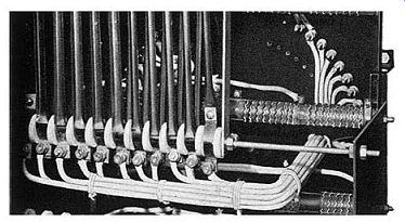
Figure 3-39. Special multi-tapped Loopohm Resistors are shown in foreground.
2. Mountings--For mounting in control equipment the open-type resistor Figure 3-40a is recommended.
For external mounting, singly or in multiples, standard end frames Figures 3-40b and c should be used. Units using end frames have secondary insulation between the two horizontal rods and the end mounting frames, pro viding double insulation to ground. Loopohm units are also obtainable with expanded or sheet metal enclosures.
3. Ratings--Loopohm resistor ratings compare favor ably with those for Barohm resistors. The height of Loopohm resistors is standardized at 15 inches while the overall length can be 18½ inches or 23½ inches. These fixed overall dimensions place certain limitations on the range of resistance and current values that can be sup plied with Loopohm. Continuous current ratings of standard units range from 110 to 20 amperes. Usual resistance values are from 0.14 to 6 ohms per unit while the standard resistance tolerance is + 20 - 10%.
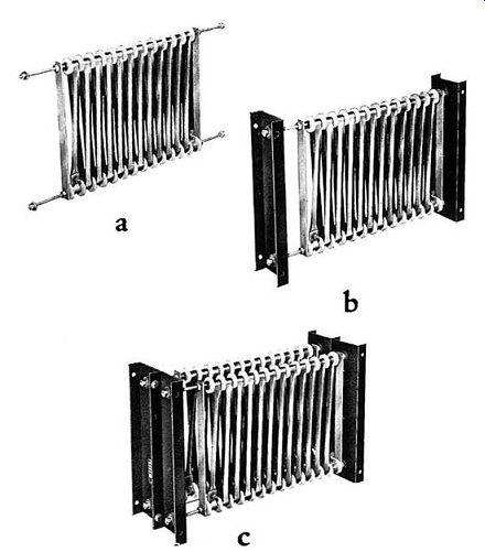
Figure 3-40. Typical Methods of Mounting Loopohm Resistors a-Open mounting
without end frames, b-Open mounting with end frames, c; Multi-deck mounting
with end frames.
4. Performance Data-Loopohm resistors have practically the same performance characteristics as Edge ohm units under continuous-duty service. Because the alloy ribbon resistive conductor is supported at both ends, Loopohm units are recommended for use in port able and mobile apparatus that is subjected to severe mechanical shock or excessive vibration.
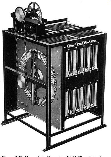
Figure 3-41. Heavy-duty Generator Field Rheostat using Loopohm Resistors
5. Application Data-Refer to Barohm application data, Page 98.
J. SPECIAL TYPES OF RESISTORS.
All the power resistors discussed previously are considered standard units, both from the standpoint of design and of the manufacturing processes involved.
Besides these types which are ordinarily stocked by the manufacturer in a wide variety of sizes and ratings, there are limitless others that may be considered special types. Many of these special type resistors are so classified because of their limited use in commercial and industrial equipment. Others are considered special types due to their unusual or non-standard construction.
Four of the more important special types include: channel, sandbox, coiled wire and Ribohm resistors.
a. Channel-type Resistors.
Channel-type resistors, Figure 3-42, are actually a variation of Ward Leonard Vitrohm pressed steel rheostats. They are made by placing the resistive conductor in an insulated metal pan with a fused-on vitreous enamel.
Connections to the resistor are made by tab or screw type terminals. Each end of the metal pan has extended ears for mounting purposes.
Sizes of channel resistors are from 2 x 4 inches to 5¼ x 9 3/8 inches with watt ratings from 90 to 350 watts respectively, based on a temperature rise of 300°C. Although channel-type resistors are higher in cost than tubular or strip resistors, they have the advantage of being available with a large number of steps. Steps can be tapered or arranged to meet design requirements.
Their high mechanical strength makes them particularly suited for shockproof installations.
Channel resistors are generally applied in voltage and speed regulating equipment, or in conjunction with tap switches to give various resistance values.
Photo courtesy of Burlington Instrument Co.
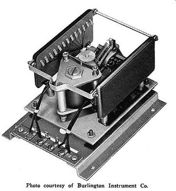
Figure 3-42. Multi-tapped Channel-type resistors on the A.C. Rheostatic Direct
Acting Voltage Regulator shown, furnish the resistance for automatically adjusting
exciter field currents and for dropping the voltage to the solenoid coil.
b. Sandbox Resistors.
Sandbox resistors, Figure 3-43, are sometimes used where high wattages are encountered for extremely short periods of time. These resistors are made of heavy, coiled, alloy wire or crimped ribbon that is fastened to one side of an impregnated asbestos board insulating base. This assembly is placed in a metal box, usually cast iron, and the box is tightly packed with fine quartz sand.
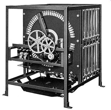
Figure 3-43. Large Sandbox Resistor for field discharge purposes shown in
lower front section of Motor Driven Field Rheostat
Since the sand is in direct contact with the entire resistive element, the unit has high heat-absorptive characteristics, increasing the short-time thermal capacity of the resistor and preventing high wattages from damaging the resistive conductor.
Dimensions of sandbox units range from 7 x 8½ x 4 inches to 15½ x 18 x 4 inches. Usual resistance values ...
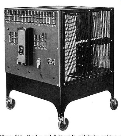
Figure 3-44. Barohm and light-weight coiled-wire resistors
are used in the Ward Leonard 30 K.W. portable loading rheostat shown.
... are from 0.2 to 25 ohms per unit. Ratings of sandbox resistors are for intermittent duty only, and are based on the constants of the circuits in which they are used.
Sandbox resistors are generally used for field discharge and dynamic braking purposes.
c. Coiled-wire Resistors.
These resistors are used where a low-cost, extremely light-weight resistor is required.
In one method of construction, the coiled resistive conductor is stretched between insulating supports, and connections are made at the support points. Another variation consists of a coiled resistance wire that is wound around a flat, treated, asbestos board. External connections are made to terminals provided at each end of the board or base.
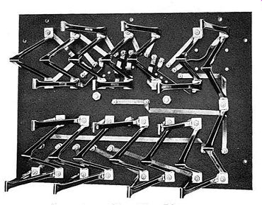
Figure 3-45. Rear view of Face Plate Rheostat using Ribohm Resistors
Coiled-wire resistors are applied primarily for continuous-duty purposes such as in load hanks, Figure 3-44.
Since these resistors have relatively low heat-absorptive characteristics, they are generally unsuitable for intermittent-duty service.
d. Ribohm Resistors.
Ribohm, a fourth special type resistor, is a variation of the Barohm ribbon resistor. As shown in Figure 3-45, the alloy ribbon resistive conductor is formed into a shallow channel shape for stiffness and then formed into a vee, the ribbon being flat where the bends occur.
The ends of the vee-shaped unit are also flat, and punched for securing to the terminal studs.
Ratings of Ribohm resistors, like all un-embedded units, are based on a temperature rise of 375°C. Continuous-duty ratings range from 15 to several hundred amperes. The large size units are sometimes applied in high-capacity load hanks, or used for face-plate type rheostats. Smaller units are often used as shunts, connected across the series field of a D.C. motor or generator.