These complex components are seldom properly understood even by those who specify them.
by Gordon Hulyer
[Gordon Hulyer is quality assurance manager at Cathodeon Crystals in Linton. Cambridge. He is active on both British and international standards committees for piezoelectric devices.]
==========
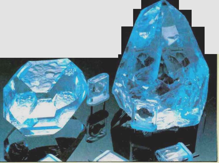
above: Raw material and finished product-a group of glass holder quartz
crystals.
There are two aspects of quartz crystals used as frequency controllers which are opposite yet equally valid. One is that they are essentially simple components with only two terminals; that simplicity has ensured their continued and expanding use since they were first used for radio more than 40 years ago. The other is that they are complex components, seldom properly understood even by those who specify them for use in electronic circuits.
It is this second aspect that this article seeks to expound in the interests of users, because failure to specify the correct type of unit for a specific task can result in unnecessary cost as well as failure in performance. For example, it pays to be very specific about the temperature range within which the unit will operate. Failure to do so may result in a crystal exhibiting unwelcome errors in service.
Furthermore, the most important development of quartz crystals in recent years has been the improvement in long-term stability or ageing properties, as a result of improved cleaning and encapsulation techniques, so it is important to make the right choice in relation to this, among many other parameters.
Because quartz crystals are piezoelectric devices, relying on mechanical motion to generate electrical properties, they are susceptible to mechanical as well as electrical problems. Thus stiction (static friction) manifests itself, in electrical terms, as a variation in crystal impedance with drive level; and as with mechanical stiction, the impedance characteristic has hysteresis. For this reason, it is extremely difficult to specify a quartz crystal in such a way that it will operate reliably in an unspecified semiconductor circuit particularly a circuit designed for low power consumption, as this is usually associated with a situation where the crystal is being driven at a low drive level, i.e. in the region of maximum stiction.
The crystal
Need for care in specifying crystal units arises from the methods employed to manufacture them.
In fact a specification will effectively determine how the unit is or has been made, and with the now widespread use of integrated circuits instead of discrete components it has become even more important to exercise care.
Each crystal unit is cut from the mother crystal at a precise angle in relation to the crystallographic axis; this angle usually the "AT angle" is chosen in relation to Young's modulus of the material, the piezoelectric coupling, and the acoustic velocity, in such a way as to produce a crystal which, in its performance, will be as nearly independent of temperature as possible. After cutting, the crystals are individually sorted into several grades, and then all are lapped to within a half light-band of flatness. Electrodes subsequently deposited on the opposite faces of the crystal serve not only as electrical contacts but also finalize the frequency of the unit: by precise, automatic deposition of the thin gold or silver electrode the physical mass of the unit can be adjusted to give the desired frequency.
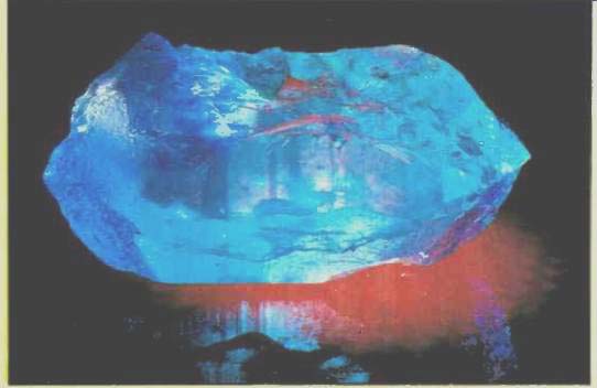
--- Pretty, but seldom used nowadays in the manufacture of crystal
units, except in very low frequency applications: yield is much higher with
synthetic quartz.
The required operating temperature range and frequency tolerance will therefore determine how the crystal plate is cut in relation to the crystallographic axis of the raw material. Its geometric shape and diameter are determined by the parameters L, C1, R, and Co amongst others (see section headed "Parameters"). The crystal electrode material, its method of deposition, and mass are all determined by what is specified by the user. In the event of a particular parameter not being specified, it will almost certainly mean that the unit supplied may not necessarily be the one needed. It will have been made by one of the manufacturer's standard methods, which may or may not match the user's requirements.
Holders
Crystal holders are of four types, and are universally known by their names: solder seal, resistance weld, cold weld, and glass.
Solder-seal holders, the least expensive, suffer from poor long-term ageing performance as it is impossible during manufacture to completely eliminate the flux residue. Also it is extremely difficult to achieve the low level of leaks required for good long-term performance. They should therefore be considered only when there is nothing of equivalent dimensions available in one of the other types.
Resistance-weld holders are currently the most popular form of encapsulation. They are a distinct improvement on solder seal holders, but they require local heating during the welding operation and are therefore not as reliable as cold-weld or glass holders. Except where ultra-high long-term stability is required, resistance-weld holders can be used for all applications. Typical uses are for microprocessors, data communication modems, paging systems, mobile and portable radio, and military communications. The resistance weld method gives a good clean construction at relatively low cost.
Cold-weld holders are more expensive, but they give an improvement in long-term ageing compared with resistance-weld units, and a significant improvement over solder seal. The encapsulation is achieved by heatless welding of the can and base a very high pressure being applied over a localized area to cause the two surfaces (usually copper) to flow together to form a homogeneous bond.
The process is carried out in a vacuum or in nitrogen. There is thus neither flux residue nor local heating of any significance. The two surfaces, however, must be free of contamination and oxidation, and this is usually ensured by depositing a thin layer of nickel place on each surface so that the nickel ruptures during sealing.
For applications similar to those for resistance-weld holders, cold-weld holders may therefore be preferred if price' constraint is not a major factor.
Glass holders are 'a must' for applications where ageing is of paramount importance. The base and envelope are sealed together by radio-frequency heat melting the two surfaces so that they fuse together. By means of a ring of Kovar (a nickel-iron alloy having the same coefficient of expansion as glass), the heat is concentrated in the contact area, and the whole process is carried out under vacuum after de-gassing at about 500°C to remove any organic matter. The main applications for glass holders are frequency standards, satellite navigation, measuring instruments, microwave beacons, and synthesizers.
Parameters
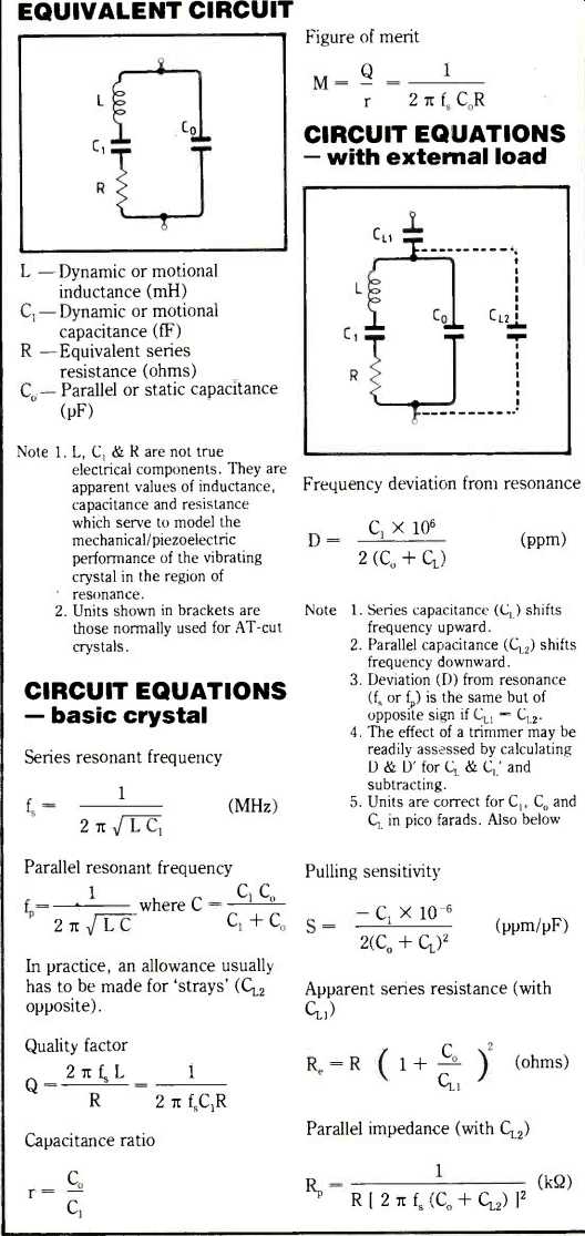
There are at least ten parameters affecting the choice of a quartz crystal unit. The properties of a quartz crystal can be represented by an equivalent circuit consisting of an inductor L, capacitance C1, resistance R, shunted by a second capacitance Co, as shown on page 54. Capacitance CL is an external load capacitance specified, if required, by the user.
These four parameters are constant and independent of frequency and amplitude changes, providing the crystal unit is operated in the correct way. The parameters L, C1 and R are termed the "motional parameters" of the unit; f_s is the series mode, f_P the parallel mode.
A manufacturer or supplier needs to know, in addition to the nominal operating frequency, the following, which significantly affect the design criteria:
---frequency accuracy (calibration or adjustment tolerance)
---frequency stability with temperature
---frequency stability with time (aging).
These first three parameters constitute the 'accuracy' of the crystal. They should be selected with care as unnecessary over-specifying only serves to make the crystal more expensive. Typical values for the four types of holder are given in Table 1. Other important parameters are
- operating temperature range
- maximum resonant resistance (e.s.r.) (R)
- motional inductance L or motional capacitance C1
- parallel capacitance Co
- power dissipation (drive level)
- unwanted responses
- holder style
- load capacitance (CL)
- environmental factors.
The choice of holder is determined mainly by (1) the long-term stability required, (2) environmental factors, (3) operating frequency (blank diameter), and (4) the price the user is prepared to pay. If the crystal is to be used in a potentially hostile environment, e.g. guided missile and satellite applications, it is important to consult the manufacturer as a ruggedized mounting can be chosen to suit the particular application.
Applications
Table 2 gives typical application in order of cost, starting with the most expensive, set against certain general parameters and other features.
From a manufacturing point of view, the lower unit costs are associated with the larger volumes of production. It is not practicable to correlate the four types of holders directly with this list, though the glass holders would normally only be used for the upper group of applications and some of the second group. It is advisable to consider resistance-weld holders for all other applications.
Whenever conditions permit it is always advisable to discuss your application with the manufacturer; experience in other areas could be extremely beneficial when considering your particular needs.
Crystal oscillators
It is possible to produce R C or L C oscillators which have a stability of 0.1% under ideal conditions, but this is unlikely to be sufficient if the "Rule of 10" is followed, i.e. over-specify to a factor of 10, or even 100, to be sure of the required reliability and integrity.
Thus a desired accuracy of 0.1% becomes ideally a requirement for a frequency source with an accuracy of 0.001%, or 10ppm.
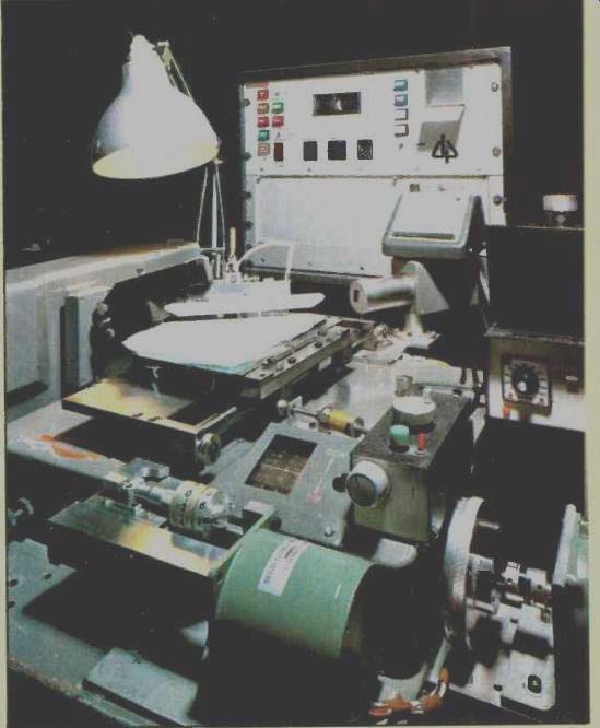
above: Setting accuracies of ±0.1 minutes of arc prior to cutting
are needed in positioning quartz to achieve the required performance.
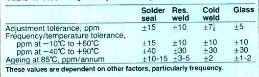
Table 1. ‘Accuracy' of crystals comprises three parameters
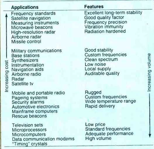
Table 2. Quartz crystal applications against features
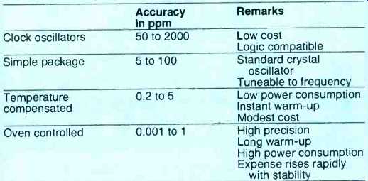
Table 3. Stability of four main types of crystal oscillator. The clock oscillator
is the basic crystal oscillator. A distinction is drawn between simple-package
and clock oscillators, as clock oscillators often do not incorporate any means
of frequency adjustment.
Even the simplest of crystal oscillators will achieve an overall accuracy of 100ppm for all reasons (setting accuracy, temperature, ageing, etc.). Such devices therefore provide a cost-effective solution to the less stringent electronic requirements.
These "clock oscillators" are available in various outlines to suit situations where either height or area (as on p.c.b’s ) is limited. A survey of models commercially available has shown that they have accuracies in the range 50 to 1000 ppm (0.005 to 0.1%). For more demanding applications, crystal oscillators which are temperature compensated or oven controlled are recommended. Table 3 shows the stability of the four main types of crystal oscillator.
Simple packaged oscillators (SPXO) are the least complex. Some have a remote frequency control capability, i.e. they incorporate a variable capacitance diode in the frequency circuitry, and are called voltage-controlled crystal oscillators (VCXO). They are more susceptible, in frequency control, to variations in power supply voltage, but the user can add extra voltage immunity. Temperature-compensated oscillators (TCXO) are characterized by a temperature dependent reactance in the frequency control loop, designed to compensate for variations of frequency with temperature. They are expensive because the reactance has to be synthesized to make it complementary to the cubic-shaped dependence of the AT-cut crystal, and this has to be optimized for each crystal.
Oven-compensated oscillators (OCXO) achieve stabilities of 1pp 10^10 per day be means of extremely precise temperature control using a built-in double oven and vacuum flask, together with careful circuit design. These crystal oscillators are used as "secondary standards". For most applications, however, a single oven design is adequate, giving stabilities of 0.1ppm in respect of temperature variations.
The physical dimensions of the space available for the crystal oscillator may also have a bearing on the choice. The height or area may be restricted; in either case there will be a specific unit which is suitable.
Thick amorphous metals
Amorphous metal alloys can have interesting properties, such as hardness combined with ductility, magnetic softness and very high corrosion resistance.
Until recently they could only be produced in strips of less than 0.05mm thick but much thicker nickel-titanium and nickel-zirconium compounds have now been produced using a technique known as rapid diffusion.
To create amorphous metals, extremely rapid cooling from the molten state is required to ensure that a crystalline structure has no time to form during solidification. Current techniques involve spraying the melt onto a cooled rotating copper drum but to achieve a sufficiently high cooling rate the resulting layers must not be more than 0.05mm thick. Rapid diffusion, however, has been used to produce strips of up to 1mm thick and even tubes.
This new technique involves rolling together alternate, 25µm-thick layers of nickel and zirconium. Subsequent annealing for around 150 hours at between 300 and 350°C causes the nickel atoms to diffuse into the zirconium layers. At these temperatures, the zirconium atoms are practically immobile and an amorphous structure stable up to about 500°C is formed.
===============
What is a quartz crystal?
A quartz crystal is cut from a bar of manufactured quartz. It is cut very precisely in relation to the crystallographic axis of the crystal and is formed into a thin disc, rather like an optical lens. Two electrodes are secured to it, one on each side, by vacuum deposition of silver, gold or aluminum.
When a voltage is applied to the electrodes the crystal changes its shape due to its piezoelectric properties, thus causing a stress to be applied to the crystal. If this stress is varied by reversing the applied voltage, the crystal will be subjected to an alternating stress and will tend to vibrate at its natural frequency. Thus resonance is initiated. The frequency of resonance is so precise with quartz crystals that they can serve as frequency determining devices, and they are considerably more precise than a tuning fork because of the high purity of the quartz material.
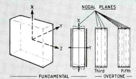
A quartz crystal may operate in its fundamental mode generally up to 30MHz or at the third, fifth, etc., overtones, as shown below. The mode of vibration is in thickness shear, so the critical dimension controlling the frequency is in "Y", i.e. the thickness of the plate.
The vibrations are shown extending to the edge of the plate, but in practice the plate is designed to confine the vibrations to the centre, in the area of the exciting electrodes.
Strictly speaking, this unit is a resonator. When it has been encapsulated in one of several possible ways it then becomes what is generally known as a "quartz crystal". If the quartz crystal is then built into a appropriate electronic circuit it becomes a quartz crystal oscillator, i.e. a complete frequency controlling system.
Relevant crystal theory is summarized on page 54. For those who wish to study the relevant standards, refer to British Standard 5069, for standard outline and pin connections of quartz crystal units, and to those listed on page 54.
==========
-----------
CRYSTAL THEORY, EQUIVALENT CIRCUIT, etc.
----------
Further reading
Virgil E. Bottom. Introduction to Quartz Crystal Unit Design. Van Nostrand. 1982.
Marvin E. Frerking. Crystal Oscillator Design and Temperature Compensation. Van Nostrand, 1970.
Benjamin Parzen: Design of Crystal and other Harmonic Oscillators. Wiley, 1983.
Ballato. A. Resonance in Piezoelectric Vibrators, Proc IEEE vol. 5. Jan 1970, pp.150-151.
Holbeche & Allen: The Influence of Series Reactance on Quartz Crystal Resonators. Proc IEE vol. 130, part G no.4, August 1983, pp.145-152
International standards
IEC 122: Quartz crystal units for frequency control and selection.
IEC 122-1 (1976): Standard values and test conditions.
IEC 122-2 (1969): Guide to the use of quartz oscillator crystals.
IEC 283 (1968): Methods for the measurement of frequency and equivalent resistance of unwanted resonances of filter crystal units.
IEC 302 (1969): Standard definitions and methods of measurement of piezoelectric vibrators operating over the frequency range up to 30 MHz.
IEC 444 (1973): Basic method for the measurement of resonance frequency and equivalent series resistance of quartz crystal units by zero phase technique in a pi-network.
IEC-444-2 (1980): Phase offset method for measurement of motional capacitance of quartz crystal units.
BS 9610 (1982): Quartz crystal units of assessed quality: generic data and methods of test.
(adapted from: Wireless World , Apr. 1985)
Also see:
Stereo Phono Cartridges-- A review of the various types of transducer available [late 1969]