by J.J. Wiseman
Efficiency and radiation resistance of electrically short transmitting antennas especially of the inverted-L kind leave a lot to be desired.
The International Maritime Organization is presently rearranging maritime radio with greater emphasis on use of 2182kHz for distress and inter-ship working. There will be a temptation to use only whips. At 2182kHz they will have a small radiation resistance, under 1 ohm, and the current problem of 500kHz short-wire aerials having this kind of radiation resistance, swamped by leakage losses in rough weather, will then be repeated. Nothing will have been gained by the change over...
------------
------------
Technical literature on transmitting antennas, as found in libraries and bookstores or published in popular journals, seems to fall into two categories. The subject is either presented as page after page of complex mathematics, written by PhDs to be read by other PhDs, or it comes as a cookbook or catechism, which everybody 'knows' by heart but few really understand in-depth but find convenient for every day practical use. Thus "A quarter-wave vertical has 50ohm feed, a half-wave dipole 74 ohms, end-fed half waves have 600ohm line" and there are similar psalms to be sung for Yagis, rhombics and other exotica. As all have a radiation resistance far greater than any likely losses, they all work without problems and with good and predictable efficiency. Amen and praise the mathematicians, who made it all possible and put it in a book of revelations. When multiband specials are described, their design often contains more 'art' than science, and performance is assessed subjectively. They are usually justified in terms of s.w.r., which doesn't necessarily say everything about efficiency as a radiator.
People to whom 'bigger' usually means 'better' have become accustomed to seeing very satisfactory mobile communications carried out with antennas less than a meter in length (at v.h.f/u.h.f.), and some have come to believe that 'short' is good enough at any frequency, and it is the layman the coat-hanger bender more often than not who puts up the money and 'does it himself'. In h.f. mobile applications, land vehicles, small boats (and even large boats), the whip or short wire antenna will be all that is possible, yet may be required to operate over a wide frequency spectrum. Accurate information on performance is hard to find.
All that the ARRL Antenna Book has to say is that "Information about the radiation resistance of antennas of less than quarter wavelength is difficult to come by" and leaves it at that. This is the `no mans land' of aerials.
Antennas of less than lambda/4 are not supposed to exist, but at very low and low frequencies they cannot really be avoided; it is hardly possible to erect lambda/4 1500-meter vertical for a 50kHz military transmitter. It is in this area that the performance of the electrically short antenna has been most thoroughly studied; the enormous cost in engineering structures involved has made it essential. Such antennas may have to operate with radiation resistance of only 0.05-ohm. The subject had been well covered by the 1930s but was published not in books, rather in Proceedings of I.R.E., and similar, and therefore inaccessible to the general reader.
The experience is transferrable to other short antennas.
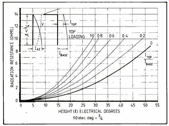
Radiation resistance is plotted against actual antenna height in the graph below in degrees (lambda/4 = 90 degr). Various 'rules of thumb' exist for computing radiation resistance for short antennas.
The 1930 Admiralty Handbook of Wireless Telegraphy, offers the rule RT= 160 pi^2 h^2/lambda^2 = 1580h^2/ lambda^2 and Martin and Carter of RCA Laboratories, N.Y., (1961) repeat the same equation. 'h' is the effective height of the antenna, equal to actual height (l) when base current is equal to top current. For any other current distribution, effective height is that of a rectangle having equal base and equal in area to that under the curve of current distribution. Laport gives RT=10Go^2 where Go is the electrical height of the antenna in radians and transforms this into R1 = 0.1215A^2 where A is the degree-ampere area of the plot of current distribution. In any event, the curve of RT: 1 is a parabola, or a family of parabolas. For Rr = 1-ohm, aerial height (without top loading) has to be about 18 electrical degrees, or with top loading, giving linear current distribution, 9 degrees.
Compare this with RT for a lamba/1 grounded vertical: 36.57ohms according to Everitt, who provides the full mathematical derivation. This RT will be "the same for an antenna 2.5 meters high at 30MHz, 250 meters high at 300kHz or 777 miles high at 60Hz". Similar considerations will apply for antennas of less height. How fortunate were the early aviators who could reel out their trailing aerial to any convenient lambda/4!
A '22-foot' whip is a popular antenna for small water craft. It can be required to operate in marine R/T bands, at, or close to 2, 4, 6, 8, 12, 16 and 22MHz. The 22ft whip has a physical length of 6.7 meters, lambda/4 at 11.19MHz (neglecting 'and effect'), near lambda/4 at 12MHz, 3 lambda/8 at 16 and lambda/2 at 22MHz. But at 2MHz it is only 0.045k, and at 6MHz only 0.13 of a wavelength.
At these frequencies it is "electrically short." Table 1 reveals the shift in performance.
Losses will occur by inductive heating of material of the whip and any adjacent metal, and in the earth connection. Low-loss connection to the water may be difficult to achieve with a wood or glass fiber hull. Assuming lumped losses of 1, 3 and 5 ohms then
efficiency = RT/[ RT + Rloss] X 100%.
Efficiency is given in Table 2 for a 22ft whip, Tables 3 & 4 give equivalent data for a 12 ft whip.
When the whip is operating at less than lambda/4 it is capacitive. Parallel leakage at the base insulator can be converted to series equivalent resistance
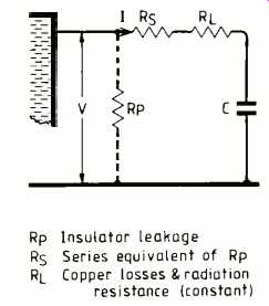
For equivalence, power absorbed in Rp must equal power absorbed in R5:
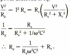
As RS is very small compared to Rp, last term can be neglected, giving
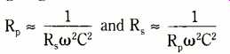
series equivalent leakage being inversely proportional to f^2 & C^2. If C = 40pF, f = 2MHz, and Rp = 1M ohm, then RS is about 4 ohms, about doubling or trebling the existing lumped losses. If this halves Q, then Iae is also halved, and so is Zr, resonant input impedance of parallel circuit formed by the whip and its associated tuning inductance. If the coupling can't cope, the reduced load offered to the p.a. valve or transistor reduces its efficiency as a generator, further reducing Iae.
With a wire antenna, given the voltage distribution highest at the far end, then leakage at the far end will have worse effect than the same leakage at the feed point
(Zr = E/CR_S).
Merchant ship antennas
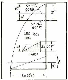
Forty meters of wire bent into an L, with a 15 meter vertical portion is not untypical. This length is better than lambda/4, at 2MHz (vertical portion 36 degrees, Rr > 16 ohms and low L/C ratio), better than one wavelength at 8MHz or higher; radiation resistance is 30ohms or more in any h.f. band, and h.f. efficiency is high under any conditions. At 500kHz, the vertical portion has an actual height of 9 electrical degrees, the remaining 15 degrees (25 meters) being 'top loading'. According to the commercial designers, the top loading does not radiate; it is called the 'suppressed portion'. They concentrate attention on radiation from the vertical portion to achieve a desired field strength at a given distance, and include any radiation from the top and its associated radiation resistance in the 'losses'. A well designed symmetrical top with equal currents flowing in opposite directions might not radiate much at all (e.g. T-antenna), but an inverted-L is going to radiate two components, that from the vertical section being the most predictable and most useful.
The full 40 meters of wire (24°) in the inverted-L has a potential radiation resistance of about 1.9ohms at 500kHz, (not necessarily fully realised). As shown right, the current distribution in the vertical portion is, for practical purposes, a trapezium of the dimensions indicated
Area
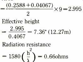
Looking at it another way, the trapezium is equivalent in area to a triangle of equal base and height 1, so that 0.4067xl/2=2.995, so that 1 = 14.73° (24.55 meters). So the top loading effectively increases actual antenna height, as far as the vertical portion is concerned, from 9 to 14.73°. An antenna of this height without top loading also has RT= 0.66ohms, as can be verified from the curves on page 24.
If a 400-watt transmitter puts 10 amps up such an aerial, the power radiated from the vertical portion, omnidirectional and vertically polarized, will be 66 watts, and best efficiency about 16.5%. If leakage causes Iae to fall to 1 amp, then power radiated drops to 0.66 watts, and transmitter antenna efficiency down to a miserable 0.165%! Current in the capacitive branch of a parallel resonant circuit (the aerial) = Ic= QI. Introduction of 20 ohm series resistance, equivalent to 20 ohm parallel leakage, would decimate the Q, and the loss of resonant impedance Zr that goes with it adds loss of p.a. generator efficiency, or simply trips the overload. At the same time it is difficult to ignore the fact that at 10 amp base current, current at the 'bend' is 10 x 0.2588/0.4067 = 6.4A. The top is 15° in length, Rr at least 0.68ohm, and power radiated from the top = (6.4)^2 X 0.68 = 28W, most of it fired off in the direction of other planets, and not to other ships. Total power radiated is 23.5%, 16.5 usefully.
When radiation from the flat top exceeds that from the vertical portion, a limit is reached.
Perhaps an inverted-L is not a very good investment. The optimum top loading for this antenna would be about 81° non radiating, producing a rectangular pattern of current distribution in the 9° vertical and accepting more current at less potential. Area of current distribution is then 9, and a triangle on the same base has height 18°, Rr about 1 ohm. Further increase in Rr would require an increase in vertical height beyond the present 9°. Optimum top loading doubles the effective height and quadruples radiation resistance (Rr for a simple 9° aerial is 0.25 ohm). Even then, to maintain a radiated 10 watts, 3.2A aerial current is required.
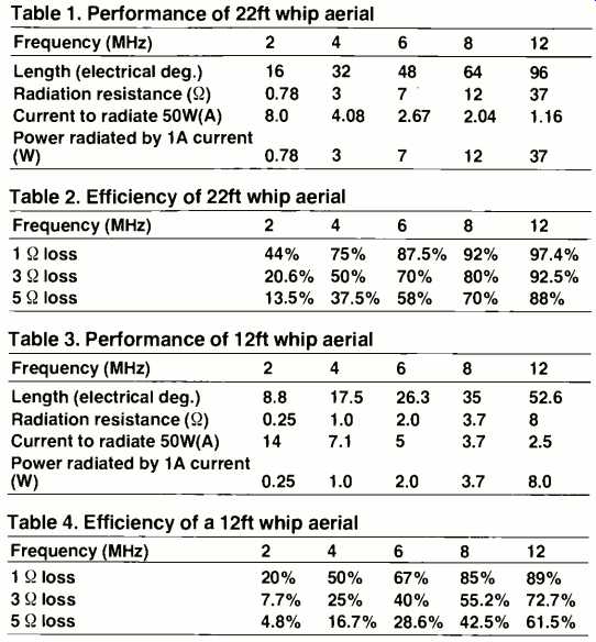
Table 1. Performance of 22ft whip aerial
Table 2. Efficiency of 22ft whip aerial
Table 3. Performance of 12ft whip aerial
Table 4. Efficiency of a 12ft whip aerial
Bibliography:
Cutting, F. Simple method of calculating radiation resistance. Proc. IRE April 1922.
Everitt, W.L. Communication Engineering. McGraw, 1937
Jasik, H. (ed) Antenna Engineering Handbook. McGraw Hill, 1961
Laport, E.A. Radio Antenna Engineering, McGraw Hill, 1952
Lindenblad & Brown, Main considerations in Antenna Design Proc. IRE Jun 1926
Brown, W.W. Radio frequency tests on antenna insulators Proc.IRE Oct 1923
Wiseman, J.J. Anybody seen our ship? Nautical Review May 1979
Ballantyne, S. Radiation resistance of simple vertical antenna at wavelengths below the fundamental Proc. IRE Dec 1924.
Smith & Johnson, Performance of short antennas. Proc. IRE Oct 1947.
==========
(adapted from: Wireless World , Apr. 1985)