Subcode converter for CD
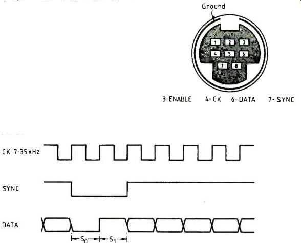
Serial subcode data from a Pioneer PD6010 disc player is converted by this interface into twelve bytes for feeding into a microprocessor.
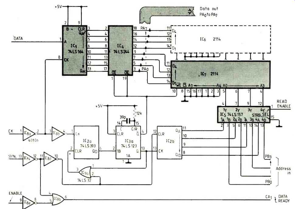
Data from the player is shifted into an LS164 register using the player's clock signal which also increments input-bit counter IC2a. When eight bits have been shifted the bit-counter's D output goes high.
This triggers the LS123 monostable multivibrator, causing parallel data from the shift register to be written into ram. At the same time, the write pulse clears the bit counter and increments ram-address counter IC2b.
When a sync pulse is sent by the player, both counters are cleared and a DATA READY signal is produced. The falling edge of this signal interrupts the microprocessor connected to the interface. Signals ENABLE and SYNC from the player are gated together to inhibit DATA READY when incoming subcode data is invalid.
In response to the interrupt, the processor gains access to the ram address lines by taking the multiplexer select input high so that the 12 bytes can be read. Data must be read within 1.3ms of the falling edge of DATA READY since the interface generates a write pulse for the next subcode block after this time. Reading can still take place after the DATA READY signal returns high.
In a 6502-based computer with a 6422 v.i.a., the CBI input can be used to sense the DATA READY interrupt. Data format is described in Watkinson's article 'Subcodes explained' in E&WW, September 1986.
----------------------
One IC PWM power amplifier
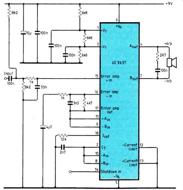
In this pulse-width-modulated amplifier intended for voice-grade communications receivers, a UC3637 switched-mode control IC functions as a class AD audio power amplifier.
Bandwidth is 300Hz to 2kHz, voltage gain is around 10 and maximum input voltage is about 1V pk-pk. These quantities are impossible to measure directly because audio output is available only as sound from the loudspeaker. Electrical output from the amplifier is a pulse waveform which the loudspeaker filters to form the audio signal.
The amplifier operates in an open loop configuration with output switching frequency set to 30kHz. Closed-loop operation is possible but the switching frequency must be increased to the point where switching losses become excessive. Without feedback, the 3637's pulse-width modulator is very linear.
A small 8-ohm loudspeaker can be driven at adequate volume levels but for safe continuous operation, the amplifier should drive a load resistance of at least 30 ohm.
Addition of a four-transistor H-bridge driver would increase output capability.
Supply current is 145mA during normal operation with a 30 ohmload. Taking the shutdown input high, to about 7V or higher, or letting if float reduces supply current to 29mA. A low-pass filter at the amplifier input is designed for 600 ohm. If this value is different, adjust the value of the 1kOhm resistor connected to pin 15 so that the sum of this resistor and the output resistance is about 1.6141.
The entire amplifier, including the loudspeaker, should be shielded to prevent radiated RFI.
-----------------------
Call-cost calculator
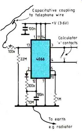
If you have meter pulses on your telephone line, a cheap pocket calculator and simple circuit can be used to monitor call costs without making physical contact with the telephone line.
To put the meter pulses on your line, BT will charge about £17 and a £2.50 a quarter rental charge thereafter. The pulses are easily distinguished from other line currents since they are high-amplitude signals fed down both wires of the line in parallel and earth referenced.
All that's needed to detect the pulses is a capacitive pick-up device consisting of a dozen turns of wire wrapped around the telephone line (or a medium-sized Bulldog clip). Earth connection can be made to a nearby radiator or pipe of any sort.
The circuit is based on a quad analogue-gate and can be made small enough to fit inside a pocket calculator. It is powered from the calculator batteries and draws very little current in standby mode.
Functionally the circuit consists of a high-impedance buffer followed by a rectifier and smoothing network to reject short-duration interference. The final stage cleans up the pulse and provides a switch output.
Output connections are wired in parallel with the calculator keypad "=" key. The calculator should have an auto-constant facility, as most do. Try to obtain a calculator without automatic shut-off, otherwise the setting-up procedure will have to be carried out each time a call is made.
Before making a call, press the clear key, enter the unit cost (currently 5.75p), press the plus key twice, then press the equal key.
Check counting by pressing the equal key, then press zero. Each time a pulse is received, the calculator adds the unit cost to the displayed total. The total can be left to accumulate or be zeroed before each call is made.
Making connections on some types of calculator keyboards may prove difficult, though a combination of screws, conductive paint and solder will cope with most types.
---------------------------
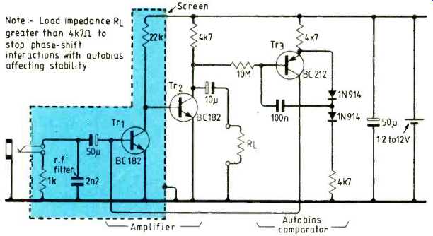
Auto-biasing preamplifier
Resistor-based auto biasing circuits do not work well with low supply voltages. This general-purpose preamplifier uses active auto biasing and runs with supplies from 1.2 to at least 12V, taking about 0.5mA from a 2.4V supply.
Active auto biasing uses a transistor to compare mean output level with a reference voltage and feed back corrections even at low supply voltages. In most low-noise preamplifiers, VcE is kept small to minimize shot noise. Here, the first transistor is kept almost saturated and the collector of the second is at mid-rail for maximum output-voltage swing.
Low-frequency roll-off is determined by the low-pass filter used to average output level and high-frequency performance depends on transistor characteristics. With the input open-circuit, the filter must give sufficient attenuation near d.c. to make the auto biasing stable.
Input-signal impedance should be less than about 1kfl, and amplitude a few millivolts, so the amplifier is suitable for coil microphones and tape heads. In the prototype, Tr1,2 had gains of about 500 and Tr3 about 190.
------------------------------------
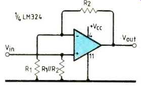
Half-wave rectifier
A basic LM324 non-inverting amplifier working from a single-rail supply can be considered as a precision half-wave rectifier.
Note that the peak negative value of Vin must not exceed 300mV. For higher voltage, add a series resistor at the input to form a potential divider. A coupling capacitor may be used if necessary.
----------------------------------
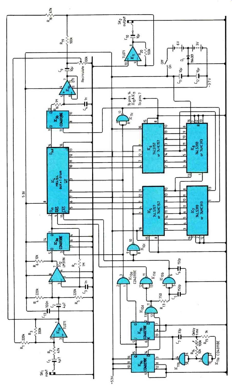
Compact digital echo unit
Despite its simplicity, this compact sound-delay unit gives a repeating echo with a half-second period and good fidelity. Input and output are at line level and current consumption is about 65mA. Two controls are provided; the delay-time control gives the period between echoes and the recirculate control sets the fraction of the delayed signal fed back to give multiple echoes. The unit's single 64K-bit ram IC gives a comparable memory to echo units with eight-bit converters and 8K-byte of storage.
Simplicity is achieved through use of a type of digital/analogue conversion known as delta-sigma modulation. As well as requiring few components, this type of converter produces only one output bit and so does not suffer from the same kind of clipping distortion that occurs when conventional converters are overdriven. Instead, over-large signals cause slew-rate distortion which is far less noticeable to the ear. This means that far less headroom needs to be allowed for sound peaks when setting up and the overall signal-to-noise ratio is correspondingly increased.
Each memory location is selected in turn; on each selection, old contents are read and new data is written. Time taken to cycle round all 65536 locations is the echo or delay time.
Counter IC9 is constantly clocked at around 500kHz by the oscillator formed by IC11a,b. This counter is used as a sequencer to control the rest of the digital electronics. It counts through four phases 00, 10, 01 and 11, performing the following actions.
In phase 00, ICI1, goes low, incrementing the main address counter IC7,8. During the rest of this state, the address counter ripples through and settles down.
During phase 10, IC11d pulls the memory its line low. This causes the memory to latch the low eight bits of the address counter and takes care of memory refresh. At about 3Ons after RAs, the signal propagates through the delay section around IC10b. This causes data selectors IC5,6 to switch and present the high-order eight bits of data to the memory.
At the same time, CAS is pulled low.
Phase 01 causes the memory device to recall its stored information for the current address and put it on pin 14. This data is latched into IC3b on the transition to the next state.
The memory's WE line is held low during phase 11, causing data from IC3a to overwrite the data that has just been read out. At the end of the state, CAS, RAS and WE all go high and IC3a is clocked to fetch a new bit from the input.
I have built the unit into an existing commercial mixing desk between the echo-send and echo-return connections. It is wired so that it switches out when an external effects unit is plugged in. However the circuit can be used as a stand-alone unit without modification.
Using battery power only a single-pole on/off switch is needed. When the circuit is switched off, the diode prevents power drain from the -3V battery.
---------------------------------
==========
(adapted from: Wireless World , Dec. 1986)