by FRANK A. REGIER
It should be possible to produce full-wave rectification using only a single diode--if only by accident.
The student of Fourier series is often surprised to find that a full-rectified sine wave differs from a half-rectified wave of twice the amplitude only in the presence of absence or a fundamental --frequency sine wave. The panel shows the half-wave-rectifier has the form of et, and the full-wave rectified wave has the form of e3, from which it is clear that e3 can be formed from et by the addition of the sine wave e2 =-E0 sin wt. These waves are shown in Fig.1, and it can be seen either from the Fourier series or from direct inspection of the waveforms that e3=e1+e2. This relation suggests that it should be possible to build a full-wave rectifier utilizing this principle of voltage addition and having only one diode.
A naive application of this idea results in the circuit of Fig.2. This circuit will clearly not operate as intended because the two transformer voltages are simply added and their sum rectified, resulting in the voltage e5 of Fig.3. Since e5=e4 and e, must be as shown in Fig.1, e4 must have the form shown in Fig.3.
The difficulty with the circuit of Fig.2 is that the voltage e4, which was intended to have the form el, is allowed to go negative.
The obvious cure is a clamping diode, resulting in the circuit Fig.4. This circuit does indeed produce the desired output e3 but does not of course qualify as a full-wave rectifier with only one diode.
Fig.4 can be simplified and put in more familiar form if it is recognized that the potential at the bottom of the lower winding is the same as that at the centre of the upper winding. The lower winding can accordingly be replaced by a centre tap on the upper winding. The result is the circuit of Fig.5, which is of course simply a conventional full-wave rectifier.
Although we have not yet succeeded in forming a one-diode full-wave rectifier based on the addition of voltages e1 and e2, it doesn't follow that it can't be done. If the half-wave rectifier part of Fig.2 is given a resistive load and no current is drawn from the combined circuit, the voltage e4 will not go negative, and the output will have the desired form e3.
More generally, either circuit of Fig.6 will produce the output voltage e6 shown in Fig.7, and this approaches the desired form e3 if RL is much greater than R I . The circuit of Fig.6(b) is occasionally produced by accident when one diode in a conventional full-wave rectifier fails.
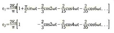
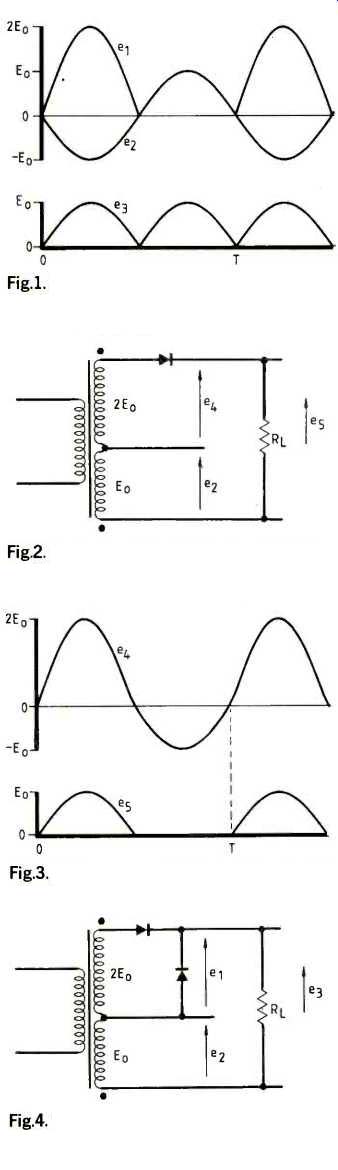
Fig. 1. Full-wave rectified wave e3 is formed by the addition of half-wave
rectified wave el and sine wave e2.
Fig. 2. Unsuccessful attempt at a full-wave rectifier with one diode. Eo and 2Eo are the peak voltages of the two windings.
Fig. 3. Voltages e4 and e5 occurring in the circuit of Fig. 2; e2 is shown in Fig.1.
Fig. 4. The circuit of Fig.2 modified by the addition of a clamping diode produce the desired full-wave rectified output e3.
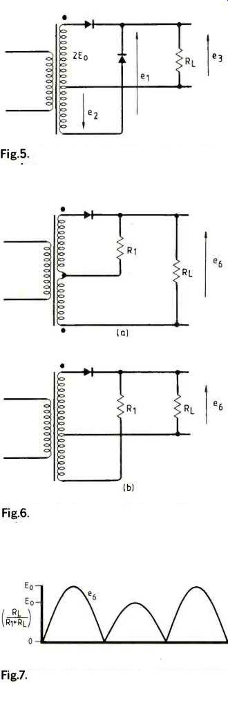
Fig. 5. Conventional full-wave rectifier, equivalent to and desired from the
circuit of Fig.4.
Fig. 6. Equivalent one-diode rectifier circuits using two (a) and one (b) transformer secondary windings and producing the output voltage waveform e6 shown in Fig.7.
Fig. 7. The output voltage e6 produced by the circuit of Fig.6 approaches the desired form e3 if RL is much greater than R1.
==========
(adapted from: Wireless World , Dec. 1986)