by JOULES WATT
RMS is another expression often used without much thought. JW roots out the true meaning.
What is your RMS music power? During very quiet passages, perhaps in the silence just before a dramatic chord--nothing at all! So do such ideas have any meaning, or are they figments of advertisers' imaginations?
ROOT MEAN SQUARE--OR AVERAGES?
The woolly thinking does not end with amplifiers. I came across a student a short time ago, who was quite convinced that the RMS voltage reading produced by his train of square waves on the AVO meter a.c. range bore some resemblance to the truth. A quick look at an oscilloscope showing the same square waves indicated how very far out he was. It took quite a while for him to find why he had an 11% error!
Therefore, are the meter manufacturers conning us for some reason, regarding their RMS a.c. ranges? The answer is no --not if you keep strictly to sine waves, because by a bit of juggling of the meter calibration, an average has been used to denote an RMS value. You can see at once that in no way could you estimate a music RMS value on such a meter.
The simple sine wave estimation of RMS is achieved by rectifying the wave, then averaging the result and displaying the average --but with RMS values marked on the scale. This process is called finding the m.a.d. (mean average deviation) and in this case use is made of the known relationship between the m.a.d. and the RMS values for a sine wave. All waveforms have RMS values and m.a.d. values as well. But here's the rub; the relation between m.a.d. and RMS varies greatly according to the shape of the waves you are looking at. So, average-reading rectifier meters are strictly for sine waves. Figure 1 illustrates the point.
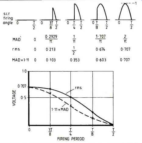
Fig. 1. If an average-reading meter is used to read the RMS value of an s.c.r.-controlled
waveform, the errors likely might reach 30%.
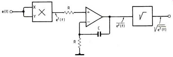
Fig. 2. Direct analogue squaring, filtering and square rooting appears easy,
but the output dynamic range of the squarer might have to reach thousands to
one.
M.a.d. is not the simple average --because for many waveforms and signals such an average is zero: there is no d.c. component.
Some people have termed the m.a.d. the "one-sided" average, but this is not very accurate. It is the absolute value that is relevant and its derivation can be written:
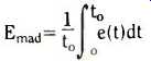
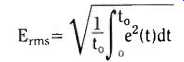
where to is the averaging time over which the operation is required. As the time passes, the average is up-dated every to. This amounts to what statisticians call the running average. Summing the squares of the instantaneous values, averaging, then taking the square root yields the RMS value:
Finally, there is a maximum value reached by a waveform as it varies about the zero mean. This is the peak value, EPk.
Historically, the ratio of the RMS value to the m.a.d. was called the form factor by the power engineers. It was briefly, discussed by Ken Smith in his "Power supplies..." articles.
A ratio of equal significance is that between the peak and the RMS. This is called the crest factor, and is a measure of the peakiness relative to the energy content of a given wave shape.
Summarizing these ratios:
Crest factor = Kc = Epk/Erms
Form factor = KF = Erms/Ermd
POWER
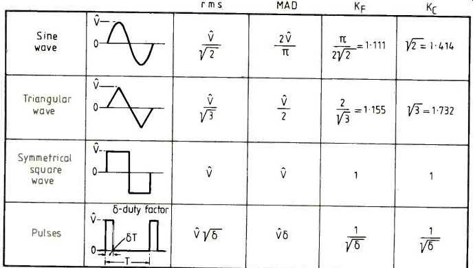
TABLE 1. A number of waveforms are here shown with their RMS mad., and Kc
values. A true-RMS converter will give the correct value, but errors increase
as the crest factor increases.
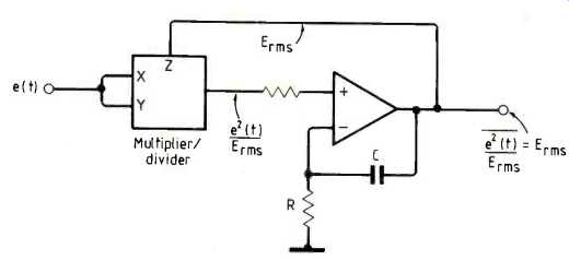
Fig. 3. The circuit block at the front end of an implicit RMS converter is
a multiplier/divider which yields a much lower output dynamic range requirement
An even worse misuse, is the meaningless statement "RMS power" seen on some specifications. There is an RMS voltage or an RMS current, but what can RMS power mean? Power is rate of using energy. This can vary with time and therefore an instantaneous peak power can be talked about and the average is the appropriate quality for a mean over a given time --not RMS
R.M.S TO D.C. CONVERSION
The measure of true RMS values must be a little more detailed than the simple methods common in a.c. meters. A direct application of the expression for RMS can be realised by analogue methods.
Figure 2 illustrates the use of a squaring circuit followed by an averager (i.e. a low pass filter with a characteristic time to together with a square-rooter. The main problem with this approach is the dynamic range. If you suppose that an input signal has a dynamic range of 100:1, (100mV to 10V, say), then the output of the squarer must have a dynamic range of 10 000:1.
By using a three-input multiplier/divider device, this problem can be overcome. Figure 3 shows the diagram of what is known as an implicit RMS computing circuit.
Because Erms is a very slowly changing voltage over the averaging time, it passes the averager very nearly unchanged. In other words, it can be used to carry out the division before the averaging. The output of the first stage now has a dynamic range of the same order as the input.
What now limits the signal handling capacity of these RMS circuits is the crest factor. Large crest factors means high peaks with rather small RMS values. The dynamic range has to be wide enough to cope without limiting-which would introduce errors.
Table 1 lists a few of the more common waveshapes with the appropriate factors and quantities. Noise and music waveforms are not deterministic in this way, and their statistical properties are all we have.
SPECIALIZED CHIPS
The Linear Device people have come up with chips that will do the whole job. All the designer has to do is watch the levels for the dynamic range and set the time constant component values for the desired averaging time. Analog Devices market the 5362, which is a dedicated RMS-to-d.c. converter.
Raytheon produce a logarithmic multiplier chip (the type 4200) which implements RMS measurements with a minimum of external components.
Finally, digital realization of the RMS conversion function has been implemented as one might expect. One way used an EPROM look-up table for the squaring operation, summed and stored a whole series of the squared data words (over a one second period, say) then passed the accumulated data, after division by the number of samples, to a digital square rooter. The final eight-bit word represented the RMS value.
References
1. Smith, K.L. 'D.c. supplies from a.c. sources'. Wireless World. 1985
2. RMS-to-D.C. Conversion Application Guide. Analog Devices
==========
(adapted from: Wireless World , Dec. 1986)