Automatically measuring the settling time of an operational amplifier using a programmable digitizing oscilloscope.
Settling time is the time required, following the initiation of a specified stimulus to a linear system, for the output to enter and remain within the limits of a specified error band centered on the ideal steady-state output value. For example, when testing the settling time of an op-amp, the system stimulus is a step change of the applied input voltage usually scaled so that the output swings between its upper and lower design limits.
When testing a digital-to-analogue converter, the stimulus is the application of a digital word or clocking signal that causes the output to swing between zero and full scale. Figure one shows how settling time is specified for these two applications.
TEST SETUP
Whether settling time is measured manually or automatically, the success of the measurement depends on the ability to resolve small variations of the base or top of a relatively large signal accurately. Typical error-band specifications, usually expressed as a percentage of final value, range between 0.1% and 0.001%. One of the best ways to make this measurement is to use the virtual ground method. This is a differential probing technique which allows signal error, i.e. settling information, to be analyzed directly. The general set up for this test is illustrated in Fig. 2.
At the virtual ground point, the signal under test is summed with a reference signal equal in magnitude to the final value of the test waveform but of opposite polarity. Voltage at the summing node, Etest, is zero when the signal under test Eout has the same magnitude as reference voltage E fef.
While the test waveform is settling error waveform Etest can be measured to determine the degree to which Eout has settled.
Since Etest=(Eout+Eref)/2, amplitude of the error waveform is reduced by a factor of two and the error band should be adjusted accordingly. Figure three illustrates the relationship between Eout, Eref, and Etest.
The signals could be summed in an oscilloscope using an A+B mode, but this would require a wider dynamic range than is usual for instrument inputs.
Summing with R12 allows clamp diodes D1,2 to be included to limit the maximum voltage excursion of Eout. This minimizes input overdrive and effectively controls test-system recovery time.
For this example, the device under test is a 741S high speed op-amp. This amplifier is to be used as an output buffer for an eight-bit d-to-a converter and is configured as a unity gain, inverting, current-to-voltage converter. Its full-scale output is-10 to +10V and the specified settling-time error band is 0.1% f.s.
The test system, Fig. 4, consists of a function generator as the stimulus, a test fixture for the op-amp, an automatic digital oscilloscope for measuring the response and a p.c. as the system controller.
The function generator must be able to produce a low distortion squarewave that has a specified settling time. When operated into high impedance, it should supply the required voltage swing into the test fixture.
Since the amplifier is used in inverting mode, the squarewave stimulus can also be used as the reference voltage applied to the summing network.
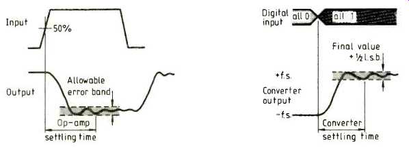
Fig.1. Specification of settling time measurements for an op-amp, left, and
a d-to-a converter, right.
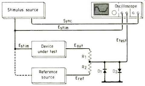
Fig. 2. Typical test set up for settling-time measurement. This method allows
signal error to be analyzed directly.
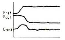
Fig. 3. Test waveforms for settling-time measurement. Waveform Etest represents
the degree to which the E., has settled.
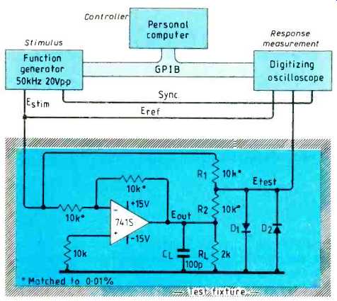
Fig. 4. Set up for automatic settling-time measurement of a high-speed op-amp.
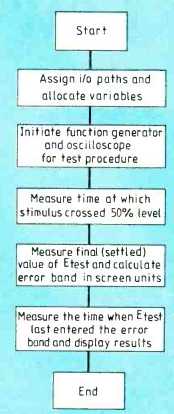
Fig. 5. In the test set up of Fig. 4, a computer controls the measurement.
This flow chart outlines the program requirements.
The test fixture is a carefully laid-out PSB containing the components shown in Fig. 4 and a socket for the op-amp. A BNC cable couples the stimulus signal and two test points allow direct connection of the oscilloscope probes to the test circuit.
A pair of 10:1 probes couple the test fixtures signals to the oscilloscope. The stimulus signal is input to channel one and error signal Etest is input to channel two. A BNC cables connects the function generator sync. output to the main trigger external input of the automatic oscilloscope; the sync. output triggers the oscilloscope.
Analyzing the Etest measurement path shows that its effective bandwidth is approximately 1MHz, due primarily to the high source impedance of the R_1,2 summing network taken with the clamp diode and probe capacitance. This bandwidth should be adequate for the measurement of the 741S op-amp, but may need to be reconsidered for other measurements.
MEASUREMENT ALGORITHM
When making an automatic measurement, the computer needs to perform the same sequence of operations as an operator performs when making manual measurements.
Measuring settling time is basically measuring the time between two signal sources; the necessary steps are shown in Fig. 5.
There are several important considerations to be made when designing a test system to measure settling time. System noise, stray capacitance, signal reflections, and ground path impedance can all cause significant measurement errors. Here are some suggestions that can improve measurement accuracy.
While the reference source selected depends on the specific measurement application, it is important that the source output has a low noise content. If a pulse generator or function generator is used, both amplitude accuracy and settling time must be well-defined and within the test requirements. This is particularly true if the stimulus signal is not accessible or is difficult to trigger on.
Resistors used to sum Eout and Eref should be good quality metal-film types and should be tightly matched to minimize the gain error at Etest. Select the resistors to a tolerance at least one order of magnitude better than the error band being tested. For example, if the error band is 0.1%, match R1, to 0.01%.
Alternatively, a potentiometer can be used to trim the summing network. Also, since R1 and R2 in parallel determine the source impedance of Etest their value should be made as small as possible without excessively loading the device under test.
Diodes should be Schottky barrier types.
Of primary importance are the diode's capacitance, reverse recovery time and current/voltage characteristics. Also, the diodes must be connected to a good, low-impedance ground.
Because the source impedance of the R_1,2 summing network is high and capacitance at the test fixture is unavoidable, the wrong probe can drastically affect wide bandwidth measurements. In many cases, the lower capacitance of a resistive divider probe or an active probe makes them an important addition to a test system.
Most oscilloscopes have a dynamic range of approximately five divisions beyond top and bottom of screen. To reduce effects of system noise and to improve resolution, the display signal should be scaled as large as possible. However, beyond 20 divisions of vertical deflection the recovery time of the oscilloscope will affect the measurement.
==========
(adapted from: Wireless World , Dec. 1986)