Increased range for the 8910 sound chip
Although the AY-3-8910 is specified to run at up to 2MHz, it seems to work well at 4MHz. The disadvantage is that in most cases, output frequency is clock frequency divided by 16 to 65,536 so a 4MHz clock produces a range of approximately 61 Hz to 250 kHz. Most of this range is inaudible.
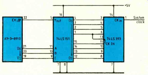
As shown here, a dual 4-stage binary counter gives a range of clock frequencies down to 15.625kHz; 1MHz now provides a range of 15Hz to 62.5kHz and at the lower frequencies, sound envelope attack/decay times are extended to minutes.
Two 8-bit i/o ports are built into the sound generator chip. Take D_0-2 from one of the ports and use them to drive the three address inputs of a 74LS151 eight-channel multiplexer. Outputs of the counter feed the multiplexer data inputs.
Now, sending a value between zero and seven to the generator i/o port selects one of eight different clock frequencies.
Mel Saunders, Leicester

D.s.b.-s.c. detector with p.l.l.
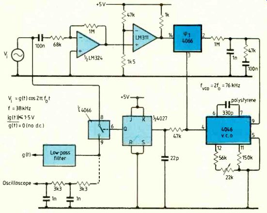
By adding a 'duty shaper' to the p.l.l. circuit shown on page 70 of the April 1986 issue, a signal synchronized with the suppressed carrier of a d.s.b.-s.c. signal could be generated. A duty shaper is a circuit which changes the 50% duty cycle of a sinusoidal signal to a new value (close to 25% in our case). Practically, its design depends on the carrier frequency.
I chose a circuit suitable for the 38kHz suppressed carrier found in stereo f.m. Its main purpose is to demonstrate that a simple RC active circuit could detect suppressed-carrier d.s.b. without the need for a reference such as a 19kHz pilot tone.
The LM324 op-amp acts as a class-C amplifier giving a train of pulses (but amplitude modulated). An LM311 comparator acts as a high-gain amplifier giving squared pulses with a duty cycle of around 25%, which is the optimum value to get the widest lock range as described in the April issue.
Voltage-controlled-oscillator output, delayed if necessary by an RC network, could then be divided by two using a 4027 JK bistable device.
The analog gate (4066) is used for synchronous detection. Finally, to recover the audio signal, gate output must be low pass filtered.
-Kerim Fahme, Autolight, Aleppo Syria

Transformer design-a simple method
Following the excellent article by Baert' examining trans former design in detail, I felt that a simple evaluation method would be useful for the experimenters working with unknown laminations.
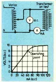
Wind 100 turns, or any convenient number, of insulated wire onto the former to be used. Insert the laminations and plot the magnetizing curve using the circuit shown. If a Variac is not available, then a tapped transformer or various power resistors may be used.
Draw a graph. As shown, the transformer should be operated just below the knee. From the graph, voltage at this point is read off. The number of turns used is divided by this figure to give the transformer's turns/volt rating, which will usually lie between five and ten turns/volt.
The winding wire gauge is found from wire tables using a figure of between 3 and 3.5A/mm^2 (1500 to 2000A/in^2).
P.J. Dinning, Newcastle-upon-Tyne, Northumbria
D.Baert, Designing small transformers, Electronics & Wireless World, Aug. 1985 pp17-19.

One-to-four-way telephone exchange
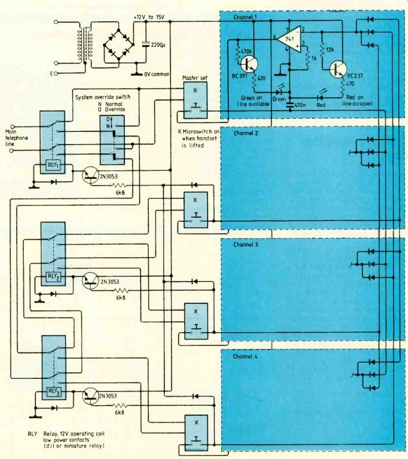
By eliminating the possibility that more than one set can operate at once, this exchange produces four lines from one without overloading. Once one of the four telephone handsets has been lifted, the line will not be released until the handset is replaced in its cradle. It also ensures privacy.
Monitor leds in each holster indicate whether the line is available. The single-pole, switches on each set can be either miniature microswitches or reed switches and magnets with the switch in the holster and the magnet on the handset.
Should a malfunction occur the system can be overridden so the line is always available.
Raymond Farrugia, Zabbar Malta

========
Don't waste good ideas
We prefer circuit idea contributions with neat drawings and widely-spaced typescripts, but we would rather have scribbles on "the back of an envelope" than let good ideas be wasted.
Submissions are judged on originality and/ or usefulness so these points should be brought to the fore, preferably in the first sentence.
Minimum payment of £ (x1.34 for $) 35 is made for published circuits, normally early in the month following publication.
Also see: RESEARCH NOTES
==========
(adapted from: Wireless World , Jan. 1987)