Using a notch filter with a canyon-shaped characteristic makes t.h.d. analyzers easier to tune and produces more consistent results.
B.J. SOKOL
============
SERVO NOTCH FILTER
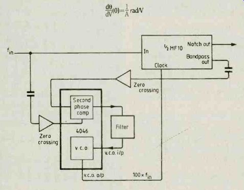
This servo notch filter tunes the notch to input frequency by forcing bandpass output to be in phase with the input. When bandpass-output is in phase the notch is in quadrature and thus nulls the input. Null is set at
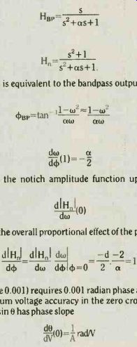
The effect of a phase error d4 is equivalent to the bandpass output BP locking the loop at phase (kb at frequency 1+ dw;
This frequency error moves the notch amplitude function up from null according to the derivative dw (0) which works out to-2/a. So the overall proportional effect of the phase error is …
Thus to get -60dB (amplitude 0.001) requires 0.001 radian phase accuracy.
This translates to a minimum voltage accuracy in the zero crossing comparators of 1 mV per peak volt input because V=A sin 0 has phase slope
dVt0l=AradN
============
Equipment for measuring total harmonic distortion is invaluable for checking amplifiers, tape-recorders and record stylii and should be used regularly to check high-quality reproduction systems for degradation (see ref.). It is also useful for designers and builders of audio equipment.
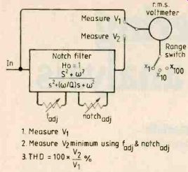
Fig.1. An adjustable notch filter and simple circuit measure t.h.d.
but manual adjustment of a deep notch filter can be difficult.
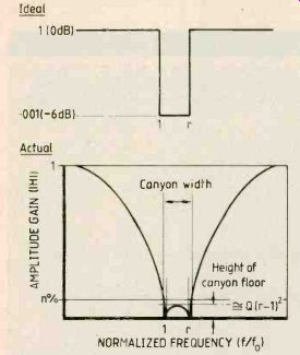
Fig.2. Using two notches placed close together results in a canyon-shaped
transfer function. Using such a characteristic instead of a narrow notch
filter makes t.h.d. measuring instruments easier to tune.
An adjustable notch filter and simple circuit, Fig.1., will measure t.h.d. but manual adjustment of a deep-notch filter with reasonable Q can be difficult*. My aim was to design a band-stop filter with at least 60dB rejection to allow fundamental suppression to 0.1%, and yet avoid using the usual two interacting controls for frequency tuning and depth trimming.
My first prototype-a notch filter which is automatically tuned to the fundamental frequency -- consisted of a 4046 phase-locked loop IC driving an MF10 switched-capacitor filter. This approach failed to meet my design requirements for the reasons shown in the panel but the design was capable of servo control of fundamentals down to 1% so it would be suitable for low-fidelity measurements.
Next I thought more carefully about the usually employed notch filter itself. This is a second-order filter with a pair of zeros on an imaginary axis. These zeros lie where the axis is cut by a circle around the origin passing through the poles. Thus both zeros and poles have the same resonant frequency and the filter transfer function is
At the pole frequency, this filter has a hole in its amplitude characteristic of a theoretically infinite depth for when s is -jw, the numerator of H(s) becomes zero. Narrowness of the notch surrounding this hole is what makes t.h.d. measuring instruments difficult to tune manually.
[* The need for tuning is especially acute if transducing equipment such as a record turntable or tape deck is being checked. Width of a 'canyon' filter floor allows a consistent and accurate measurement to be made despite moderate variations in the speed of the transducer motor. ]
===============
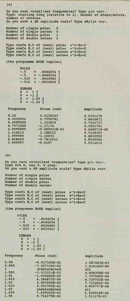
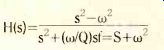
Fig.3. These two dialogues with Bode give the effect of a double notch,
with both Q values at 1 and with spacing of 3%. Dialog (a) reports at
l octave intervals to give an overall idea of the notch. In dialogue
(b), a fine analysis of the double notch around the centre is produced
by using closer frequency intervals of 0.5%.
Note: the 'canyon floor' is really at V r but this is close to (1+r)/2 when r is approximately 1. If r is 1+d, (1+r)/2 is 1+(d/2) and (1+(d/2))2 is 1+d+(d2! 4) which is approximately equal to 1+ d= r.
=========
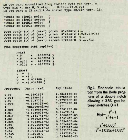
Fig.4. Fine-scale tabulation from the Bode program of a double notch
allowing a 3.5% gap between notches. Q is 1,
==========
But infinite suppression of the fundamental is not essential for practical t.h.d. measurement so I thought about what could be done to achieve a broader notch by sacrificing depth. I needed in effect not a notch but a 'canyon' in the amplitude transfer characteristic; a gorge not necessarily infinitely deep but with steep walls and with a certain width at the bottom.
Experiments with a computer program of mine called Bode (a listing is available), which tabulates phase and amplitude characteristics of any filter or transfer function, soon showed that two notches placed close together will produce just this overall transfer function.
Figure 2 shows such a transfer function using a graphical version of Bode. Of course the canyon bottom is not perfectly flat but maximum height between the walls can be limited to comply with the required figure of-60dB. Several applications of Bode showed that there is a trade-off between maximum floor height, filter Q (or steepness), and the distance (in frequency) between the canyon walls.
Investigating how wide one can make the floor of this canyon filter without unduly sacrificing its depth requires a little calculation. (Normalized frequency ratio rather than absolute frequency determines the slope of all filter curves, hence for example 6dB/octave.) Without losing generality, frequency (radian) of the lower of the two notches can be made 1 and of the upper notch, r. If distance between the notches is, say, 3% then r is simply 1.03. Assuming that each notch is symmetrical and with the same Q of 1/a (you will see why later) the transfer functions of the two second-order notch filters are, and s2+1 Ht S2+as+1 S2+r2 H2 S2+ars+r2.
Amplitude of these transfer functions is determined by substituting -jw for s and then calculating the square root of the sum of the squares of the real, and imaginary coefficients. Here, w represents relative frequency in the ratio 1:r so the rad/s versus Hz distinction need not be made.
Manipulation becomes rather complex but the points of interest- depth and width of the canyon floor- have a relatively simple expression. When the two transfer functions are multiplied and the combined transfer function is assessed for amplitude it turns out that the maximum value of the amplitude between the two notches, the highest point of the canyon floor, is exactly.
(r-1)2 (r-1)^2+ar
For small values of r-1, for example when the notches are fairly close together, and Q is 1/a, this is nearly equal to Q(r- 1)^2.
This is a pleasing result for if r is 1.03 and Q is 1 the height of the canyon floor is close to 0.032 which is less than 0.1%. A canyon filter consisting of two notch filters spaced apart by 3% will therefore suppress all frequencies by at least 60dB across a band at least 3% wide (a musical quarter tone); it will also be easy to tune.
Using the program reveals an exact result showing that a 3% gap between notches actually produces a canyon floor with a maximum height of 0.000873 (relative to an amplitude of 1) and that around this canyon there is a 4% wide frequency band throughout which amplitude suppression is better than 60dB, Fig. 3. This result exceeds the approximation so there is room in the design for a slightly wider notch, which is useful as can be seen from Fig.4.
The next issue to consider is steepness of the canyon walls. One must examine behavior of the double notch at frequency f=2 and above, which is where the harmonic distortion products are found. A neat approximation is possible when the notches are close together, for then they can be considered to be coincident at f=1 looked at from f=2 or above. Hence the transfer function is approximately the square of the transfer function of the single notch H1 above. If -jw replaces s in the formula and the result is squared, the expression for the amplitude at f=2 simplifies to 9/(9+4a2).
This approximate result indicates that for a canyon with Q values of 1, amplitude gain at the octave above the fundamental will be 9/13 or 69.2%. Using the program to find the exact values gives 68.1% for a notch spacing of 3% (Fig.3), confirming the approximation. By the time that f=4, where f is 4, the program shows that the amplitude value is 93.1% so there is little loss.
If Q were increased to two the above equations show that gain at the first harmonic (f=2) would be 90% while amplitude response at the highest point of the canyon floor would be less than 0.002 or 0.2% of the fundamental level. That might seem a better compromise but it was rejected because sensitive t.h.d. measurements are for most purposes more important than absolutely accurate ones. That is to say, 60dB fundamental suppression seemed more important than the partial loss of harmonic products due to a lower Q.
Returning to the former design with a Q of 1 and the notches 3% apart, you will recall that amplitude response is 0.681 at f=2. This represents a loss of first-harmonic content of about 3dB. Loss of higher harmonics is negligible. For reasons discussed in my next article, Q of the canyon filter may vary over a range of about 1.5:1 when it is tuned. This will result in a slight degradation of fundamental suppression, offset by an improvement in canyon steepness.
On paper, or using Bode, better results seem to be possible if asymmetrical notch filters with wp not equal to wz or two notches with unequal Q values are employed. Such filters can pass frequencies higher than the fundamental (the harmonic) to a greater extent at the expense of suppression of frequencies below the fundamental.
However, such methods are undesirable. False readings of t.h.d. are likely to result from a seemingly useful steep rise of the amplitude function up to f=2 and a very small amplitude response at and below f= 1.
For example if there were quite a lot of second-harmonic distortion the minimizing procedure outlined in Fig. 1 could well result in a frequency above the fundamental being chosen as f= 1 so that a little less fundamental than 0.1% but quite a lot less second-harmonic than 68% reaches the supposedly nulled r.m.s. distortion measurement. In other words one could null out some of the harmonics which would of course give a falsely low t.h.d. reading.
Thus it seems that a symmetrical double-notch filter with notches approximately 3% apart and with both Q values at around 1 will serve the purposes of my design very well. It should also be easy to tune.
Putting the double-notch filter to use will be discussed in a further article. A copy of the Bode listing can be obtained by sending a large s.a.e. to E&WW's editorial offices at Quadrant House, The Quadrant, Sutton, Surrey SM2 5AS. Please write Bode clearly on your envelope.
Reference:
Distortion on and off record by John Linsley Hood in Hi-Fi News and Record Review Oct. 1982 discusses how useful t.h.d. measurement can be in obtaining and monitoring high-fidelity equipment.
The ultimate extension to this concept would be to use a high-order elliptic or Cauer high-pass filter to pass only harmonics and suppress the fundamental- but then the problem of false nulling by placing the high-pass 'brick wall' where it cuts out harmonics clearly arises.
------------
Also see: Random-access phrase recorder
==========
(adapted from: Wireless World , Jan. 1987)