By JOULES WATT
JW warns that some theorems can endanger your health
The transfer of power from a generator to a load is one of the most fundamental operations in electronics and electrical engineering. I have worked with students who, once introduced to the Power Transfer theorem, tend to offer it up with reverence as a kind of panacea.
But as usual the picture is not quite so straightforward. A blind belief that the conditions for maximum power transfer always apply could get you into trouble. I mention a car battery later as an example. If you tried to match the battery, you might well end up with molten copper, boiling electrolyte and buckled plates! So, automotive engineers do not attempt to match the battery.
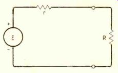
Fig. 1. Power in load is a maximum when r=R.
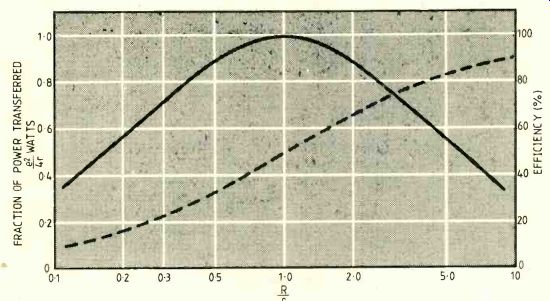
Fig. 2. Although power is a maximum when r- R, efficiency is 50%.
In case your memory is a little rusty on the theorem, I will briefly review it. In the " d.c." form, the theorem states: 'The maximum power is transferred from a source to a load when the load resistance is equal to the internal resistance of the generator.' This is easily seen from Fig.1 where, on finding the current and then the power in the load resistor, we have:
E 1-_ r+R power in R is z PR=I2R=(E R)z
If there is a maximum when R varies, this occurs when dPR/dR=0.
Now dPR E2[(r+R)2-2R(r+R)]- E2(r-R) dR (r+R)4 (r+R)3 and for this to equal 0, R= r.
You can see intuitively that, if a short circuit is applied, the power available externally is zero. For an open circuit, no current flows, so the power dissipated is again zero.
The simple analysis shows that in between these extremes the power available is a maximum when R= r. A plot of power in the load as R varies, r remaining fixed, shows this. See Fig.2.
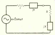
Fig. 3. Any active circuit of the type sup plying a load comprises a generator,
an internal resistance and a reactance.
Communications and radio engineers often call this equality of source and load resistances the matched condition. From the equation for PR, with R=r inserted, the maximum available power from a source e.m.f. E with internal resistance r is, E2 Pmax = 4r Some authors confusingly state that Pmax is "independent of the load". It is, if the equation is written as I have shown without R in it, but you have to remember that the maximum power is only obtained in practice if R is adjusted for the matched condition.
The theorem also applies to a.c. circuits containing reactances as well as resistance.
All active circuits that end up with a final pair of terminals supplying a load can be reduced to a voltage generator, plus an internal resistance in series with a reactance, as shown in Fig.3. This is an application of Thevenin’s theorem. (Norton's theorem is equivalent, but reduces the circuits to a current generator with an internal conductance shunted by a susceptance. Nor ton is said to be the dual of Thévenin.) If the source impedance of a single-frequency a.c. generator is z=r+jx and a load impedance connected to it is Z=R+jX, then the magnitude of the current is e V(r+R)2+ (x+X)^2
We are interested in the power dissipated in the resistive part of the load only, because the reactive part never dissipates any power.
This is given by e2R PR_ (r+R)^2+(x+X)^2
Without any differentiating, you can see that PR is greatest for given resistances when X=-x. This means whatever the source reactance value, you can maximize the power in the load by 'tuning it out' using an external reactor, equal to the internal one but opposite in sign, as part of the load. In fact, you have simply set up a series-tuned circuit in the system.
But matters are not as simple as they seem. Not many people are interested in a continuous single frequency. In communications, a whole band of frequencies occurs. In digital systems, it is even worse.
The band of harmonics is very wide for fast switching edges. Many digital engineers have come to grief by not realizing the `analog' nature of the networks, transmission lines and so on, in their systems.
The source e.m.f. and the real and imaginary components of its impedance in a Thévenin equivalent circuit vary with frequency. Even for fixed values of reactive components, L and C, the shifts of reactance with frequency are in opposite directions, relative to each other. For simple circuits this means that, at best, matching can only be obtained at one or two points in the band.
Usually, engineers cope with this by showing that a good compromise can be arrived at by equalizing the magnitudes of the source and load impedances. If Z is the magnitude of the load impedance and O its phase angle, then the real and imaginary parts are ZcosO and ZsinO respectively. The power in the real part is then e^2 ZcosO PR (r+ZcosO)^2+(x+ZsinO)^2 and if you differentiate this with respect to Z you can show that the maximum power is transferred when Z=z. The amount of power obtained now becomes, e^2 cosO Pmax_ 42COS2 1/2(B+OS) where z is the magnitude of the source impedance and O_S is its angle.
To return to my opening remarks, one decidedly does not try to match car batteries, whose r may be a few milliohms. The obvious reason is that, if the maximum power theorem is attempted, many kilowatts be come involved, half of which are dissipated inside the battery, which would soon boil, and explode, or something. The other half would melt the wiring harness.
Consider matching a power station to a city--an even more disastrous proceeding.
The efficiency can never be more than 50% for the maximum power condition, which would mean that half the megawatts produced would have to be dissipated at the power station.
What this means is that power engineers do not show much interest in the maximum power theorem. Their aim is to increase power transfer efficiency. As you can see from curve B in Fig.2, high efficiencies require R»r and this is certainly true in the application of car batteries and power stations.
So the discussion comes back to communications engineers, who do often re quire maximum signal power in a load. For example, the rather naive case of constant noise power in a system would require the signal power to be maximized for best signal-to-noise ratio to be obtained. But even in our field, this maximum condition is not always sought. In power amplifiers-- class B operation, for example- efficiencies of 70% or so might be obtained. In r.f. work with class C stages, even higher efficiencies are expected. 50% is not looked upon as very good, but that is the best you can do with maximum power matching as we have seen.
For good voltage regulation from a power supply, the source impedance must be very low compared to the load and any variations in it. Such supplies do not attempt the matching condition on this argument alone.
The regulation from no load to full (matched) load would be, Voltage at maximum load - 50% Voltage at no load which is very poor.
In conclusion, it seems that in small-signal, high-source-impedance, systems, we often consider the maximum power condition. In these, the money is in the hardware and not the energy consumed. In power systems, where costs of the energy dominate, it is efficiency that counts and that requires R»r.
------------
==========
(adapted from: Wireless World , Jan. 1987)