By R. HANSON
How to choose the best capacitor type for use across the a.c. mains supply.
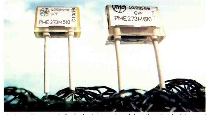
There is a growing need to fit interference suppression filters to electronic and electrical equipment, either to prevent the equipment malfunctioning due to noise on the mains or to prevent noise generated by the equipment going back into the mains supply. The last-mentioned requirement is governed by EEC directives and regulations in many countries.
Interference filters consist of one more capacitors used either alone or in conjunction with chokes in series with the supply leads. These assemblies can consist of individual components on a printed board or an encapsulated assembly in a box. These filters can present a safety hazard, the primary cause of which is the capacitors. Properly made chokes are an insignificant hazard. To make economical and physically small capacitors the dielectric within them is stressed at potential levels of 40V/um, which equates to 400kV/cm--sufficient to make one's hair stand on end. No other electrical or electronic components are stressed at such levels.
It is because r.f.i. capacitors are stressed so highly and operated from low impedance sources that they are a safety hazard. The numerous regulations around the world covering their use and operation testify to numerous capacitor failures. The failures have led to equipment fires and the possibility of electrical shocks to operators.
DESIGN OF X and Y CAPACITORS
There is no way that millions of capacitors can be made without having some failures in the field, albeit only one or two per million.
Having accepted that failures are going to occur the capacitor designer must design the capacitors to be intrinsically safe in that if short circuits do occur in the capacitor during use they should clear themselves--in other words the capacitor self-heals. In the event of the capacitor permanently going short circuit the component should prefer ably be made of fire retardant materials which do not sustain burning.
This doesn't mean that the capacitor will not bum, only that the burning will extinguish when the prime cause of ignition is removed by the circuit protection device. It is unfortunate that many of the capacitor designs on the market are not intrinsically safe. In the United Kingdom, unlike other countries, capacitors for r.f.i. suppression do not have to be approved, and only need to comply with the regulations (BS2135).
There are two basic classes of suppression capacitors, namely X and Y. The last type is for use where failure of the capacitor could lead to danger of an electric shock, and as a consequence is made to much higher standards than X capacitors and designed to withstand much higher test voltages. Class X capacitors are normally in the capacitance range of 0.01 to 1µF and go straight across the mains to filter symmetrical interference.
Class Y capacitors are normally in the capacitance range 1 to 4.7nF and go between live and neutral and earth and neutral to filter asymmetrical interference. Because Y capacitors are connected from the mains lead to earth they are limited to 4.7nF for most domestic equipment to prevent more than 0.5mA flowing to earth. (If the equipment is permanently connected to the mains the 0.5mA limit does not apply.) Class X capacitors are mostly wound capacitors using either paper, polyester, polycarbonate or polypropylene as the dielectric. Class Y capacitors may be either wound units using the previously mentioned dielectrics or ceramic capacitors.
Most countries have their own specifications and regulations relating to X and Y capacitors to maintain safety standards but sometimes they are used as import controls.
Specifications do not always keep in touch with the times and are sometimes written around a previous generation of capacitors, for instance the German specification VDE0560/7 for X capacitors.
Originally published in 1967 before metallized capacitors came to the forefront for suppression purposes, the specification was very good but 10 years later when metallized capacitors were used across the mains some types of approved capacitors failed disastrously. This was because on the 240V a.c. mains, there are present transient voltage spikes many hundreds of volts greater than the peak a.c. voltage of 240√2. Some lesser makes of early metallized capacitors had a very low tolerance to transients and as a consequence the VDE specification was withdrawn and replaced by another, VDE0565/1, published in 1979. This required 1kV a.c. to be applied to class X2 and Y capacitors for 0.1 second every hour of the endurance test at the rated temperature. These tests were also called up in IEC specification 384-14, published in 1981.
The problem of designing intrinsically safe X and Y capacitors depends on economics and physical constraints of size as well as the parameters of the design materials. As stated, given that millions of capacitors are in use and some are left on continuously 24 hours a day (tv sets which leave the filaments warm for instant picture, even some electric kettles), some capacitors are going to short. Short-circuit failures in metallized capacitors are reduced because even if voltage transients cause the capacitor to short the component clears itself.
This clearing or self-healing depends on metallized electrodes, burnt away around the short-circuit area enabling the capacitor to function normally. The self-healing is a complex physical and chemical process which even today is not fully understood, but will be described later. The metallized plastics paper capacitors are the only types that have this self-healing function, other types such as ceramic capacitors cannot recover.
While ceramic capacitors have a major disadvantage their basic construction does make them flame retardant; but providing selected materials and additives are used metallized plastics and paper capacitors can also be made flame retardant.
The two main problems encountered with capacitors for use at 240V a.c. on the mains are:
- ionization within the capacitor
- inability to clear faults.
IONIZATION IN VOIDS
All capacitors contain voids and these are a cause of ionization within the capacitor. The void which contains air has a lower dielectric constant than the surrounding dielectric and is therefore subjected to a greater voltage stress. Additionally the air in the void has a lower breakdown voltage than the surrounding dielectric. The minimum breakdown voltage for air under ideal conditions is approximately 340V and as the peak voltage of the 240V a.c. mains exceeds this, ionization can occur in all mains capacitors.
Once started it can rapidly degrade the dielectric and this in turn can cause the onset of ionization to start at a lower voltage than that which was first required. This is positive feedback, which leads to the dielectric breaking down and a short circuited capacitor.
The way to eliminate ionization within a capacitor is to
- make the air gaps very large
- make the air gaps very small
-reduce the voltage on the capacitor below the minimum to start ionization.
Obviously the first choice is possible, but makes for unacceptably large capacitors.
The second is also possible and while all wound capacitors contain air voids due to irregularities of the winding materials, these can be eliminated by vacuum impregnation of the capacitor with an oil. This was the traditional method but the requirement to have oil-tight seals and cases made the capacitors expensive and bulky. The modern version of oil impregnation is to use epoxy resin which is then cured to a solid. By impregnating the capacitor in a suitable mould the resin can be made to completely encase the capacitor element and no additional case is needed and this method becomes economical. The method is not a complete answer to all types of capacitors--only capacitors using paper dielectrics are sufficiently porous to impregnate properly.
Plastic films, because they have smoother surfaces which are more difficult to wet and inherently non-porous, cannot be satisfactorily impregnated to avoid ionization. Be cause of shrinkage of the resin when it cures, even paper dielectric capacitors contain some small voids which cause some ionization, but if metallized paper is used the ionization burns away the metalizing at these potential fault sites and in practice the fault sites are isolated. That is, the ionization within a metallized paper capacitor, providing it is below a specific level, does not increase with time but reduces.
The third method of preventing ionization is to reduce the peak voltage below the critical voltage of 340V. This is done in practice by winding the capacitor as two elements in series such that there is only 120V a.c. across each capacitor element. This method is done on several commercial designs and is very effective.
CLEARING ABILITY
The clearing ability of metallized capacitors, that is their ability of self-heal and to clear short circuits due to transient voltage or dielectric faults, is a complex physico-chemical process. While the number of clearings or self-healing operations occurring during the life of a properly designed-capacitor is minimal they do occur in ser vice. The clearing ability depends on electrode metal, electrode thickness, and dielectric film. The metal electrodes almost universally used for metallized film capacitors are aluminum evaporated on to the dielectric films, about 30nm thick in a high vacuum.
The films commonly used in mains capacitors are polyester, polypropylene, polycarbonate and paper. These dielectrics all have different clearing abilities which are also dependent on the metal film used. When a clearing occurs in a capacitor, the energy discharged through the short circuit causes the electrodes around the fault site to be evaporated away. This evaporated metal can still cause short circuits or low resistance paths unless it is oxidized to an insulating film. The only places that the oxygen can come from are either the entrapped air in the winding, and to prevent ionization this should be negligible, or from the dielectric itself. It has been found that those dielectrics which contain a high proportion of oxygen in their molecules do in fact have superior clearing ability to dielectrics which have little oxygen.
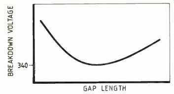
above: At large gap lengths the potential gradient is reduced and
few free electrons are available. At small gap lengths the gradient is high
but the mean free path of the free electrons generated is comparable to the
gap length and no additional ionization is caused by the electrons staking
other molecules. At intermediate gap lengths free electrons are generated by
the voltage gradient and these travel sufficiently far to strike and ionize
the air molecules. This generates other free electrons and an avalanche effect
occurs causing large current to flow.
Another important criterion is to have a high hydrogen to carbon ratio as this pre vents carbonization which can in turn lead to low resistance paths in capacitors and additional clearing discharges. The temperatures reached during self healing are in the order of 600K and at these temperatures the aluminum electrodes are easily evaporated and can react with oxygen in the film to form an insulating oxide.
The empirical formulae for the commonly used capacitor dielectrics are:
- paper (cellulose) C6H1005
- polyester (polyethylene terephthalate) C10H804
- polypropylene C3H6
- polycarbonate C16H1403
- polystyrene C81-18
Paper has the highest oxygen content followed by polyester, and experience confirms that paper has the best clearing properties, followed by polyester.
Polystyrene has a low hydrogen to carbon ratio, no molecular oxygen, and as a con sequence is not used as a metallized dielectric. Polypropylene has a high hydrogen to carbon ratio but no oxygen. It clears moderately well but the lack of molecular oxygen creates other problems. When plastic films are metallized with aluminum, the aluminum adheres by reacting with the molecular oxygen within the film. The absence of oxygen within polypropylene prevents good adhesion between the metalizing and the film and metalizing is easily rubbed off. To improve the adhesion to acceptable standards polypropylene films have to be pre treated prior to metalizing.
This pre-treatment consists of subjecting the film to a corona discharge, which physically abrades the surface and oxidizes the outer layers of film. While this process allows the aluminum metalizing to bond to the polypropylene, the excellent electrical properties of polypropylene are degraded only slightly.
The material requirements of an intrinsically safe capacitor or at least a very safe capacitor can now be defined:
--metallized paper dielectric
--epoxy resin vacuum impregnation
--flame retardant epoxy resin.
As well as meeting these material requirements the capacitor manufacturer must exercise rigorous quality control steps at each stage of production. There are differences between each manufacturer's own techniques. A significant improvement in reliability can be achieved by pre-clearing the metallized dielectric at a voltage in excess of what is seen by the dielectric in practice i.e. typically three times rated voltage. This pre-clearing is done by the better manufacturers before the film is wound into capacitors and effectively isolates all weak spots due to inclusions or holes. The pre-clearing eliminates or reduces to very low orders clearings which occur in the wound capacitor and this aids reliability as major clearings in a finished capacitor can damage adjacent layers which in turn causes other clearings to occur.
Another major problem of all metallized capacitors is the method of making contact to the metalizing. This is done by spraying metal from either a flame spray gun or an arc spray gun. Some manufacturers spray one layer of metal while others spray at least twice and sometimes three separate spray layers. These layers are different alloys chosen initially to bond to the paper/film metalizing while the final layer is chosen to be weldable to the lead wires.
While there are differences between manufacturers of plastics-film and paper capacitors with regard to reliability and performance, these differences--especially those of r.f.i. suppression performance--are marginal compared to the differences between different types of ceramic capacitors.
Ceramic capacitors are normally used as Y capacitors i.e. values up to 4700pF. To make economical and physically small capacitors, ceramic manufacturers have to use semi-stable ceramic formulations with high dielectric constant. These ceramic formulations are based on barium titanate dielectrics with a dielectric constant in the region of 1000, compared to four for an impregnated paper capacitor, three for a polyester capacitor and 2.2 for a polypropylene capacitor. This high constant is obtained by having a highly polar dielectric but as a consequence its properties and dielectric constant vary with time, frequency, applied voltage, and temperature.
The variation with time is of the order of 1% per decade and this change is trivial compared to the other changes. At first sight it would appear that as X and Y capacitors are designed for use across the mains at 50Hz, the variation of capacitance with frequency of a ceramic capacitor is of no consequence, but the frequency of operation of X and Y capacitors is not 50Hz but any frequency up to 300MHz or more. RFI capacitors are designed to suppress noise and if their capacitance falls with frequency their ability to suppress noise also falls.
The variation of dielectric constant and hence capacitance of ceramic capacitors with voltage, is different for each capacitor manufacturer and the capacitance may increase or decrease by as much as 20% from IV a.c. to 250V a.c. and this should be taken into account when selecting capacitors for use as Y capacitors..
By far the major cause of variation of capacitance is temperature with ceramic capacitors. Again these variations differ widely from different producers and compared to the room temperature capacitance some types may lose as much as 80% of their capacitance at -40 or +100°C. Alternatively at these extremes the capacitance can increase.
The performance of the other commonly used dielectrics such as polypropylene, polyester, paper are a model of stability compared to the semi-stable ceramics.
Polypropylene has the best frequency stability and has a capacitance stability of ±2% over the temperature of-40 to +85°C.
While polyester and paper lose a few percent of capacitance at 1MHz, their capacitance over the temperature range can vary by as much as 10%. These dielectrics are in a different class to ceramics where stability is concerned.
Where Y capacitors are concerned one essential requirement for intrinsic safety is capacitance stability. As previously stated many countries specify a maximum leakage current to earth of 0.5mA at 240V a.c. This corresponds to a capacitance of 6600pF. To allow for ±20% tolerance on capacitance, and tolerance on the mains voltage, a safe capacitance value is 4700pF. This capacitance value will give a certain performance of r.f.i. suppression and at room tempera ture there will be little difference between the performance of any of the plastics, paper or ceramic capacitors.
Over the working temperature range of -40 to +100°C plastics and paper capacitors will all have sufficient capacitance stability to maintain the r.f.i. suppression and keep the leakage current to earth below the regulation limit of 0.5mA. The ceramic capacitors, depending on the ceramic formulation used, will either have a markedly inferior r.f.i. suppression performance at some temperatures or alternatively they will allow the earth leakage current to exceed 0.5mA. It must be stressed that there are many ceramic formulations and it is conceivable that some types marketed may be able to maintain a reasonable r.f.i. performance over the temperature while at the same time keeping the earth leakage current within the allowed limits.
The main parameters for designing intrinsically safe capacitors or at least the safest possible capacitors can now be defined. They should be:
----stable; or at least the changes should be predictable and small with variation in temperature.
---- stable with changes of applied voltage.
---- predominantly fail-safe i.e. as open circuits. This requires good clearing properties.
---- flame retardant in the event of a short circuit failure due to misapplication or a manufacturing defect.
---- free from internal discharges.
The design which comes closest to meeting all the above parameters is the metallized paper capacitor encapsulated in a flame-retardant epoxy resin. These capacitors cover both X and Y applications and because of their excellent capacitance stability the r.f.i. suppression capabilities of Y capacitors do not have to be compromised against their safety requirements. These designs can meet all the current specifications but it is probably time that these specifications were re-examined and re written to assess the effects of capacitors over their full working temperature range and to recognize that semi-stable ceramic dielectrics can have capacitance variations with voltage and frequency.
Metallized paper capacitors have been available in various forms since the early 1900s. The modern form using metallized electrodes deposited by vacuum evaporation originated in Germany in the late 1930s while the aluminum metallized paper capacitor became available in the 1960s. The metallized paper capacitor has stood the test of time. Very few technologies have a 40-year production history in the electronics industry. But with the increasing emphasis on product safety, the metallized paper capacitor will undoubtedly be in production for the next 40 years because of its intrinsic safety advantages.
Ron Hanson is Waycom's product manager for capacitors.
==========
(adapted from: Wireless World , Oct. 1987)