By SIMON SHUTE
RDS--the v.h.f. Radio Data System and its implementation in the UK.
Radio receivers have been with us now for getting on for seventy years, and the technological developments which have led to the present variety of models, ranging from the wrist-watch and credit-card sized miniatures, through the vast range of 'portables', to the sophisticated hi-fi tuners and communications-type receivers, are well known to the readers of a magazine such as this one.
The fact remains, however, that most present-day receivers would be instantly recognizable to our great-grandfathers, who would find the tuning knob and scale quite familiar, albeit lacking the evocative inscriptions Allouis, Hilversum, and Droitwich! We take radio broadcasting very much for granted, the over whelming majority of the UK population tuning in at some time in any given week, but there is nevertheless a massive lack of understanding of such matters as waveband, frequency and modulation system among most members of the public. Most people seem to find their chosen station by trial and error, and are understandably reluctant to risk disturbing the tuning to find another one.
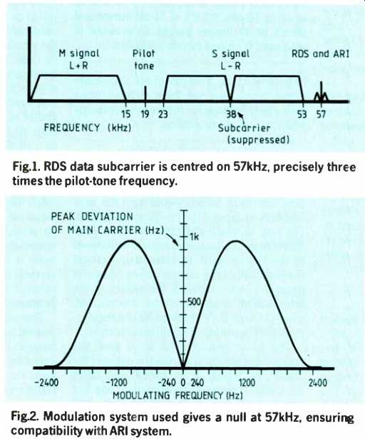
Fig. 1. RDS data subcarrier is centered on 57kHz, precisely three times the
pilot-tone frequency. Fig.2. Modulation system used gives
a null at 57kHz, ensuring compatibility with ARI system.
Contrast this with television. A television receiver is invariably equipped with some kind of preset tuning, in many cases gives a visual indication of the selected station and in no case that I have ever seen mentions Megahertz anywhere on it! As a result, viewers are entirely adept at dipping into the offerings of all four channels without giving it a thought--or at least not a technical one.
As more and more radio stations come on the air, and as the emphasis is increasingly on v.h.f./FM where the potential is so much greater, it can only get more difficult for the listener to find the signal of his choice. There are several separate but related problems:
- with many transmitters required to provide a national service, inevitably with over lapping service areas, how to identify the best signal;
- with many stations playing similar music, how to tell which station has been selected;
- for the mobile listener, how to benefit from the increasing number of 'filler' transmitters which are being built to fill in the remaining holes in the national v.h.f./FM services;
- again particularly for the mobile listener, how to find the local station serving the area he is passing through to get the benefit of the local information services;
- starting with a desire to listen to a particular station, how to find it without resorting to tables of frequencies.
It has been evident to engineers for many years that there was at least a potential solution to these problems, certainly on the v.h.f./FM band. Subcarriers of various kinds have been used for some time alongside the audio signals, and have provided several different applications. The idea that such a subscriber could carry coded information to identify the transmitter from which it emanated is not new, but no serious attempt had been made at drawing up the framework of international standards which would be an essential prerequisite for the receiver industry, which must look at a supra-national market for its products to be viable, until the European Broadcasting Un ion addressed the task in the mid 1970s.
The v.h.f. Radio Data System which will be described in this article is the product of the international working group which was set up by the EBU and in which the BBC was an active participant. The development and experimental period spanned the years 1974-1982, and several countries participated in the work. The objective was to develop a system which would be rugged enough to provide a vi able service under all practical reception conditions, but would be compatible with the millions of receivers which already existed in the hands of the public to the extent of not generating any audible interference. Experimental transmissions over the last decade have proved the viability of the chosen system, which was formerly endorsed by the EBU in 1984, and which was adopted as a recommendation by the CCIR in 1986. The internationally agreed designation for the system is RDS.
DATA SUBCARRIER
The frequency chosen for the data subcarrier is 57 kHz--exactly three times the frequency of the transmitted stereo pilot-tone, and synchronized to it in quadrature to its third harmonic for stereo broadcasts. In the case of monaural broadcasts, the data subcarrier 'free runs' but with the same tolerance on its frequency as for stereo (± 6 Hz).
This fixed relationship to the pilot tone is an important contribution to compatibility, minimizing the audibility of any beats being generated under multipath reception conditions or in receivers which are not properly aligned. The subscriber is modulated by shaped biphase-coded symbols which represent the 0’s and 1’s of the raw data-stream.
The modulation system used is two-phase phase-shift keying with a phase deviation of ± 90°, giving rise to a null at the sub-carrier frequency itself, with all the energy concentrated in an upper and a lower sideband, separated from the center frequency by the data rate. It is this spectrum-shaping arrangement which ensures compatibility with the ARI system3 which itself uses tones around 57 kHz. Figure 1 shows the baseband spectrum of the resulting composite signal including RDS, and Fig.2 shows the detail of the spectral components around 57 kHz.
Another important decision to be taken was the level at which the data subcarrier was to be injected. Clearly, an error-free signal will be easier to receive if the sub-carrier is injected at a fairly high level.
Equally, a high level of injection is bound to make it more likely that the data signal will interfere with the audio channel under non-ideal reception conditions, and 01 course the fact that the peak deviation of the radiated FM carrier is limited to ±75 kHz means that any deviation that is used by the data signal is not available for audio, thus marginally worsening audio signal-to-noise ratio.
Extensive laboratory tests and on-air trials have confirmed that the chosen level of about 3% gives satisfactory performance for data decoding, and is compatible with unimpaired audio reception, although a some what lower level is required for full compatibility with ARI. The system specification allows the injection level to be between ±1 and ±7.5 kHz, and the BBC's experience indicates that there is little to be gained by using more than the minimum value per mitted, with consequent benefits for audio compatibility under adverse conditions.
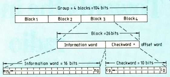
Fig. 3. 10-bit check-word provides information which allows detection of error
bursts of up to 10 bits, 99.8% of 11-bit bursts and 99.9% of all longer bursts.
Checkword is also used for block synchronization.
DATA SIGNAL
The 'raw' data rate of the data signal used to modulate the sub-carrier is 1187.5 bit/s, which is derived from the sub-carrier frequency itself by division by 48. Phase locking of all the signals in this way can lead to simplification in the design of decoders. The data-rate itself was constrained by considerations of compatibility and ruggedness, but the chosen figure gives adequate capacity for the various planned applications as well as allowing scope for future developments.
Data is transmitted as 16-bit words, each of which is associated with a special 10-bit checkword for error control. Four such 26-bit blocks form a 'group' and various types of group are specified to cover the various applications of the RDS system (Fig. 3). No additional bits are required for framing or other synchronization since this information can all be derived from the data stream itself by use of the special check-words.
An important feature of RDS is the flexible way in which the different group types can be inserted in random order to suit the requirements of the particular set of applications chosen. Each group is an entity in itself and can be decoded without reference to any other group.
Several group types are specified to cover all the defined data patterns, and it is up to the broadcaster to determine which groups, and in which order, he needs to transmit to satisfy the needs of the particular RDS service which he is implementing. It should be noted that less than half of the 32 possible group types have yet been defined, thus giving ample scope for future developments which are as yet unforeseen.
RDS AS A TUNING AID
The original primary objective of RDS was to open the way to the development of 'intelligent' receivers, which would help the user find his way around the broadcast spectrum.
The way in which the capacity of the RDS data stream is allocated is heavily influenced by this requirement. In order to understand the make-up of the various group types it is necessary to be aware of the nature of the information which is to be transmitted, which in turn is determined by the requirements of the proposed intelligent receiver.
The basic requirement is to give the receiver the ability to display the name of the station to which it is tuned and, after discussions between broadcasters and the receiver industry, it was agreed that eight alphanumeric characters would be used.
This eight character designation is known as the Program Service Name, abbreviated to PS. The coding used is in accordance with ISO 646, which makes provision for the various accented letters, as well as the Greek and Cyrillic alphabets required in some European countries. For the Roman alphabet the coding is effectively the same as ASCII.
To allow a receiver to find a station that the listener has selected, it is desirable to have a more compact and differently structured code. This requirement is met by the Program Identification code, (PI), which is a sixteen-bit code, unique to each radio station or network. Of the sixteen bits, the first four represent the country or origin of the broadcast, and the second four the service area (local, regional, national, etc.)
The remaining eight allow for 256 separately identifiable stations in each category.
The PI code is backed up by the addition of Alternative Frequency (AF) codes. These, each of eight bits, give the receiver information about other frequencies on which the same program can be found in adjacent areas. By doing this, the mobile receiver can keep its memory updated and be ready to retune to one of relatively few other frequencies when the one to which it is tuned fades.
It will be apparent that this is a much more practicable operation than having to rescan the whole band, looking for the appropriate PI code. Each possible v.h.f., m.f. and i.f. frequency is coded using a look-up table approach.
A further improvement to the potential ability of an RDS receiver to offer its user truly effective automation is provided by the so called Other Networks (ON), feature.
Consider the case of a receiver which is in use on a particular station, and the listener wishes to retune to another, perhaps to catch the News, having noticed that the time is just on the hour. With the information so far available, the receiver would again have to scan the band from one end to the other in order to identify the strongest signal which carried the appropriate PI code for the selected station. The time taken could well be annoyingly long.
The solution lies in transmitting along side each station's signal, information about frequencies on which other services, referenced by their PI codes, can be found. ON gives the receiver a sequence of related PI codes and associated frequencies for each of the other services available in the service area of the transmitter in question.
An RDS receiver asked to tune to another station will therefore know where to look!
OTHER RDS APPLICATIONS
After allowing the requisite capacity for the above mentioned primary applications, it was evident that there would still be a considerable amount of spare capacity in the data stream. Various other potential applications for broadcast data alongside a radio service were identified and their formats standardized by the EBU working group. The flexible nature of the RDS coding strategy means that unwanted features can be omit ted by the broadcaster with negligible penalty, and conversely that they can be added later in a compatible way.
The specified features are as follows.
Clock time and date (CT). A binary coded representation of time and date using Co ordinated Universal Time (UTC) and calendar date. A local offset is appended to allow the RDS receiver to generate an appropriate display of local time.
Program type (PTY). By allocating a different code to each of the various types of program--news, drama, pop-music etc.--it would be possible for a receiver to display the program type, or even to search for a particular type among the available broad casts.
Decoder identification (DI). A code could indicate which of various kinds of signal processing was in use so that the receiver could switch in the appropriate decoder, for example noise reduction.
Music/speech switch (MS). Broadcasters are well aware that it is impossible to satisfy the requirements of all listening conditions with a single speech/music balance. By identifying which is being broadcast, it would be possible for a receiver to switch between two volume settings which could be independently set by the user.
Program identification number (PIN). By giving each program a unique code, the receiver could be pre-programmed by the user to respond to it. An obvious application would be for unattended recording, but this would have copyright implications in most cases.
Radiotext (RT). Perhaps the most obvious of all, the datastream could be used to transmit text messages to the receiver for display.
Newsflashes, sports results, titles of music are among the possible applications. The RDS specification gives a format for a 64-character display.
Transparent data channel (TDC). The RDS specification anticipates the requirements to download generalized data (e.g. computer software) via the RDS channel.
Traffic information: RDS and ARI. ARI (Autofahrer Rundfunk Information) is in use in a number of European countries and provides a simple way of signaling broadcast traffic flashes to suitably equipped receivers.
Although RDS as a system can coexist with ARI--the signals do not interfere with each other--it is recognized that the availability of the RDS datastream will make the ARI signaling tones redundant. An RDS receiver would be able to extract the necessary switching information from the digital stream with no additional circuitry, thus saving the cost of a ARI demodulator. Codes have therefore been allocated in the RDS system which allow the precise emulation of the ARI functions:
traffic-program identification (TP) is an on/off switching signal to indicate to the receiver that this is a program which carries announcements for motorists: traffic-announcement identification (TA) is also an on/off switching signal, but which indicates that a traffic announcement is actually on the air, thus allowing automatic switching away from another radio station or cassette listening.
It will be clear that as the RDS signal is digital, each of these codes represents no more than a single bit in the bitstream. It is thus practicable to repeat the codes frequently in order to give the required rapid response. Countries which use the ARI system are planning that the tone signaling arrangements will ultimately be phased out as RDS receivers become the norm.
RDS GROUP STRUCTURES
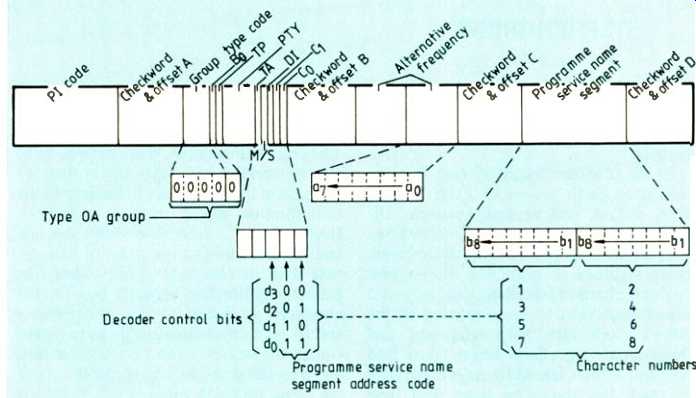
Fig. 4. OA group provides capacity for features shown. Other groups are specified
to include the remaining features.
Now that the various specified RDS applications have been described, the actual arrangement of the codes within the various different group types can be understood.
A group comprises 10^4 bits, made up of four 16-bit words, each with its own 10-bit checkword. As the bit rate of the signal is 1187.5 bit/s, it will be apparent that a little over eleven blocks are transmitted each second. Every block starts with the 16-bit PI (Program Identification) code so that the repetition rate of this important part of the RDS signal is guaranteed to be sufficiently high to ensure satisfactory operation of automatic receivers. The second 16-bit word contains five bits which define the group type, and thus point to the nature of the contents of the other bits in this word, and the other two words in the group. The five bits describe an A and a B version of each of sixteen group types. Of these 32 possibilities, only about half have been defined, leaving considerable scope for the development of new applications in a compatible way. The essential difference between the two main group types is that the B version includes a repeat of the P1 code in the third word of the group. This clearly raises the repetition rate, but reduces the rate at which other RDS information can be transmitted.
By way of example, Fig. 4 shows the make up of a type OA group. After the PI code, the first four bits of the second word define this group as a Type 0 group, and the fifth B., as the 'A' version of it. The microprocessor in the receiver will therefore 'know' what the meaning of the following bits is. It can be seen from the diagram that the next bit is the TP (Traffic Program) code, and the next five, the PTY code. The TA (Traffic Announcement) flag is then followed by the M/S (music/speech) switch. The last two bits of this word are used to set up a four-block sequence, so that the 4-bit Decoder Identification code, and the eight character PS (Program Service Name) can be spread over four consecutive 01A groups as shown.
The fourth 16-bit word contains the ASCII characters for this PS code, and the third, two coded 'Alternative Frequencies'. The way in which these AF codes are used is given in full in the published specification but essentially a look-up table is specified to convert between the eight bit binary numbers and the actual frequencies in use.
It can be seen from the above example that not all the various RDS features are accommodated in a single group. It is therefore necessary to transmit a mixture of group types to suit the applications in use by a particular broadcaster. By adjusting the repetition frequency of the different group types, the appropriate data capacity can be allocated to the various functions. For example, the group type containing the Clock Time code (CT) only needs to repeated once each minute.
IMPLEMENTATION OF RDS BY BBC
Once the specification for the RDS system had been finalized and agreed, there then existed a 'chicken and egg' situation. Receiver manufacturers were not keen to under take expensive development work on receivers for a service which did not exist, and broadcasters were reluctant to spend similar large sums on starting a service when there no receivers purchasable by the public.
To unlock this position, the BBC was involved in informal talks with a wide range of manufacturers through 1984 and 1985, and through these contacts, a level of confidence was built up which allowed the BBC to start detailed planning for a service. As details of the plan began to emerge, the receiver industry demonstrated a corresponding increase in confidence, and by March 1986, the BBC felt able to give the formal go ahead to the first phase of the implementation program in the certain knowledge that there would be at least some receivers available at or around the announced start date of October 1987.
The plan. In determining the precise details of implementation, it was necessary to balance a number of factors. The RDS specification provides for a wide range of features, many of which would require a considerable continuing input to render a viable service.
Similarly, receiver manufacturers were feeling their way, and looked for a package of features which would get the service off the ground, without involving an excessive amount of development.
It was also becoming clear that the first RDS receivers were going to be car radios.
Accordingly, the BBC planned to implement a set of features which would optimize the benefits obtainable from an automatically tuned car radio. In fact, these are the same features which would be required by an intelligent receiver, and so are in no way dedicated to in-car application. Additionally it was decided to implement the Clock Time and Date feature, since this could be done at little additional capital cost, and involved no continuous operating expenditure.
The RDS codes involved in automatic tuning are PI, AF and ON and of course PS is also included to give a positive read-out of the station name. In the case of the BBC networks, the information for these codes is generated centrally, and fed to the RDS encoders at transmitters by data links. In this way, the codes can be changed dynamically, which is necessary when, for example, the v.h.f. and m.f. services are 'split'.
CT is derived at each encoder site from a clock circuit which derives its reference from the low-frequency 'MSF' transmissions from Rugby.
Phased implementation. It became clear early in the planning period that it would not be practicable to muster the necessary re sources to equip the whole of the BBC's network simultaneously. However, the nature of RDS is such that it is vital for all the services receivable in a particular area to be coded, otherwise the intelligent receiver will have 'blind spots'. Having made the decision to spread the implementation geographically, rather than by service, it followed that the logical first phase was to cover England. In England, the pattern of broadcasting is less complex, with four national networks almost universally available, and the local radio chain forming an effective 'fifth network'.
Now that this first phase is virtually complete, planning effort is being devoted to solving the complexities of coding the various regional and 'opt-out' services which are broadcast in the national regions (Scotland, Wales, Northern Ireland) with a view to completing the installation program in a single second phase through 1988/9.
Travel information and RDS. The possibility of providing an ARI[3]-type travel information service using the RDS equivalent codes has been mentioned earlier, and the BBC has been conscious of considerable interest by the car radio industry in this feature. From the BBC's point of view of course, the car radio audience is a minority, albeit an important one, and it would not wish to commit itself to providing a service which did not measure up to the normal yardsticks of a public-service broadcasting organization. The use of the ARI system in West Germany has been studied, and of course an important difference is the way in which all radio broadcasting is regionalized. This allows stations to broadcast traffic flashes which are at least partially localized.
In the case of BBC Radio, the obvious channel to use as the primary channel for traffic flashes is local radio, and it is along these lines that preliminary planning is taking place. It is planned to conduct a limited experiment next year whereby a group of local radio stations will be equipped to radiate the TA and TP codes, which will also be linked into the BBC network services, so that a listener to, say Radio 3, could choose to have the program interrupted by traffic flashes from the local stations in the area he was passing through. There are various technical and editorial problems to be solved, but if successful, there is no reason why the service should not be extended nationwide in due course.
Acknowledgement. The author acknowledges the contribution of colleagues in BBC Engineering Division and in BBC Radio to the work described in this article, and wishes to thank the Director of Engineering for permission to publish it.
References
1. Design Principles for the VHF-FM radio receivers using the EBU radio-data system RDS. S.R. Ely and D. Kopitz. EBU Review April 1984.
2. Specifications of the Radio Data Systems RDS for VHF-FM Sound Broadcasting. EBU Technical Center, Brussels. March 1984.
3. ARI Automatic Radio Information. H.G. Duckeck. Proceedings of SAE Conference on Audio Systems, Detroit. February/March 1984.
Mr Shute is General Manager, Engineering, BBC Radio.
==========
(adapted from: Wireless World , Oct. 1987)