By MUHAMMAD TAHER ABUELMA'ATTI and NOURIA ABDULLAH HUMOOD
Connecting op-amps for unity gain increases oscillator frequency by minimizing gain-bandwidth product restrictions.
In 1985, Senani* proposed a new sinusoidal oscillator based on unity-gain op-amp configurations. Compared with oscillators using op-amps as finite or infinite-gain voltage-controlled voltage sources, this new approach produces circuits that work at much higher frequencies.
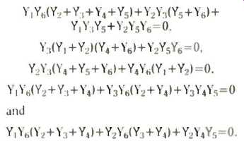
Consider the five configurations of Fig. 1. Assuming ideal unity-gain amplifiers, routine analysis yields the characteristic equations of the circuits which are, respectively,
By performing all possible permutations of these five configurations, two oscillator circuits result from each configuration, Fig. 2.
Oscillation conditions and frequency equations for each circuit are summarized in Table 1. Sensitivity is calculated using.
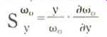
where ω0 is the oscillation-frequency parameter and y is the element of variation.
From Table 2 it is clear that the ten oscillators have low sensitivity characteristics.
Results are presented for only four of the oscillator circuits, Figs 3-6. but all ten designs have been built and tested using 741 op-amps. Good quality oscillations have been successfully produced and sustained at up to approximately 295kHz.
Each of the ten new active-RC oscillators shown uses two op-amps connected for unity gain, three capacitors and three resistors.
Connecting the op-amps for unity gain minimizes the effects of gain-bandwidth product, so higher oscillation frequencies are easily obtained. All ten circuits have low sensitivity characteristics.
--------- Muhammad Abuelma'atti and Nouria Humood are with the Department of Electrical Engineering and Computer Science at the University of Bahrain. Senani. R.. New RC active oscillator configuration employing unity-gain amplifiers. Electronics Letters. Vol. 21. pp. 889-891.
------------------
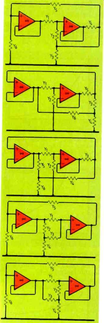
Fig. 1. Five oscillator configurations using 3p-amps connected for unity gain
to achieve higher oscillation frequencies.
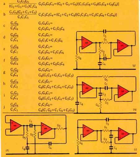
Table 1. Frequency and condition of oscillation for circuits of Fig.2.
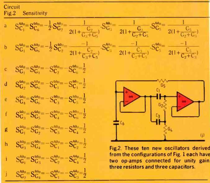
Table 2. Sensitivity equations for the ten oscillators.
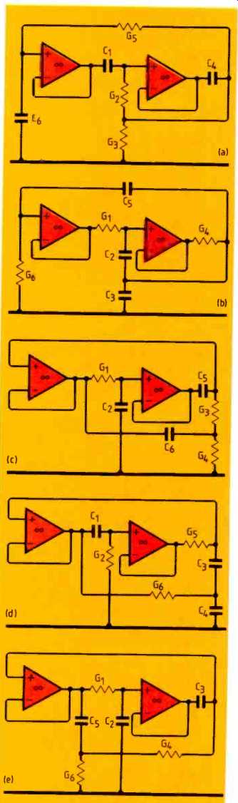
Fig. 2. These ten new oscillators derived from the configurations of Fig.
1 each have two op-amps connected for unity gain, three resistors and three
capacitors.
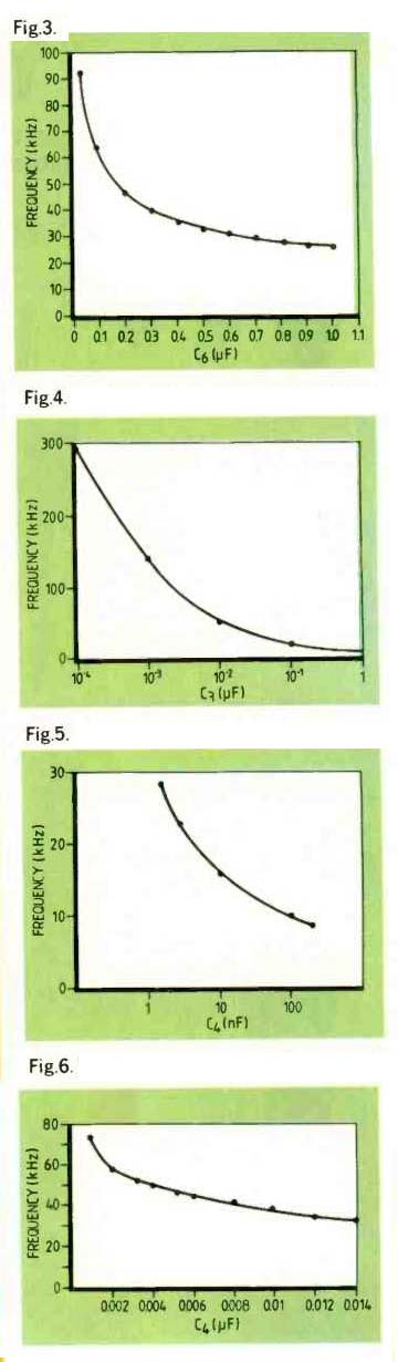
Fig. 3. Variation of oscillation frequency with capacitance C6 for the circuit
of Fig. 2(c). Resistor R1=1/G1=2.6k-ohm, R3 =1/G3 =129 ohm, R4=1/G4=147 ohm,
and capacitor C2=C5=1nF.
Fig. 4. Oscillation frequency versus capacitance C3 for the circuit of Fig. 2(e). Resistor R1=1/G1=1.8k-ohm, R4= 1/G4= 900 ohm, R6=1/ GE = 200 ohm, C2 = 100pF and C5= 5nF.
Fig. 5. Varying C4 in Fig. 2(g) gives this frequency curve for R1 =1/G1-166 ohm. R2= 1/G2 = 200 ohm, R6= 1/G6= 112k ohm, C3= 10nF and C5= 1nF.
Fig. 6. With the circuit of Fig. 2(i), varying C4 results in this frequency curve. Resistor R1=1/G1=289 ohm. R31/G3= 300 ohm, R6=1/ G6 17.7k-ohm, and C2= C5=1nF.
==========
(adapted from: Wireless World , Oct. 1987)