Radio frequency signal generators have taken on new roles. As well as testing radio performance they are now used for testing a variety of equipment from optical-fiber networks to satellite systems.
Signal generators, for any frequency, are part of a test chain. They inject a signal into a component or system that can then be measured for power or purity at various stages along a transmit/receive system. As the complexity of the medium increases, by using high frequencies or further distances, so the quality of the test equipment must increase. It should be noted that the test equipment should be a degree of magnitude better than the system under test in order to obtain meaningful measurements. So r.f. signal generators, as the first link in the test chain, have had to be improved over recent years to include microwave frequencies and achieve even lower distortion figures to test equipment which is itself of very high quality.
above: Synthesized generators, like the one above, offer low noise high frequency
stability and remote control and monitoring.
Perhaps the biggest change in recent years is due to the microprocessor and to digital electronics generally. It is now possible to synthesize signals of high speed and high purity without the delicate tuned analog circuits of previous generations. It has also led to remote and automatic testing and, like much other test equipment, the signal generator can be controlled from a computer and can communicate its status and operations back to the remote controller. Because it is the essential front end of a test system, it can be incorporated into that system and becomes just one part of, say, a spectrum analyzer or an r.f. 'test set'. This has the advantage that the signal generator and the measuring instrument are combined and the receiving instrument is automatically set up to 'expect' a signal that its own generator is sending. Alternatively a generator can be rack-mounted and integrated into a complete test set-up. However, it should be noted that the test chain is only as strong as the weakest link, so it is unnecessary to use a high-performance generator if the rest of the equipment is not up to its standard.
A typical test set-up is shown in Fig.1, where an optical-fiber cable is being tested and compared with a known, adjustable, level of attenuation. A similar technique is used to test a single component or a whole system.
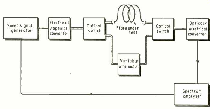
above: Fig. 1: A test set-up. The attenuation in an optical fiber is compared
with a known level. The technique is used to test a single component or a whole
system.
SYNTHESIZED R.F. GENERATORS
The performance requirements of modern radar and communications systems call for high-frequency signals with particularly good spectral purity. Hewlett Packard produce two synthesized signal generators with especially low noise characteristics: the HP8662A operates up to 1.280GHz, while the HP8663A covers an additional octave up to 2.56GHz. Phase noise (or s.s.b. phase noise is a measurement of the short-term stability of a frequency source. It is important because it can affect the performance of receivers, particularly where the desired signal is of lower strength but close to another source. The selectivity of a receiver can be reduced because of phase impurities in local oscillators. HP, therefore, have designed their generators especially with low phase noise, so that they can be used to measure the phase noise in communications systems.
The block diagram (Fig. 2) shows three main sections: reference, phase-locked loops and output sections. The reference section synthesizes many different frequencies from a high-stability 10MHz quartz oscillator.
Phase-locked loops use these reference frequencies to generate output frequencies of 320 to 640MHz in 0.1Hz steps. The output section modulates and amplifies the output signal and translates this to the required output frequency.
The reference section not only produces the frequencies that are used to derive the output waveforms, but also several local-oscillator frequencies for internal use by the PLL and output sections. All these are directly derived from the quartz oscillator, so the long-term stability of the instrument depends on this internal reference which is specified at 5 x 10^-10 per day after a ten-day warm-up. This represents a maximum drift of 0.25Hz/day. The reference frequency can be adjusted mechanically within a range of 20Hz to allow close calibration against a standard. For even greater stability, an external reference, such as a cesium or rubidium clock, can be used to give a stability of lin 10^11. Short-term stability or phase noise is kept to a minimum by the use of monolithic crystal filters in the reference multiplier chain. The mechanical mounting of these crystals is critical because any vibration can be translated into spurious noise microphonically. Typically, cooling fans in the instrument can cause offset sidebands, so the filters are mounted in special shock absorbers.
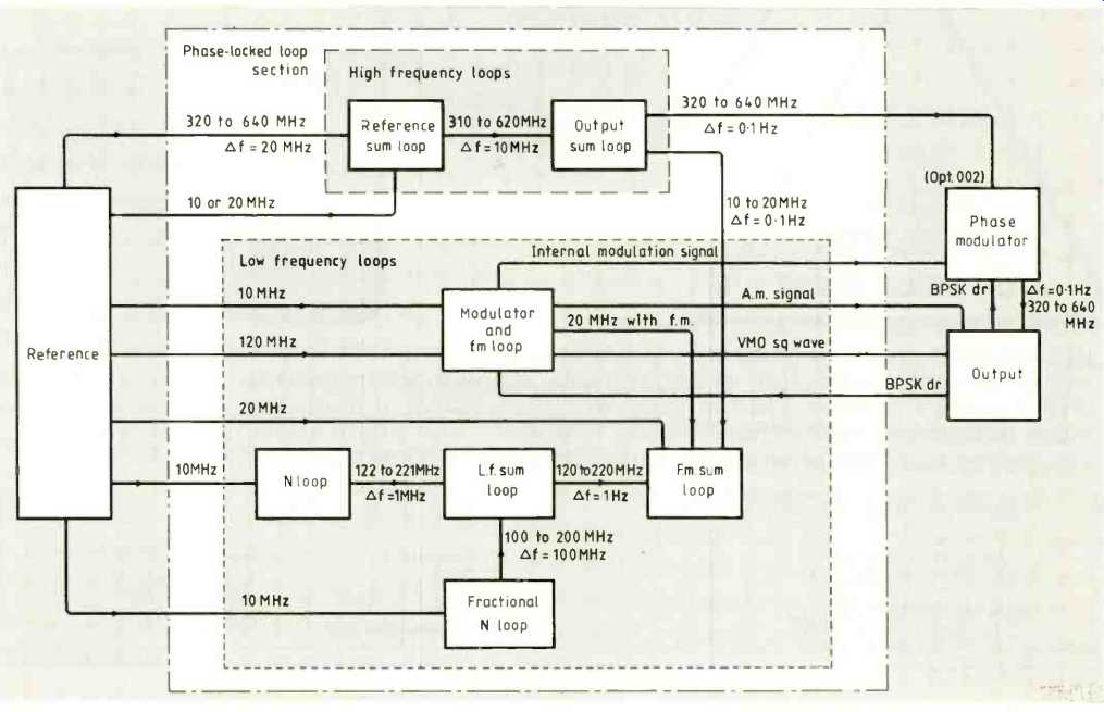
above: Fig. 2: Internal workings
of a Hewlett Packard 8663A generator. Three sections are the reference oscillator,
phase-locked loops and output
There are seven PLLs in the loop section. Indirect-synthesis techniques are used (contrasting with the direct synthesis of the reference section, which derives it signal by mixing, multiplying or dividing.) One of the high-frequency loops, the 'reference sum loop' tunes over a 310 to 620MHz frequency range, improves the re solution from 20MHz to 10MHz steps and provides 60dB of spectral filtering, reducing the spurious sideband levels from -40dBc to -100dBc (dBc--dB rel. to carrier). The 'output sum loop' is virtually identical and sums the 310 to 620MHz output from the reference sum loop with a 10 to 20MHz signal from the low-frequency loops, which output has a resolution of 0.1Hz which provides the output sum loop with 0.1Hz steps. Frequency modulation of the signal can be added to the waveform at this stage.
Both high-frequency loops use a special voltage-controlled oscillator, a switched-reactance oscillator consisting of five inductors switched in and out by pin diodes. This reduces the bandwidth needed for the varactor tuning diode and again helps to reduce noise. The signal from the output loop is directed to the output section by way of any modulators (a.m., FM, p.m., p.c.m., or b.p.s.k.) used for the final signal.
The output stage translates this signal from the PLL section into the desired output frequency by frequency doubling, dividing and mixing. Phase noise is increased in the multiplying stages and reduced in the dividing stages, but is kept to a minimum by careful design of the a.g.c. circuits and the input levels to the hetero dyne band mixer. Noise is better than -90dBc anywhere in the spectrum and is typically better than -148dBc.
Hewlett Packard produce a wide range of signal generators and much of this information was taken from their application note on phase noise measurement.
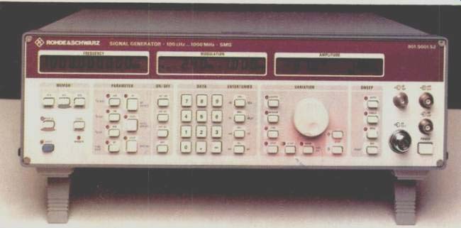
LOW-COST GENERATOR FROM ROHDE & SCHWARTZ
The latest signal generator from Rohde & Schwartz is the SMX, which at £4,300 incorporates GPIB remote control and r.f. overload protection to 30W and a memory capacity for up to 50 front-panel set-ups. The frequency range is 100kHz to 1GHz and so covers all frequency bands from 1.f. to u.h.f., with a resolution varying between <10Hz and <100Hz. Output level can be set with high accuracy from-137dBm to +13dBm with a total error level of < ± 1.5dB down to -127dBm. Non-interrupting levels of set tings over a range of 10dB can be used for squelch hysteresis measurements or testing a.l.c. characteristics with a level setting time of <10ms.
The instrument features versatile modulation capabilities; a.m. or FM separately or combined in a two-tone modulation; the a.m. mode also allows external pulse modulation. A modulation source is fitted as standard with a range of frequencies. The unit is shielded against received or transmit ted r.f.i. at a level well below recognized standards.
Another instrument from R & S is the SMC low-noise signal generator which shares many of the specifications of its fellows but offers a total error level of <1.5dB and very high spectral purity with s.s.b. phase noise of -140dbc at 20kHz from a carrier of 100MHz, and residual FM of <2Hz at frequencies up to 500MHz. The SMC also features a sweep with selectable start and stop frequencies, step size and timings for phase-continuous frequency changes.
SWEEPER FROM MARCONI INSTRUMENTS
A programmable sweep generator with applications in scalar network analysis, active measurement and ATE testing, the 6311, has been introduced by Marconi Instruments. It offers an extended frequency range of 10MHz to 20GHz in a single sweep. Features of the generator include high signal purity coupled with low harmonics, high power level accuracy, fast sweep and low residual FM It also provides a frequency accuracy of ±3MHz typically in c.w. mode, ±20MHz over any sweep width is provided for precision swept measurements by digital control circuitry. The instrument can be calibrated in 15 minutes using only a power meter and counter connected on the internal GPIB. In conjunction with the 6500 automatic amplitude analyzer and an auto-tester, the 6311 forms part of a complete scalar network analyzer system. Uses of the 6500/521 system are for microwave component and system manufacturers for testing cables, connectors, amplifiers, pin switches etc, and test applications in radar, telecommunications and satellites.
The high-purity signal coverage required for scalar analysis has been incorporated in the design of the 6311 to guard against serious errors in filter measurement caused by harmonics and subharmonics. Between 2 and 20GHz, harmonics and sub-harmonics are -40dBc and -60dBc respectively.
Coverage of 10MHz to 2GHz is provided with low harmonics of -30dBc with spurious signals below -40dBc.
Digital control of the 6311 is of use in active-device measurement, since the power level accuracy of ±0.5dB over 10MHz to 2GHz and ±0.4dB for 2 to 20GHz is necessary for the effective testing of the devices.
Microwave transistor and mixer manufacturers require accurate input-level measurements on amplifiers to compare gain compression, and mixer sensitivity for local oscillator drives with conversion loss.
For a.t.e. testing, where speed of switching signals is important, the instrument has a fast sweep of 15ms across its full range.
This meets the requirements for t.w.t. testing, radar system performance and military sub-system test racks.
The 6311 can also be used in calibration laboratories with such features as precision power resolution of 0.01dB, low harmonics and low spurious signals, rapid calibration and stable output power and frequency. The instrument incorporates a 68000 processor with programming facilities, either from tile front panel or through the GPIB. The sweep generator has internal and external GPIB links and includes comprehensive commands for operation over the system bus.
Manual operation of the 6311 is simplified by a 'soft-key' operation, from instructions on the instruments' back-lit l.c.d. Up to 20 sets of start-up modes can be stored in the non-volatile memory and quickly reviewed and selected.
GENERATORS FOR RADIO AND TV TESTING
Two synthesized generators from Philips are intended especially for radio and tv testing and are probably nearest to what a traditionalist might call a "sig. gen." They are intended as signal sources for testing v.h.f./ u.h.f. receivers. Frequency increment set tings allow random or sequential testing of a wide range of tv channels, irrespective of standards and including cable tv 'S' channels. They can also be used for testing domestic radio receivers and as a video modulator or signal source for testing video equipment. With a frequency range of 0.1MHz to 0.102GHz, the PM5390 has a resolution of 1kHz up to 1GHz and of 10kHz above that. It takes 80 minutes after switch-
on to settle in, after which its setting error is <1 x10^-6. Harmonic impurity is typically -35dB and non-harmonic -45dB. S.s.b. phase noise is -100dBdHz at 20kHz from the carrier. It offers a wide range of modulations, including a.m., FM, video and sound carrier. There is an input for external a.m. or FM and for an external video source or sound carrier. Easy-to-use front panel controls can select frequency, increment, sweep time, level and change in level. Each of these selections has its own display. The instrument has a built-in GPIB and can be control led remotely.
The PM5326 is especially suitable for radio and tv development laboratories and those involved in sensitivity and selectively measurements. For service workshops and educational purposes it has four wobbulators (sweep generators) for i.f. alignment and FM receivers. The 5326 offers a frequency range of 0.1 to 125MHz in nine push-button ranges. The frequency can be set on the 5-digit display to an accuracy of 1 in 10^4. The r.f. output is electronically stabilized to 50mV into 75 ohm, and can be calibrated and continuously attenuated to over 100dB. Variable and fixed markers can be added to a wave to positively identify reference frequencies. The built-in frequency counter can be used to measure external sources.
MICROWAVE FREQUENCY SYNTHESIZER
Frequency synthesizers covering up to 500MHz bandwidth at frequencies between 0.5GHz and 4GHz, with high spectral integrity, are produced by Scitec Electronics Inc. and distributed by Lyons Instruments. The modular design enables even unusual requirements to be met. The VDS-G's design makes use of new techniques and devices to achieve excellent performance without signal multiplication, cavities, mechanical tuning, or crystal oscillators. It uses little power, and is simple, reliable and less vulnerable to shock and vibration. Exploration of surface acoustic wave devices make it a highly cost-effective system.
Construction takes the form of four modules, mounted on a fifth mother module. The reference generator module uses a s.a.w. resonator and also produces the step-size reference. The comb generator module drives the r.f. output module via a tubular bandpass filter mounted in the mother module. The r.f. module includes the v.c.o. and r.f. signal processing devices. Finally, the signal processor modules uses a combination of programmable dividers, low-noise loop amplifiers and a loop parameter network to accommodate changes in loop characteristics such as v.c.o. constants and division ratios.
This modular approach makes it easy to meet customers' specific requirements. All output frequency-determining elements are contained in the r.f. module and tubular filter. Similarly, the signal processing module circuitry determines user requirements, such as step size, frequency control word and the like.
Typical performance specifications include bandwidth of 20% standard, up to the 500MHz available, and step size of 500kHz, 1MHz, 5MHz or 10MHz. Switching speed is less than 1ms, spurious signals typically less than -70dBc and the s.s.b. phase noise floor -146dBc/Hz. The instrument is controlled through binary-coded decimal signals.
RACAL-DANA INSTRUMENTS
Racal-Dana manufactures a comprehensive range of synthesized signal generators offering a broad spectrum of performance and capability. Indeed the company pioneered the synthesized signal generator concept.
Their range combines stability, resolution, accuracy, and programmability of synthesizers as well as the low noise offered by more conventional analog generators. These generators are designed for a wide range of general and systems applications associated with radio communications testing, including selectivity and sensitivity testing of ultra-sensitive r.f. receivers. The Racal-Dana products are particularly suited to these applications because of their calibrated output-level characteristics, low v.s.w.r. and automatic leveling circuits. In addition, the overall design has been engineered to reduce leakage and r.f.i. to extremely low levels, typically less than 0.50. The generators offer a wide range of functions which allow their use for signal to-noise ratio measurements, as drive sources for mixers and bridges and for many other applications including automatic test systems. Frequency selection, spin-wheel tuning, and a choice of internal reference oscillators make the Racal-Dana synthesized signal generators a cost-effective solution to measurement and stimulus requirements in the h.f., v.h.f. and u.h.f. bands. Probably the best known of the Racal-Dana signal generators is the 9087, the highlights of which are: 10kHz to 1.3GHz with 1Hz resolution; exceptional spectral purity; internal and external modulation a.m., FM, phase, pulse and f.s.k. with simultaneous combinations; ± 19dB dynamic range with 0.1dB resolution; level accuracy better than ± 1dB; full GPIB control; and self-check and diagnostic routines.
Because of their low noise performance, the 9087 and its sister model the 3101, a low noise frequency-agile synthesizer, are ideal for use as local oscillators in satellite communications and for testing of v.h.f./u.h.f. receivers. High switching speed also enables their use for frequency-hopping radio testing.
As well as manufacturing signal generators, Racal-Dana also distributes equipment including products manufactured by Adret Electronique. Among the range of signal generators which Adret manufacture is the 742A, a 2.4 GHz high spectral-purity instrument. Launched as a high-performance generator available at a modest price, its excellent pulse modulation capability makes it ideal for certain radar applications.
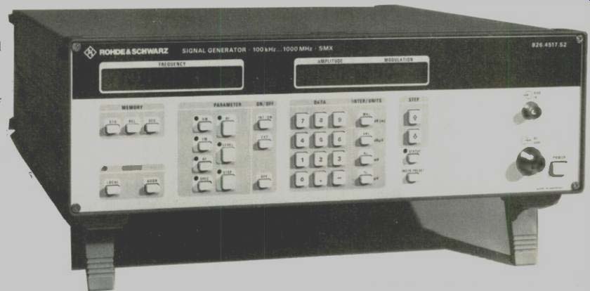
above: SMX generator from Rohde & Schwartz covers frequencies from
I.f. to u.h.f. and offers highly accurate output levels.
PORTABLE GENERATOR FOR MOBILE TESTING
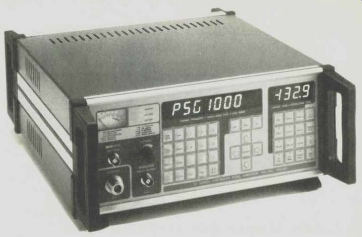
New from Farnell Instruments is the PSG1000 synthesized signal generator, a compact, lightweight, fully portable instrument for use in the frequency range 10kHz to 1GHz. The unit is designed to operate from an external 12V d.c. supply or any standard a.c. mains supply and its small size and light weight make it eminently suitable for field or bench use.
Full +13dBm (1V) output is available from 10kHz to 1GHz and an integral modulation synthesizer (10Hz to 10kHz) is provided. The instrument can also sweep carrier frequency/level and modulation frequency/ level between set limits. The generator has microprocessor control and can achieve the entire frequency range of the PSG1000 by direct r.f. synthesis with a resolution of 10Hz up to 128MHz and 100Hz from 128MHz to 1GHz.
Controls are of the sealed tactile membrane type. This results in increased reliability, prevents the ingress of dust or moisture and reduces r.f. leakage.
The front panel includes high-visibility led displays of output frequency, output level, modulation rate and modulation level.
An automatic sinad facility is included which provides a quick, simple and unambiguous method of measuring receiver sensitivity.
A.m., FM and p.m. are available and other features include facilities for external modulation, external reference frequency, re verse power protection to 50W, patented r.f. screening techniques and 100 non-volatile memories for front panel set ups or user defined modulation tones and selcal tone sequences for radio-telephones. In addition to manual data entry and updating, the PSG1000 is programmable via the standard IEEE488 bus or Hewlett Packard Interface Loop (HPIL).
Amongst other generators from Farnell are two synthesized signal generators, designated the SSG1000 (1GHz) and SSG2000 (2GHz). These two models also use micro processors and offer 10Hz resolution, low r.f. leakage, 1GHz testing of cellular radios, wideband coverage for testing aeronautical and marine communications, low phase noise for radio astronomy and ranging and location equipment, wideband phase modulation for satellite communications, sweep facilities for component testing and channeled operation for multichannel radio, with a fast lock speed for frequency-hopping transmission.
The entire range of the SSG1000 is covered without using doublers or multipliers with a frequency resolution of 10Hz: the SSG2000 achieves 2GHz by means of an internal active doubler system. Three manual methods of data entry and data updating are provided and the instruments are programmable via the standard IEEE488 or Hewlett Packard Interface loop. This is a low-cost serial twisted pair link that can communicate to a controller, which can be as small as a Hewlett Packard hand-held programmable calculator.
FUNCTION GENERATOR UP TO 2MHZ
An audio-style function generator has a frequency range of 0.1Hz up to 2MHz and so can be used for some r.f. applications. The Black Star Jupiter 2000 offers sinewave distortion of less than 1% at frequencies below 200kHz, with all harmonics below-30dB in the upper range. The frequencies are in seven overlapping bands with a vernier adjuster which can set the frequency to within 5%. Output levels are also in switched bands with vernier adjustment and the claimed level flatness is ± 0.2dB up to 200kHz and ± 1% to 2MHz. A sweep facility is provided. The instrument has also triangle waves and pulse trains ("square waves") and a t.t.l. output with a fan-out of 20 standard t.t.l. loads. The instrument is marketed in the UK by Altek Products.
RADIO FREQUENCY TEST SETS
Wandel and Goltermann make a range of level generators, but these are designed to work with their level meters and make up test sets. They are tuned externally through the meter, though some of them can have their output levels and frequencies set by front panel keypads or be controlled through a GPIB. They make a whole series of test sets that do incorporate r.f. signal generators.
Typically there is a spectrum and network analysis system that covers a frequency range of 100Hz to 180MHz and includes a sweep generator of a high specification.
There is also a range of distortion measurement sets for cable, radio links and satellite systems. The RK-100 white noise measuring set up can cope with up to 10,800 channels in a frequency range of 6kHz to 100MHz.
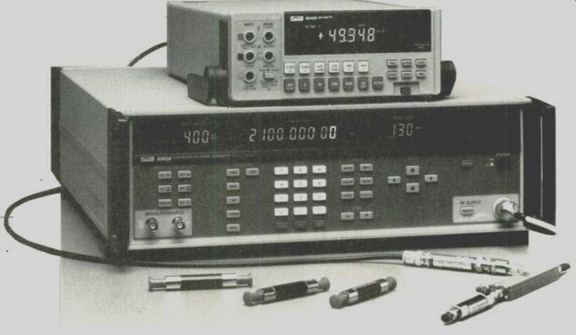
PULSE MODULATION AND 2.1GHz FROM FLUKE
The latest signal generator from Fluke has a frequency range from 0.1MHz to 2.1GHz; In addition, the 6062A incorporates a pulse modulator which uses GaAs switch techno logy to achieve rise/fall times of 15ns and on/off ratios of 80dB. The 6062A is designed for L-band testing in avionics communications and navigation.
Specific applications include secondary-surveillance radar, i.f.f, microwave links, global positioning systems and satellite communications.
The 6062A adds extended frequency to Fluke's family of low-cost signal generators and complements the performance of their general purpose 6060B and the low noise 6061A models, both of which operate to 1.05GHz. Its output level is adjustable over the range of +16 to -137dBm to 1050MHz, and +13 to -137dBm to 2100MHz. Absolute accuracy is ± 1.5dB. Amplitude can be displayed in volts, dBm, dB µV, or relative to any specific reference. The 6062A increases the modulation capabilities of the 6060 line with FM deviations to 400kHz. The pulse modulation on the 6062A has the high on/off ratio (80dB minimum) that is needed for radar simulations. Fast rise and fall times permit quality pulses of less than 5Ons duration. The low-noise capabilities of the 6061A are incorporated in the 6062A. Residual FM is guaranteed to be less than 6Hz (0.3 to 3kHz) and less than 4Hz in the frequency range of 245 to 512MHz. Non-harmonic spurious products are less than -60dBc to 1050 MHz, -54dBc to 2100 MHz; typical s.s.b. phase noise is -123dBc at 20kHz offset from a 500MHz carrier frequency. Other standard features on the 6062A include: AM, FM and phase modulation; a.c./d.c. coupled a.m.; full talk-listen IEEE 488 interface; 400 kHz FM deviation on 1050 to 2100 MHz range; relative frequency and amplitude nodes; step programming; a 50 location non-volatile memory; 25W reverse power protection; sub-harmonic external reference; Low microphonics due to robust construction; and self-diagnostics.
==========
(adapted from: Wireless World , Oct. 1987)