By S.J. GLEDHILL
The current state of signal generator design which, in common with most measuring equipment, takes full advantage of digital technique.
To appreciate the modern signal generator it is instructive first to review the evolution of signal generators.
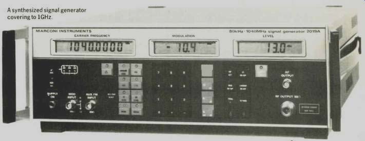
-----A synthesized signal generator covering to 1GHz.
FUNDAMENTAL-OSCILLATOR SIGNAL GENERATORS
The earliest signal generators were of the fundamental-oscillator type as shown in Fig. 1. A single r.f. oscillator was used and the frequency was changed by changing the capacitance or inductance of the tuned circuit. In the 1960s, transistorized instruments appeared for the first time: mechanic al tuning was still retained, but the instruments became more sophisticated and less clumsy. Electronic tuning has subsequently largely replaced unreliable mechanical methods.
Level control on very early instruments was not automatic. The operator had to reset the carrier level whenever the frequency was changed by an appreciable amount, a level control and meter being provided for this purpose. More recent instruments include automatic level control: a detector is used to derive control voltage, which adjusts the oscillator level or the gain of a variable-gain amplifier, to maintain a level output.
Frequency stability is poor and the signal generator can drift out of the pass-band of the receiver whilst a measurement is performed. Fundamental-oscillator signal generators do have their advantages however: there are no non-harmonically related spurious signals such as those experienced in other signal generator types.
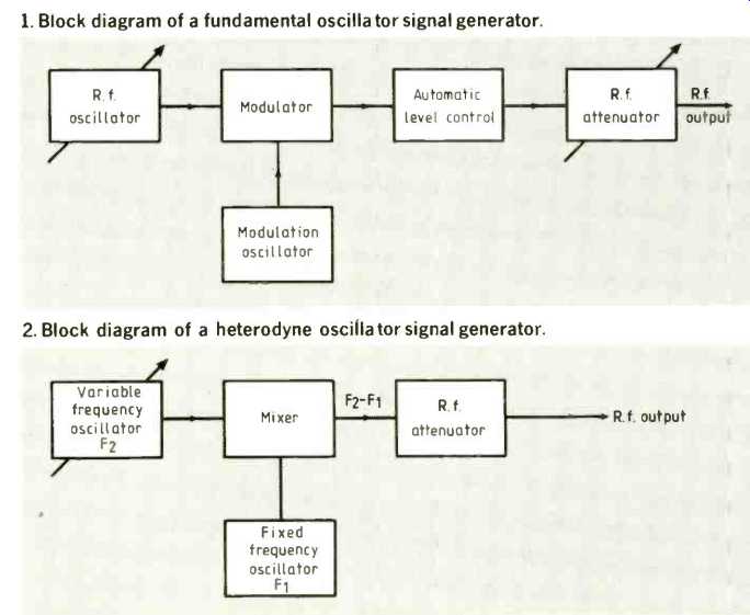
--------- 1. Block diagram of a fundamental oscillator signal generator.
----------2. Block diagram of a heterodyne oscillator signal generator.
HETERODYNE-OSCILLATOR SIGNAL GENERATOR
The problem with a fundamental oscillator is that it is difficult to cover a wide frequency range, particularly at the low-frequency end.
Incorporating many different oscillators into the design is possible, but this is expensive and, furthermore, the associated band switching is cumbersome.
A solution is to mix or combine two signals together. This technique is used in the heterodyne-oscillator type of signal generator, a simplified block diagram of which is shown in Fig. 2. A variable frequency oscillator (F2) is mixed with a fixed frequency oscillator (F1). The output signal is either the sum or difference of the two oscillator frequencies, the difference frequency (F2-F1) always being used. Wider tuning ranges are thus possible and band switching is reduced by using this type of design.
Although heterodyne oscillators can cover a wide frequency range, they can often also suffer from poor frequency stability. The output signal is not absolutely pure, since it is derived from two other signals which will be present to some degree at the output together with intermodulation products, even if filtering is used.
MULTIPLIED AND DIVIDED OSCILLATOR SIGNAL GENERATOR
To give a signal generator a wider frequency coverage the multiplier and divider concept was developed. The descriptions are largely self-explanatory.
With a multiplied-oscillator signal generator, only one low-frequency variable oscillator is used, so the cost and complexity is reduced. Cascaded tuned multipliers are used to provide the higher frequency ranges and a switch is used to select the required frequency range. A variable-frequency band pass filter may be tuned in synchronism with the frequency of the r.f. oscillator to select the required frequency. Frequency stability is poor, especially at the higher frequencies, since the effect of drift in the variable frequency oscillator is multiplied. A further limitation is that the output signal contains many unwanted sub-multiple frequency components.
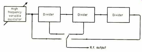
------- 3. Block diagram of a divided oscillator signal generator.
Figure 3 illustrates the principle of the divided-oscillator signal generator. This technique superseded the multiplied oscillator type when high-speed dividers became widely available. Like the multiplied oscillator type there is only one variable-frequency oscillator, so cost and complexity is reduced.
Signal purity can also generally be better because fairly simple filtering can be used to remove unwanted high-frequency components.
DIGITALLY-CONTROLLED SIGNAL GENERATORS
A solution to the drift problem is to digitally lock the r.f. oscillator to a stable crystal reference using a synchronizer. The inherent frequency stability of a crystal oscillator is thus imparted to the r.f. signal.
A variable-ratio divider synchronizer operates by dividing the signal generator output frequency down to the frequency of the crystal oscillator. The two frequencies are compared and, as the frequency of the signal generator drifts, a correction voltage is applied to the voltage-controlled oscillator in the signal generator.
Another method of synchronizing is to use a frequency counter to determine the current output frequency of the oscillator and to compare this with the required frequency, again a correction voltage being used to correct the tuned frequency.
Synchronizers were introduced in the early days of digital technology, but were soon to be superseded by fully synthesized signal generators. For stringent applications, where low sideband noise and spectral purity are critical, a fundamental cavity oscillator and synchronizer still provides the purest possible signal with no non-harmonically related signals. Such a generator is shown in Fig.4. The mechanical oscillator tuning is controlled by an electric motor, so the tuned frequency can be entered from the keyboard or through remote control. This provides the best instrument for testing receiver spurious responses in a programmable system or to provide a stable low noise signal.
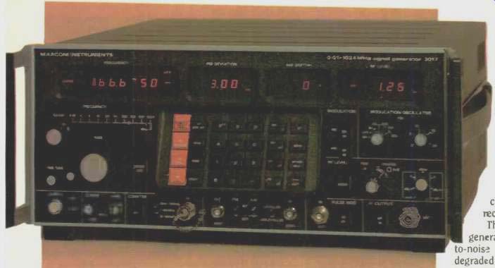
-----------4. Synchronized cavity tuned signal generator covering to 1024MHz
with very low sideband noise.
SYNTHESIZED SIGNAL GENERATORS
Most current signal generators now use one of several synthesizer techniques. Frequency drift is reduced and the frequency of tuning is set digitally to give precise rapid tuning. There are no moving parts, so size, weight and cost is reduced.
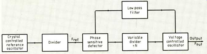
The heart of the majority of synthesizers is a phase-locked loop, working on the principle shown in Fig.5. Frequency Fou, is divided by the variable divider to give a frequency of Fut/N: this frequency is compared with Fret by the phase-sensitive detector and a correction voltage is applied to the voltage-controlled oscillator via a low-pass filter.
Locking of the phase locked loop is achieved when Fout/N = Fret. This method is known as indirect synthesis.
Unlike fundamental frequency oscillators, which have no spurious frequency components and a low level of noise, synthesizers generally have a number of spurious frequency components and noise is normally higher, although recent design advances have improved matters. A further limitation of a synthesizer is that the tuning changes in steps equal to Fret, which can be a major problem for receiver testing.
----5. Block diagram of a simple indirect synthesis signal-generator oscillator
using a phase-locked loop.
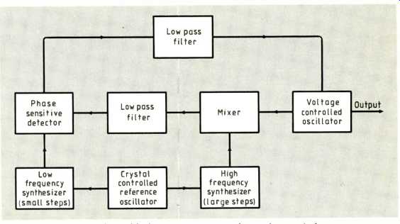
----6. A sum loop adds together two indirect synthesis loops to provide a wide
frequency range and superior resolution.
The indirect synthesizer detailed in Fig.5 can be made more versatile by including what is known as a sum loop in the correction loop, further benefits including a wider frequency coverage and superior frequency resolution. This is an adaptation of the heterodyne method described earlier. Figure 6 illustrates a simplified example, in which two indirect-synthesis loops are both refer red to the crystal oscillator: the mixer in the output loop allows the two frequencies to be added. In practice three or more loops may be added together and programmable dividers also incorporated. On p.978 is shown an example of a recent synthesized r.f. signal generator which covers to 1000MHz.
Synthesizer design is a classic example of compromise since there are two conflicting requirements. Good sideband noise performance is achieved by making the control-loop bandwidth wide, but resolution suffers.
High resolution can only be achieved if the control-loop bandwidth is narrow. A solution is the fractional-N method of synthesis which is used in many modern signal generators. A wide-bandwidth control loop is used, but to achieve high resolution the divider is rapidly switched between two integer division ratios.
By switching the dividers with different mark-space ratios, a range of frequencies between the two that would only be attain able without switching is obtained: side-bands at the switching frequency are removed by cancellation methods. Figure 8 shows a signal generator using the fractional-N synthesis method.
----8. Compact low-cost signal generators are possible using fractional-N synthesis.
Coverage of this instrument is 10kHz to 1GHz with 100Hz resolution.
SIGNAL GENERATOR SPECIFICATIONS
R.f. signal generators are available from many different manufacturers, covering similar frequency ranges, but with a bewildering variety of specifications. Inevitably, the quality of the specification of an instrument will generally affect the purchase price and the complexity of the instrument. It is therefore important to select the right instrument with the right specification for a particular application. The main specification points are reviewed Frequency range. A typical r.f. signal generator will cover from 10kHz to 500MHz or 1GHz. Inevitably the user will select an instrument to cover the appropriate h.f., v.h.f. or u.h.f. bands in question. An instrument covering to only 500MHz may be less expensive than one covering to 1GHz, but with increasing use of the 800-960 MHz band for mobile communications it may be unwise to restrict future applications.
The low-frequency range is important, since i.f. frequencies down to at least 450kHz may need to be covered. Certain radio receivers operate as low as 10kHz, so this aspect may also have to be considered.
Frequency resolution. A resolution of 100Hz is typical at v.h.f. and u.h.f. frequencies for an inexpensive synthesized instrument, but this can be a limitation when measuring the bandwidth of a highly selective circuit. 10Hz resolution is common on most mid-range signal generators: higher resolution is achievable but this inevitably leads to a high price, so it is wise to consider carefully what is adequate. 100Hz resolution is often more than adequate for routine production and maintenance tests on receivers, whereas higher resolution may only be necessary for research or development use. Frequency accuracy and stability. As we have seen, most modern signal generators are either synthesized or locked to a reference crystal oscillator. Key specification points of the crystal oscillator are: Temperature stability, warm up and ageing rate.
Short-term stability and noise are very important when evaluating the performance of single sideband (s.s.b.) radio receivers.
Audio signals in the receiver are generated by setting the signal generator to a frequency offset from the tuned frequency, an offset of 1kHz thus generating a 1kHz signal from the receiver. Any short term instability and noise in the signal generator will be apparent in the audio output and may invalidate a measurement.
Modulation. Most r.f. signal generators include amplitude modulation and frequency modulation as standard. Low-cost instruments may have just one modulation frequency, generally 1kHz. Mid-priced instruments may have five or six modulation frequencies, ranging from 300Hz to 6kHz, so that the extremes of the voice-frequency band can be evaluated. More sophisticated and expensive instruments include modulation oscillators with a much wider range of internal modulation frequencies. External modulation inputs are generally provided in all types of signal generator so it may be preferable to use an external audio oscillator rather than selecting a more expensive instrument with a wide-ranging oscillator built in.
Mixed a.m. and FM may also be required, in research and development laboratories, for the measurement of such parameters as the FM rejection of an a.m. radio. Phase modulation may also be required and signal generators increasingly offer this facility. Pulse modulation is also available for certain applications such as testing microwave radar systems at the i.f. (intermediate frequency) stages.
Modern radio receivers employ digital modulation techniques to a greater or lesser extent; military radios, for example, use digital techniques for encryption and data.
To test such a digitally modulated receiver a digital test signal is applied to the external modulation input of the signal generator. A restricted modulation bandwidth may distort the pulse waveforms.
Modulation accuracy also needs to be considered, since errors in the measurement of the signal-to-noise ratio of a radio receive can be considered if accuracy is poor. Modulation inaccuracy of the order of +5% is typical and this is generally acceptable.
Some lower-quality signal generators have an inaccuracy of up to ±20%, which can give errors of up to ±2dB when measuring signal-to-noise ratio.
Output level range. Maximum and minimum output levels both need to be considered. Most signal generators will be used to measure the sensitivity of radio receivers, so a minimum output level of at least -127dBm (0.2 microvolts e.m.f.) is commonly available.
The maximum output level may be important for certain applications such as measuring receiver blocking or measuring mixer intermodulation intercept points. For routine production and maintenance maximum levels of +6dBm or +13dBm will generally be adequate.
Output-level accuracy. Level accuracy is most important, especially since the sensitivity of a radio receiver will be specified according to the indicated output level of the signal generator. A typical specification is 1dB total level accuracy. Unfortunately, level accuracy can be misleading, so it is important to read the manufacturer's specification carefully. For example, the quoted level accuracy may only apply at one frequency, and frequency response uncertainty may also have to be added to obtain the total level uncertainty.
Another potential pitfall is that some manufacturers incorporate exclusion clauses such that the accuracy only applies over certain level and frequency ranges.
Finally, it is also important to study the output impedance specification, since a poor v.s.w.r. can lead to errors when measuring receiver sensitivity.
R.f. leakage. Leakage occurs because the oscillator within the signal generator always operates at maximum level. If the oscillator and attenuator are not adequately screened then signals may radiate from the oscillator into the receiver and sensitivity measurements would be invalid. This is especially a problem when measuring very sensitive receivers such as pocket pagers.
Moving the generator away from the receiver can sometimes cure leakage, but the only real solution is to ensure that a quality generator is used.
Spurious signals. Spurious signals can be at any frequency and they can totally invalidate the measurement of spurious responses from a radio. It is not always possible to differentiate between a spurious response caused by the radio or by a spurious signal generated by the signal generator. Typical specifications for harmonics are -25dBc to -30dBc, improving to -40dBc for more sophisticated instruments. Harmonics are generally not a problem because their frequencies are known and predictable; they can, however, be a problem when measuring filter frequency responses. The only signal generator to have no non-harmonically related spurious signals is the fundamental-oscillator type. Depending on the method of signal generation and the quality of design, the levels of non-harmonic signals will vary considerably. Non-harmonic signals on current signal generators can be as high as -40dBc or as low as -100dBc.
Residual FM. This is generally caused by random noise in the r.f. oscillator or synthesizer, and reduces the accuracy of signal-to noise measurements. It is useful to be aware of how manufacturers measure and specify residual FM An FM discriminator is used to demodulate the carrier and a voltmeter is then used to measure the output from the discriminator.
Since the output of the discriminator is noise, the measurement bandwidth has to be specified. Some manufacturers specify the noise over a band from 300Hz to 3kHz or from 50Hz to 15kHz, the former being applicable to communication receiver measurements, the latter to broadcast receiver measurements.
Another method of measuring the noise is to pass it through a psophometric filter, which has a frequency response tailored to simulate the sensitivity of the human ear to noise. A typical specification would thus refer to a CCITT telephone psophometric weighted filter.
Specifications differ between different types of signal generator but spurious FM figures of less than 10Hz are readily achievable on most modern signal generators, whilst 1Hz is available on expensive instruments.
Single-sideband phase noise.
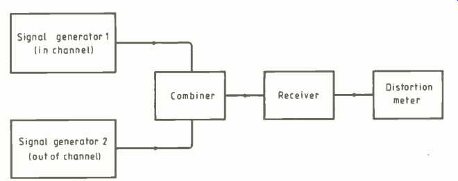
This is a very important parameter, to be considered if the signal generator is to be used for adjacent-channel rejection measurements. This test measures the ability of a radio receiver to reject a high-power signal in the adjacent channel. To carry out a measurement, two signal generators are used; one at the tuned frequency of the receiver and one set to a frequency one channel spacing above or below the receiver frequency, as shown in Fig. 9.
The level of the off-channel signal generator is increased until the signal to-noise performance of the receiver is degraded by a specified amount, usually from /2dB to 9dB. The single-sideband phase-noise specification is critical because unwanted noise sidebands give rise to erroneous results, as illustrated diagrammatically in Fig. 10.
Only higher-quality signal generators have specifications sufficiently good to allow sideband noise measurements to be made.
Measurements are generally only carried out during development, and not as a routine test, so it is not always necessary to have excellent sideband noise performance A typical, modern high-quality signal generator has a sideband noise specification of between -135dBc/Hz and -145dBc/Hz at a 20kHz offset from the carrier, permitting the measurement of adjacent channel rejection to better than 70dB.
Overload protection. When testing transceivers it is important to be aware of the fact that the same antenna connection is used for transmitting as well as for receiving and that it is very easy accidentally to turn the transmitter on while it is still connected to the signal generator. Many signal generators have been destroyed by an accident such as this--it only takes a momentary loss of concentration. Modern signal generators now incorporate reverse power protection to eliminate the problem.
SIGNAL GENERATOR FACILITIES
Microprocessors have had a dual impact on signal generator design. Ease of use is increased due to digital setting of parameter values, and specifications have been improved due to software correction and control of parameters.
To be able to enter the frequency of tuning directly would have been an expensive luxury 10 years ago. This has now become commonplace and is taken for granted. The user now demands additional facilities to improve ease of use, the two main ones being incremental control and storage of control settings.
Incremental controls are generally available to increment or decrement any parameter by an amount entered on the keyboard. Holding a key down will increment the parameter continuously--invaluable for tuning rapidly across a band or for changing output level when determining receiver sensitivity. A 'total shift' display which indicates the total increment is especially useful when measuring bandwidths, since calculation is not required.
Storage of complete front-panel control settings can be a great time-saver. Not only can the frequencies of a multi-channel receiver be recalled by simple key-strokes but complete settings, including incremental values, can be recalled as well.
Software is used to correct for frequency response variations and to linearize frequency modulation. A further useful facility which is becoming increasingly popular is a software-controlled clock, which can indicate elapsed time. This may be used to monitor instrument reliability or to schedule re-calibration only when absolutely necessary.
----9. Two signal generators used to test FM adjacent channel selectivity.
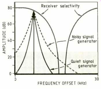
----10. Sideband noise on a noisy signal generator introduces noise into an
out-of-band channel measurement
CONCLUSION
Signal generators have changed dramatically in recent years. Very high performance and extreme precision are available, but at the other end of the market low-cost, high performance instruments are readily avail able. Perhaps the most dramatic illustration of the current state-of-the-art is that ten years ago a synthesizer was found in only a few development laboratories. Modern synthesizers are now so affordable that they 'become universally used for service and maintenance as well as for more demanding applications.
S.J. Gledhill is with Marconi Instruments at St. Albans
==========
(adapted from: Wireless World , Oct. 1987)