Frost protection
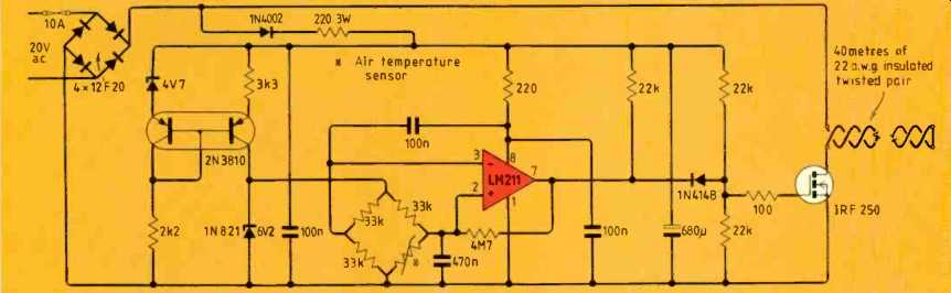
A length of wire and control circuit protect exposed water pipes against frost. When air temperature falls below about 1.5°C, the control circuit switches mains-isolated 20V unsmoothed DC into the insulated wire, warming it up. During heating, consumption is about 100W.
Twisted-pair wire tucked inside foam pipe lagging forms the heater. Ordinary insulated twisted-pair wire (23 SWC, 22 AWG) was used for convenience. With the 20V, 5A transformer, 40m of wire and components shown, the circuit will protect about 20m of pipe; the wire is wound round the pipe.
Power is switched to the wire when air temperature falls below about 1.5°C using a reference voltage, thermistor bridge, comparator and FET switch. For other thermistors, only the bridge resistors need altering to correspond to the thermistor resistance at 0°C (in this case 33k).
Should component failure cause continuous power to be applied to the wire, there should be no problems provided that the control components and transformer are adequately rated. Heating of the wire is barely perceptible to the touch.
------------------------
Centronics handshaking incompatibility
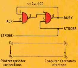
Centronics interfaces provide both acknowledge and busy signals, but only one of these is needed. Our Amstrad 128 looks for a busy signal and the Oric 4 color plotter that we wanted to use with it sends an acknowledge signal so the two are incompatible.
Adding a simple circuit to latch the busy line when the strobe appears and de-latch it when acknowledge from the plotter is sent can overcome this problem.
As far as we know the Centronics data strobe is always inverted but there are differences in the acknowledge and busy signals, which are only sometimes inverted. With other combinations of computer and printer, is may be necessary to invert one of the signals; the remaining two 74LS00 gates could be used for this.
Unfortunately there is no 5V supply line on the Centronics interface. Less than 20mA is drawn by the circuit so it should be possible to use the computer power supply in most cases.
--------------------------
Soft power switch
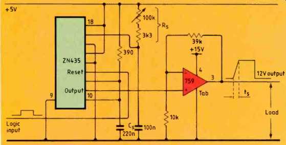
Controlling power circuits from logic-derived signals often requires gradual switch on with instantaneous switch off. This circuit provides control of the switch-on ramp using a d-to-a converter.
Logic low input at t.t.l. level resets the ZN435 data converter so the power output is off. When the input goes high the converter, wired as a 255-step ramp generator, ramps up to 2.5V. Duration of the ramp(t) depends on the clock frequency which is set by timing components R, and Cc; F= 1 212,C, where f is in Hz. Converter output feeds a non-inverting power op-amp giving 12V output for a 2.5V input. Any similar power op-amp should be suitable.
Other waveforms, such as a downward ramp for instantaneous switch on and gradual switch off, should be possible.
------------------
High-speed microprocessor link
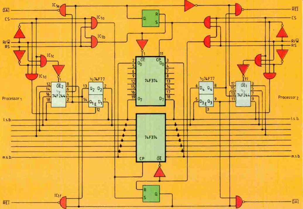
Conventional processors can be connected in parallel in a similar way to Inmos transputers. This high-speed link is basically a processor peripheral and relies on interrupts.
After receipt of the first byte, interrupts are disabled and the status register polled instead (alternately with the read/write register) until an end-of-communication byte is received.
Register selection is done using RS. When high, RS signals register reading/writing and when low, selects control/status registers. In the control register, bit zero enables data-available interrupt signal DA1 and bit one enables register-empty interrupt signal RE1. In the status register, bit zero flags the condition of DA1 bit one flags condition of eel and bit two and three signal data available and register empty, respectively.
With cs and RS, high and R/W low, IC1a output is high. This allows the lower F374 to latch data from the bus. It also sets the lower bistable IC to provide for the second processor and resets RI of the first.
When CS, Fs and R/W are high, gate IC1b enables outputs of the upper F374 latch. It also resets the upper bistable IC, resetting iii to the first processor and sending to the second. If now RS and R/W, go low, gate IC1a causes the lower two bits of the bus to be latched into half of the F77. These bits provide interrupt-enable signals to gates IC 1ef.
Finally, with cs and R/W high and RS low, gate IC1c causes latching of the interrupt-enable and status signals on the lower four bus lines. The second processor interface acts in exactly the same way.
I have not built the circuit. Provided that sufficiently high-speed logic is used, the only problem that I foresee is when one processor is reading from the circuit simultaneously with the other writing to it. Although the data transfer will take place, the associated RS bistable device will settle in an undefined state and may cause the reading processor to reread the same value. Provided that interrupt status is continuously monitored, this condition is unlikely to arise, especially if the processors run at different speeds.
Note that pin CP of the F374 must go high and low again before bus data becomes invalid. For most processors, cs and row signals will change before data is removed, but check this.
For high-speed work, for example with two 68020 processors running at 25MHz, 'F' logic ICs are recommended. Expansion of the circuit for 16 or 32-bit operation is simply a matter of adding F374 latches and feeding them from the existing OE and CP lines.
-------------------
Don't waste good ideas
We prefer circuit ideas contributions with, neat drawings and widely-spaced typescripts; but we would rather have scribbles on the 'back of an envelope' than let good ideas be wasted.
Submissions are judged on originality and/or usefulness so these points should be brought to the fore, preferably in the first sentence. We require a written statement, that the idea, or modification to an existing circuit, is your own work. Please keep a copy of your submission and mention whether or not you have sent the idea to another publication.
Minimum payment of 35 pounds is made for published circuits, normally in the month's following publication. We can arrange for an alternative reward of a two-year subscription if you prefer.
==========
(adapted from: Wireless World , Dec. 1987)