By HOWARD HUTCHINGS
Using an intuitive approach, closed-loop digital control of a linear system is easy to understand without in-depth knowledge of theory.
Closed-loop control is an important microcomputer application and a specialist area. Connecting a micro computer to an external device is an effective way of acquiring an understanding of computer control.
A study of dynamic systems ought to include exposure to differential equations, followed by familiarity with Laplace and z transforms. I do not intend to pursue these topics in this hierarchical way since only one student in ten is likely to benefit from this approach.
This article demonstrates how to interface a linear system--a DC motor--to a digital computer. To keep the discussion lively, mathematical explanations are auxiliary to the main text and mathematical methods are only used when essential.
Provided that the system to be controlled is selected carefully, Basic is a reasonably effective and attractive programming language. It permits rapid implementation of control algorithms, and is easier to learn and use than assembly language.
OPEN-LOOP CONTROL
The primitive concept of sending bit pat terns to the outside world can produce remarkably sophisticated electronic projects with a minimum of hardware, principally because most of the problem is solved using software, Fig. 1. Program 1 is a simple piece of Basic software for sending keyboard input to the motor controller through the v.i.a. port.
Bidirectional control of the motor is possible using a split-rail supply and power amplifier, Fig. 2. For convenience I used a complete ZN425 digital-to-analog converter instead of a binary-weighted adder. A signal of denary 128 applied to the d-to-a converter through the computer's parallel output port represents 0V at the motor terminals. Buffering between the d-to-a converter and power amplifier provides voltage gain and offset adjustment.
In the following example, interfacing is done through a 6522 v.i.a. To count shaft revolutions, an encoder disc mounted on the motor shaft interrupts infrared light from an optical switch containing a led and phototransistor.
Maintaining a software-controlled shaft-revolution counter reduces cost. It also permits the problem to be solved using the v.i.a. timer/counter facilities, which is instructive and not too time consuming.
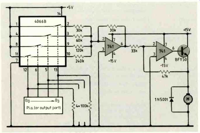
Fig. 1. Hardware for computer speed control of a DC motor is simple- most
of the work is done by software. Diagram courtesy of Loveday, Practical interface
circuits for micros, published by Pitman.

Program
1. Using keyboard input to control motor speed. Program
2. Motor speed and
digital revolution counting. Program 3. Closed-loop control.
above: MATHEMATICAL MODEL
above: EFFECT OF THE CONTROLLER
MEASURING ROTATIONAL SPEED
Hardware for measuring rotational speed is simply a pair of Nand gates providing the necessary signal conditioning, Fig.3. Gates with Schmitt-trigger inputs (74132) improve the pulse shape feeding the computer.
To restrict external electronics to a minimum, both timers within the v.i.a. are needed, one to produce a known-width gating pulse and the other to count the number of pulses during the gating period.
Timer 12 of the v.i.a. has two operational modes controlled by bit 5 of the v.i.a. auxiliary-control register, ACr. Setting this bit high causes timer 12 to decrement each time that control-line PB goes low.
Loading of timer T2 with 65535 is done by Poking 255 into low-order latch A+8 and high-order counter A+9 respectively. Timer T1 produces an output on line PB7 in monostable mode. In this mode, PB7 goes low for a period determined by the contents of registers A+4 and A+5, which constitute timer Ti.
Consider counting pulses from the opto electronic switch for 60ms. Since number N loaded into the computer is measured in microseconds, the counter is loaded with 60 000. This number is represented in the computer as two bytes. For the most-significant value in A+5, the byte is INT(N/ 256) and for the least-significant value in A+4, the byte is N-2561INT(N/2561).
In the previous software example, timer T1 is loaded with 60 000 by writing POKE A+4,96: POKE A+5,234. When timer Ti times out. a flag is raised in interrupt-flag register A+13. This flag is tested by the logical And function.
Finally, the number of pulses counted is the difference between 65535 and the current content of timer T1.
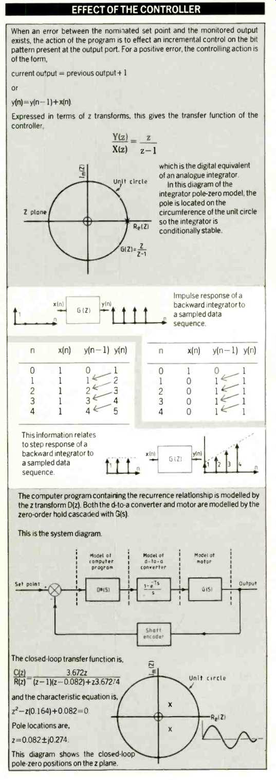
--------------Since the poles are located within the unit circle, the system will be stable. Transient response of the closed-loop system may be obtained by expressing the z-transfer function as a recurrence relationship.
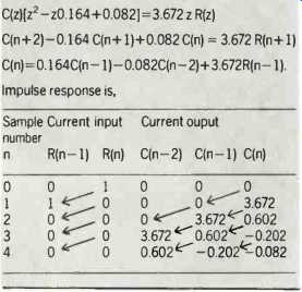
Proceeding as before,
SPEED MEASUREMENT USING ENCODER DISC
Consider an encoder disc with 100 lines on a motor shaft rotating at 120rev/min. Each second. 200 lines interrupt the opto electronic switch slot (120 x 100/60).
By allowing the count to be maintained for 60ms, the counter will record a count of 12, i.e. 60 x 10-3x 200, which represents one tenth of the true speed. To convert to true speed, the recorded count is multiplied by ten, or alternatively, the ratio and proportion,
60ms/ 60s = [c/100] / [rev/min]
is used. Here the true number of revolutions per minute is 10c. Program 2 illustrates motor control with revolution counting.
Resolution could be improved by increasing the count period up to about 65ms using the timer in the 6522 v.i.a. or by increasing the number of lines on the encoder disc. One problem is that the longer the time spent counting, the shorter the time available for controlling. While pulses are being counted, the motor effectively runs under open-loop conditions so there must clearly be a compromise between stability and resolution.
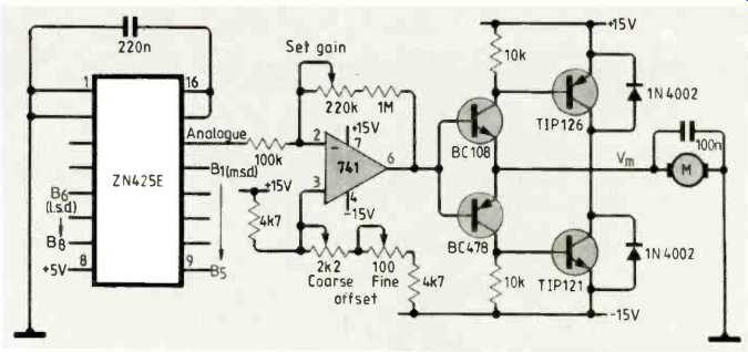
Fig. 2. Bidirectional speed control of a DC motor with split supply rail and
monolithic d-to-a converter. An encoder disc on the motor shaft provides digital
information representing rotational speed for software processing.
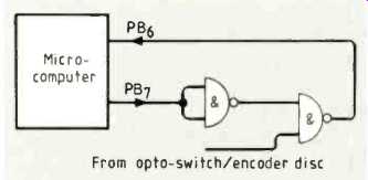
Fig. 3. Pulses from the opto-electronic switch on the encoder disc are gated
through to input PB6 for counting when output PB7 is low. Width of the PB7
pulse is accurately fixed so motor speed can be determined by counting the
number of pulses within the gating period.
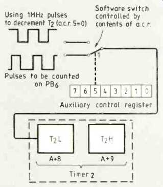
Fig. 4. The v.i.a's second timer has two modes controlled by bit 5 of the
auxiliary control register. When this bit is high, the timer is decremented
each time that input PB6 goes low.
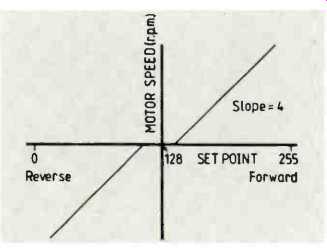
Fig. 5. Relationship between set-point keyboard input and motor speed.
CLOSED-LOOP MOTOR CONTROL
Having established a digital feedback system exists, the loop can be closed to allow the computer to control the motor's speed.
Keyboard input determines the set point, which is processed in line 45 of the routine for closed-loop control, Program 3.
Open-loop motor-amplifier characteristics are shown in Fig.5. If motor load increases, tending to slow it down, drive is increased to the motor by incrementing the bit pattern on the output port, which is done in program line 150. Conversely if the motor tends to speed up, line 170 serves to decrement the port. When the error is zero, nothing is done.
Because the d-to-a converter is chiefly intended for unipolar operation, an output voltage of zero requires a digital input of 128, which is half way up the converter's input range of 0-255. To increase speed in the reverse direction therefore requires decrementing port value X and incrementing it to decrease speed--which is back to front.
Program line 116 takes care of this.
Having constructed the system and successfully executed the algorithm, it is satisfying to produce a mathematical model of the controlled system to give this intuitive design a more rigorous basis.
Try a few experiments. Deliberately intro duce time delay into the system to reduce the sampling rate and note when the system becomes unstable. If the incremental algorithm is too gentle for your needs. why not try bang-bang control? Increase the complexity of the motor by adding mass and damping to the motor shaft. Is the system still well behaved?
If you need more information, try reading Digital Control Systems by Benjamin Kuo (pub. Holt, Rienhart and Winston).
Howard Hutchings is a lecturer at Humber side College of Higher Education. He is also a part time tutor with the Open University.
==========
(adapted from: Wireless World , Dec. 1987)