One of the major problems in the design of electronic organs is the large number of mechanical contacts called for using conventional (discrete component) circuitry. With two manuals of four octaves each, for example, 98 mechanical contacts are needed. This not only complicates construction but could also be a source of trouble in operation. There is often the limitation that each key is only able to play one note. It is desirable for electronic organs to be able to play more than one octave-related note per key, increasing the number of mechanical contacts required by that factor, e.g., 5 x 98 = 490 contacts for the example quoted to be able to play five octave-related notes per key.
A number of integrated circuits have been developed, usually based on digital logic, to overcome such limitations. Many also provide additional features which may be desirable. An example is the (Mullard) TDA1008 which consists of a matrix of gate circuits with eight divide-by-two gates in each circuit. It is a 16-lead dual-in-line plastic package (SOT-38).
One drive input only is required for delivering nine octave-related notes and, by actuating a key input, five successive signals out of the nine can be selected and transferred to the output. Five key inputs are available, each selecting a different combination.
Other features which are available are "sustain" and "percussion" of the output signals; and also "decay" of modulations.
Further simplification of an electronic organ circuit can also be provided by using a top octave synthesizer TOS instead of a series of master oscillators to derive the twelve top octave frequencies required for a "full" organ.
A TOS must be associated with a master oscillator capable of generating a suitable "least common multiple" frequency, with the TOS following it, then providing the twelve highest notes. Used with a suitable gating matrix, further sub-multiples of these notes are obtained, e.g., in the case of the TDA1008 the following output frequencies are available from the five keys, where f is the actual input frequency:
key 1 key 2 key 3 key 4 key 5 output 1 f f/2 f/4 f/8 f/16 output 2 f/2 f/4 f/8 f/16 f/32 output 3 f/4 f/8 f/16 f/32 f/64 output 4 f/8 f/16 f/32 f/64 f/128 output 5 f/16 f/32 f/64 f/128 f/256
This, in effect gives nine different notes available from each of twelve available input frequencies from the TOS, or 96 different notes. Further, operating two or more keys simultaneously will give the sum signal of these frequencies.
MASTER OSCILLATOR
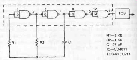
Fig. 1. Master (square-wave) oscillator circuit to feed top octave Synthesizer.
A suitable frequency for the master oscillator is about 4.5 MHz.
A variety of circuits can be used providing they have suitable stability and the necessary amplitude and slew rate for driving the TOS properly. If the master oscillator is a sine wave generator, then it will be necessary to follow this with a Schmitt trigger to obtain the required slew rate. This is not necessary with a square-wave generator and a very simple circuit of this latter type based on the NAND gates contained in the CD4011 integrated circuit is shown in Fig. 1. This requires a stabilized 12-volt supply, as does the TDA1008, so the same supply can be used for both the master oscillator and TDA1008.
The master oscillator output connects to the Top Octave Synthesizer, the tone outputs of which form the input to the TDA1008.
They can be directly connected since the input signal pin of the TDA1008 has an impedance of at least 28 K-O.
GATE MATRIX
Connections to the TDA1008 integrated circuit are shown in Fig. 2. The different levels of supply voltage required are 6 volts, 9 volts and 12 volts, as shown. The five keys can be directly connected, although current-limiting resistors can be used in each key line if necessary.
Five different output frequencies are available at each output Q1, Q2, Q3, Q4, Q5, depending on which key is activated (see table above). To avoid sub-harmonics being generated it is advisable to connect any not-required Q outputs to the + 6 volt supply line.
SUSTAIN
To actuate sustain and percussion effects, a time-delay circuit can be added associated with each key, as shown in Fig. 3. This circuit will sustain the tone(s) for a period after release of the key, but with the resistor also providing a certain delay time. The addition of a series resistor (RS) will delay the build-up of notes, de pending on the RC time constant of this resistor and the associated capacitor in the circuit. Component values given are selected for good tonal response, but this is also a matter of personal preference and so some adjustment of values may be preferred. It is also possible to shorten the decay time of the sustain by adjusting the voltage applied to pin 7. A circuit for doing this is shown in Fig. 4.
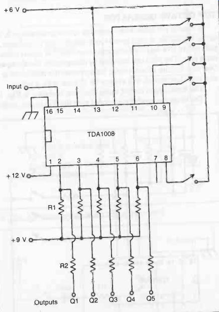
Fig. 2. Basic electronic organ circuit using five keys. Resistors R1 are
all 1-KO. Resistors R2 are all 100 K-O. Q1, Q2, Q3, Q4 and Q5 are the tone
outputs to feed an audio amplifier circuit with loudspeaker.
PERCUSSION
If percussion is required this can be arranged by connecting a capacitor to pin 8 to discharge during keying, associated with a series resistor to give a suitable time constant. Using a 0.47 F capacitor, a suitable series resistor value can be found by experiment.
The decay time is also adjustable via the circuit shown in Fig. 4.
To retain sustain as well, the circuit shown in Fig. 5 should be used. If sustain is wanted, switch S1 is closed and switch S2 opened. C1 then remains charged to sustain the note as long as a key is held down.
Once the key is released the note will decay at the rate established by the decay circuit connected to pin 7. To operate percussion, switch S1 is open and switch S2 closed.
TOP OCTAVE GENERATOR
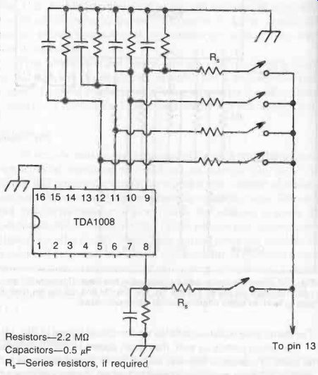
Fig. 3. "Sustain" added to the circuit of Fig. 12-2. Other components
are connected as before.
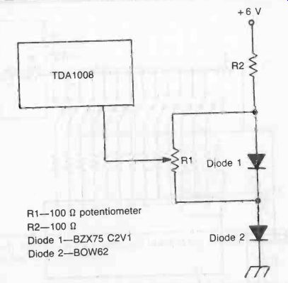
Fig. 4. Adjustable voltage to pin 7 for decay control.
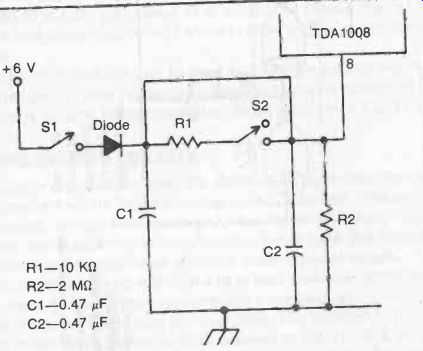
Fig. 5. Percussion circuit with sustain, connecting to pin 8.
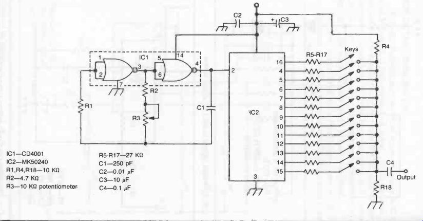
Fig. 6
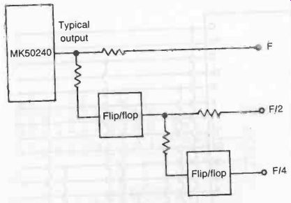
Fig. 7. The range of the organ circuit shown in Fig. 6 can be extended
with flip-flop frequency dividers.
A readily available, easy-to-use top octave generator in IC form is the MK50240. A high speed clock signal is fed to the input, and puts out twelve equally tempered tones (one full octave) plus one extra note. The pitch can be varied by changing the clock frequency.
One nice feature of any circuit built around the MK50240 is that any such instrument will always be in tune with itself.
The basic organ circuit using this chip is shown in Fig. 6.
The range can easily be extended with flip-flop stages, as shown in Fig. 7. Each flip-flop divides the signal by two, or drops it exactly one octave.
More than a single note can be produced at a time. The MK50240 is fully polyphonic.
It is capable of chords. Fig. 8 shows how chords can be hard-wired to allow for one switch operations.
The MK50240 can also be used as a random voltage source.
This is done by lowering the clock frequency to a few hundred Hz, or less. A random voltage generator circuit is shown in Fig. 9.
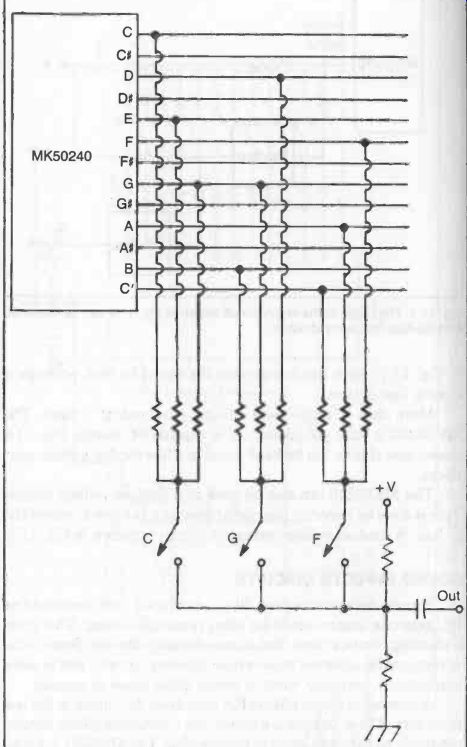
Fig. 8
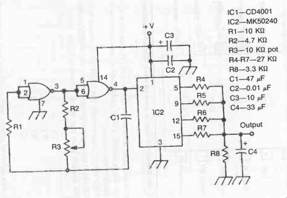
Fig. 9. The MK50240 can also be used as a random voltage source.
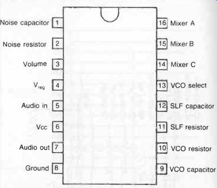
Fig. 10. The SN94281 is used to generate many different sound effects.
SOUND EFFECTS CIRCUITS
Simple electronic organs, like the ones we have described so far, generate square waves (or other rectangle waves). This gives a pleasing, musical tone, but it is undeniably limited. Some tonal variety can be achieved with various filtering circuits. But in some applications, you may want to create other types of sounds.
A number of sound effects ICs have been developed in the last few years. These devices are essentially a complete (albeit simple) electronic sound synthesizer in a single chip. The SN94281 is a typical complex sound generator IC. It is shown in Fig. 10. A block diagram of its internal circuitry is shown in Fig. 11. The sub-circuits can be connected in various ways with a handful of external resistors and capacitors to produce literally thousands of different sounds. Some sounds will be quite musical, and others will be unquestionably non-musical.
A simple circuit built around the SN94281 is shown in Fig. 12. With the following component values, the sounds produced will be like a space laser gun out of a science fiction movie;
C1 = 10 uF
R1 = 1K
R2 = 1.5K
C2 = 0.1 uF
Other very different effects can be achieved with the same circuit, simply by changing the component values. Try these components;
C1 = 0.1 uF
R1 = 1 Meg
R2 = 470K
C2 = 0.001 µF
C1 = 0.1
R1 = 100K
R2 = 220K
C2 = 0.05 p.F
…or almost anything else. Some of the effects are difficult to survive, but they are fascinating to experiment with.
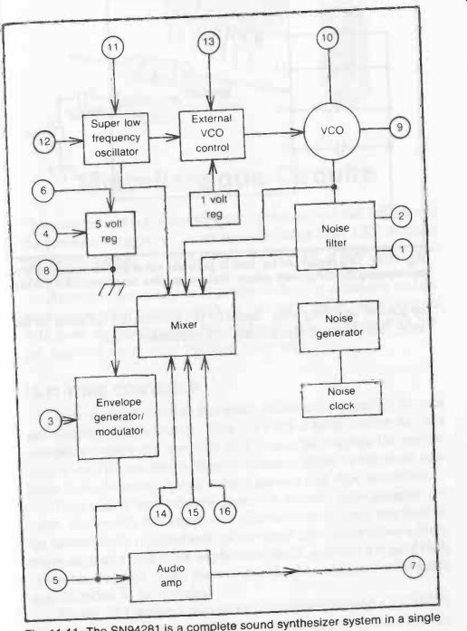
Fig. 11. The SN94281 is a complete sound synthesizer system in a single
IC chip.
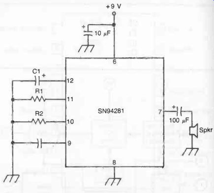
Fig. 12. This circuit can be used to generate many different sound effects
by changing the component values. Some examples are described in the text.