This section covers many IC circuits that do not fall into any of the previous categories. These projects range from LED displays for radio tuning, to intercoms, to infrared transmitters and receivers.
After this final section of projects, there is a section on construction methods which will help you build all of these projects with good, solid techniques that will make your projects work better, and will make your building more enjoyable.
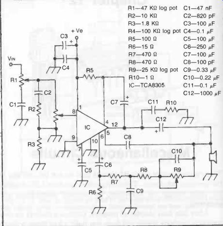
Fig. 1. Hi-Fi tone control circuit suitable for receivers, record players
and tape recorders and characterized by a high input impedance. Potentiometer
R1 is the treble control. Potentiometer R9 is the bass control. Potentiometer
R4 is the volume control.
HI-FI TONE CONTROLS
Tone controls fitted to domestic radios and equivalent circuits are seldom of high quality.
This does not usually matter for AM reception (which can never be Hi-Fi); but can degrade the performance on FM reception.
Similar remarks apply to the tone controls fitted to lower priced record players and tape recorders.
High quality tone controls generally demand quite complex circuits. ICs enable the number of discrete components required to be substantially reduced and, at the same time, offer other advantages such as a high input impedance which matches a typical high impedance source. Tone control can also be combined with audio amplification in IC circuits.
Figure 1 shows a complete circuit based around a TCA8305 integrated circuit incorporating a feedback network which attenuates the low frequencies and boosts the high frequencies. At the same time high frequencies can be attenuated by the treble control potentiometer at the input. The volume control, also on the input side, provides "loudness control" at both high and low frequencies to compensate for the loss of sensitivity of the human ear to such frequencies (i.e., both high and low frequencies tend to sound "less loud" to the ear).
A simpler circuit, using the same IC, is shown in Fig. 2. This has a single tone control potentiometer. The circuit provides flat response at middle frequencies (i.e., around 1 kHz), with marked boost and cut of up to ± 10 decibels at 110 Hz and 10 kHz respectively in the extreme position of the potentiometer.
A (Baxandall) Hi-Fi tone control circuit associated with another type of op-amp is shown in Fig. 3. The IC in this case is the CA3140 BiMOS op-amp.
The tone control circuit is conventional and only a few additional discrete components are required to complete the amplifier circuit around the IC. This circuit is capable of + 15 decibels bass and treble boost and cut at 100 Hz and 10 kHz respectively.
An alternative circuit using the same IC and giving a similar performance is shown in Fig. 4. Both of these circuits require a supply voltage of 30-32 volts. Figure 12-5 shows the same circuit modified for dual supplies.
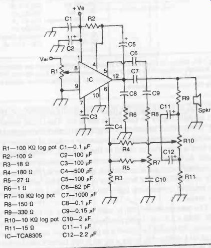
Fig. 2. Alternative Hi-Fi tone control circuit with separate high and low
frequency feedback.
Potentiometer R1 is the volume control. Potentiometer R7 is the treble control and potentiometer R10 the bass control.
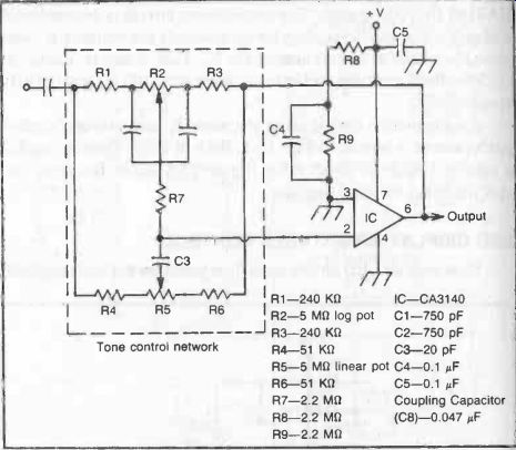
Fig. 3. Simple Hi-Fi tone control circuit. Component values are determined
for a supply voltage of 32 volts. Potentiometer R2 is the bass control. Potentiometer
R5 is the treble control. Components within the dashed outline comprise the
tone control network.
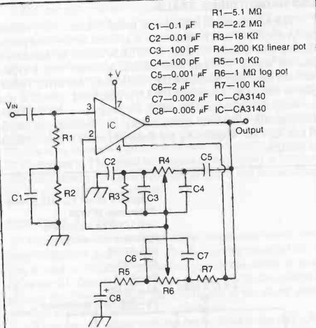
Fig. 4. Another Hi-Fi tone control circuit. Potentiometer R4 is the treble
con trot. Potentiometer R6 is the bass control. Supply voltage is 30 volts.
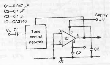
Fig. 5. Tone control for dual supplies.
LED DISPLAY BRIGHTNESS CONTROL
How well an LED shows up is dependent on the ambient light falling on it. In dim light the display is usually quite bright. In direct sunlight it may be difficult to see at all. The circuit shown in Fig. 6 provides an automatic brightness control of a (single) LED by using a silicon photodiode to sense the amount of ambient light and feed a proportional signal to the TCA315 op-amp integrated circuit. As the intensity of light increases the output current from the op-amp increases in proportion, and vice versa, thus automatically compensating the brightness of the LED for artificial light.
The brighter the ambient light, the brighter the LED glows, and vice versa.
The potentiometer (R6) is used for setting up the circuit initially. With a 2.5 volt supply, and with the photodiode in complete darkness, R6 should be adjusted to give a current reading of about 100 µA (0.1 milliamps), using a meter in one battery lead to check.
With this adjustment, and the type of photodiode specified, the LED will then receive an impressed current of 5 mA per 1000 lux illumination of the photodiode.
LED RADIO TUNING SCALE
This simple circuit displays the tuned frequency of a radio in terms of spots of light instead of (or in addition to) the usual pointer moving over a scale. An array of 16 LEDs should be sufficient to indicate station positions with suitable accuracy over a typical medium frequency waveband (i.e., 520 kHz to 1600 kHz). The display is driven by a Siemens UAA170 integrated circuit. A phototransistor is also used to match the brightness of the display automatically to ambient light intensity, i.e., dimming the display in dull light and brightening the display to make it clearly visible in sunlight.
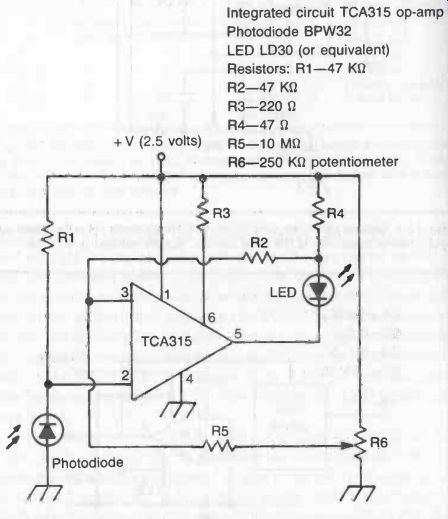
Fig. 6. Circuit for automatic control of brightness of an LED using a photodiode
to sense the level of illumination.
The complete circuit is shown in Fig. 7. The UAA17U is controlled via the voltage divider formed by R1 and R2 supplying the tuning voltage for the AM tuning diode incorporated in the IC.
Since this diode has non-linear characteristics, stations on the left (lower frequency) end of the tuning scale will be more closely concentrated, consistent with station spacing on this broadcast band.
The circuit will work on most normal transistor radio supply voltages (i.e., Vs = 10 to 18 volts), and with an input voltage for frequency indication of Vs = 1.2 to 27 volts using two (Siemens) LD468 LED-arrays. Voltage at the divider point between R1 and R2 should be between 0.06 and 1.16 volts and can be adjusted by R1 if necessary. The actual brightness of the display is automatically controlled by the phototransistor BP101/1, and is also adjustable via the 1 K-o potentiometer.
CAR THIEF ALARM
This is another circuit originated by Siemens and based around their TDB0556A dual timer IC. The first timing circuit of this device is used as a bistable multivibrator with the circuit activated by switch S1. Output level remains at zero, set by the voltage applied to the threshold input pin 2 until one of the alarm contact switches is closed, causing C1 to discharge.
"Press-for-off" alarm switches can be fitted to the doors, bon net and boot lid, so arranged that opening of a door or lid completes that switch contact. This will produce an output signal held for about 8 seconds, pulling in the relay after an initial delay of about 4 seconds. The horn circuit is completed by the relay contacts so the horn will sound for 8 seconds. After this the relay will drop out (shutting off the horn) until capacitor C1 charges up again.
This will take about 3 seconds, when the relay will pull in once more and the horn will sound again. This varying signal of 8 seconds horn on, 3 seconds horn off, will be repeated until switch S1 is turned off (or the battery is flattened).
This type of alarm signal commands more attention than a continuous sounding alarm such as can be given by straightforward on-off electrical switching.
The complete circuit is shown in Fig. 8 with suitable component values, wired in to appropriate points on a car electrical system.
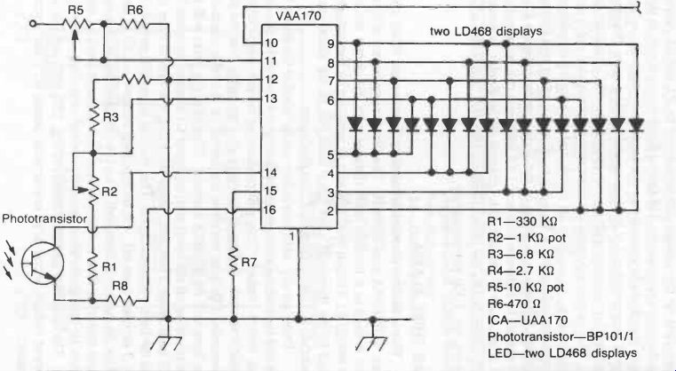
Fig. 7. Sixteen LED display to replace or augment the usual pointer and
scale indication of tuned frequency on an AM radio receiver.
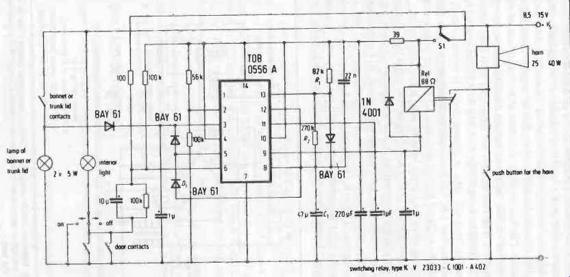
Fig. 8. Circuit design by Siemens for a car theft alarm.
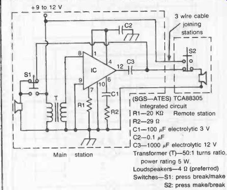
Fig. 9. Intercom circuit using the TCA830S integrated circuit. This IC
is powerful enough to operate fairly large loudspeakers. Component values are
given in the text.
INTERCOM
The TCA830S is a powerful, inexpensive op-amp IC which makes it a particularly attractive choice tor intercoms since the circuit can be built with a minimum number of components. Many other op-amps do not produce the power required for loudspeaker operation without the addition of a further stage of transistor amplification. The basic circuit is contained at the "main" station while the "distant" station merely comprises a loudspeaker and a "calling" switch. The two stations are connected by a 3-wire flex.
The circuit is shown in Fig. 9. The TCA830S requires a heat sink and is fitted with tabs. A printed circuit is recommended, incorporating two 1 in. (25 mm) squares of copper to which the IC tabs can be soldered for the heat sink. Component positioning is not critical since the circuit handles only audio frequencies.
The transformer (T) has a 50:1 turns ratio and is used as a step down transformer between the IC and speaker(s)-also working as a step-up transformer between speaker(s) and IC for working in the reverse mode. In other words the transformer coil with the larger number of turns is connected to pin 8 on the IC. Instead of purchasing this transformer ready-made it can be wound on a stack of standard transformer core laminates 0.35 mm thick, giving a core cross section… ( s.w.g.) and 300 turns of 0.06 mm (46 s.w.g.) enameled copper wire.
The purpose of the transformer is to enable standard 4 to 16-ohm loudspeakers to be used both as microphones and speakers.
These speakers can be of any size, bearing in mind that the maximum power output of the circuit is of the order of 2 watts on a 12-volt supply. The intercom circuit will work on any battery voltage down to 6 volts, 9 or 12 volts being recommended for general operation.
ICE WARNING INDICATOR
This very simple circuit uses a thermistor as a temperature sensor together with three CA3401E op-amps and a minimum of external components. The operating point of the circuit is set by the potentiometer (R2) so that, at an ambient air temperature approaching freezing point, the light emitting diode (LED) starts to flash.
As the temperature falls, the rate of flashing increases until the LED glows continuously once freezing point is reached. Accurate calibration can be carried out in the freezer compartment of a domestic refrigerator with the door open, in conjunction with a thermometer.
The complete circuit is shown in Fig. 10. IC1, IC2 and IC3 are separate op-amp circuits contained in the IC. Thus pins 1 and 6 are the input to IC1 and pin 5 the output of IC1; pins 11 and 12 the input to IC2 and pin 10 the output of 1C2; and pins 2 and 3 the input to IC3 and pin 4 the output of IC3. Pins 8, 9 and 13 are ignored. Pin 7 connects to the earth side of the circuit; and pin 14 to battery plus side.
Layout of this circuit is not critical but all component leads should be kept as short as possible and the LED located some distance away from the integrated circuit. This circuit is powered by a 12 volt battery.
DIGITAL VOLTMETER
A digital voltmeter (known as a DVM) has several advantages over a conventional pointer-and-needle meter, for example:
Easier reading with direct presentation of reading in digits.
Greater accuracy and high speed of reading.
Higher sensitivity.
Greater resolution.
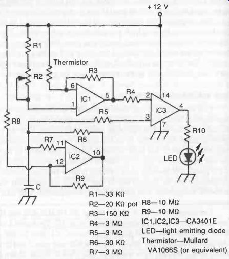
Fig. 10. Circuit for an ice-warning indicator. Adjustment of potentiometer
R2 can set the circuit to flash the LED as air temperature approaches freezing
point, with LED staying permanently alight once freezing temperature is reached.
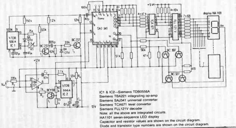
Fig. 11
Unfortunately, the circuitry required for a DVM is quite complicated, making it much more expensive than its simple analog counterpart in the form of a moving coil instrument. However, by using ICs the necessary circuitry for a DVM can be simplified and miniaturized and is within the scope of the amateur to build. The following design by Siemens avoids the use of expensive components and its performance is comparable with that of ready-made DVMs in the medium-price range (well over $100). It has a basic range of up to 9.9 volts with an accuracy of better than 99 percent.
The complete circuit is shown in Fig. 11. The input voltage is converted to a proportional frequency by the op-amp TBA221 connected as an integrating amplifier and the following monostable multivibrator of (IC2). The resulting output pulse is determined by the time constant of R4 and C4 and is of the order of 1.5 As. This pulse turns transistor T1 "on" and "off," the multivibrator thus supplying pulses to the clock input of the counter SAJ341 with a repetition frequency proportional to the input voltage.
These pulses are counted during a measuring interval defined by the other half of the astable multivibrator TDB556A (IC1) with a duty cycle of < 0.5. Its output directly controls the blocking in put of the counter (SAJ341). At the beginning of each measuring interval, 5AJ341 is reset to QA, QB, Qc, QD = L (corresponding to decimal 0) by a short L-pulse applied to the reset input IR. This reset pulse is produced by the measuring-interval generator, the inverting transistor T2 and the following differentiation circuit.
The display, which can be extended to four digits, operates on a time-multiplex basis using a level converter (TCA671), decoder (FLL121V) and display driving transistors BC307 and BC327.
The circuit is set up using a known input voltage (preferably between 2 and 3 volts). Potentiometer R1 is then adjusted to show the correct reading on the display. If this is not possible, then the value of resistor R2 should be changed for the next nearest value up or down, i.e., 270 or 180 kilohms as found appropriate (one value will make matters worse, the other better).
The circuit needs two separate power supplies of + 5 volts at 300 milliamps and- 12 volts at 200 milliamps. For accurate working of the meter both supply voltages should be regulated.
INFRARED TRANSMITTER AND RECEIVER
There are three practical possibilities for remote control signaling: radio (as in model radio control systems); ultrasonics; and light transmission. The latter is the simplest in terms of components and circuitry, especially where simple on/off command only is required. It can be extended to more channels, but at the expense of more complicated circuitry.
Using infrared light transmission it is possible to achieve a range of 100 feet (30 meters) or more quite readily in normal ambient light. Even greater range is possible if the transmitter light beam is focused by a simple lens system. Such infrared remote control systems have become highly practical with the appearance of high-efficiency LEDs with a high infrared transmission and […] was with other remote control systems the basic units involved are a transmitter and receiver.
Single-Channel Infrared Transmitter
This circuit uses the Siemens LD27 improved light-emitting diode LD27 in a pulse modulated transmitter circuit involving the use of two oscillators, a sub-carrier frequency of 50 kHz modulated by a frequency of 10 Hz, the second oscillator having a duty cycle of 250:1. These circuits are based around four CMOS NAND-gates (available in a single IC). The LED is square-wave modulated by a Darlington pair of NPN transistors.
The complete transmitter circuit is shown in Fig. 12 and is quite straightforward. Despite drawing a peak current of 1 amp, the average current drain is only 2 mA with a 6-volt battery sup ply, the peak current actually being supplied from the 470 µF capacitor. This is possible since the 5 kHz output pulse train has a duration of only 400 is in a repetition period of 100 ms.
Single-Channel Infrared Receiver
By comparison, the receiver circuit is more complex since it employs six discrete transistors plus a Darlington pair in addition to three NAND-gates. (See Fig. 13.) The detector is a BPW34 photodiode matched to an input impedance of 80 K-O at 50 kHz.
Signals are received in the form of an infrared pulse train from the transmitter. The receiver circuit following the photodiode amplifies, clips, and rectifies the pulse train signal and applies it to a monostable multivibrator which covers the space between two pulse trains. This means that a dc voltage is available at the output of the receiver as long as the transmitter signal is held on. This receiver output can be used to operate a relay, simple escapement or a signaling light (e.g., a filament bulb or LED).
Since ambient light will introduce a "noise" voltage or interference in the diode, the circuit is intended for narrow band working which operates by placing an infrared filter in front of the photodiode. This can be an infrared photographic filter, or a section of unexposed but developed color film (e.g., Agfa CT18). The transmitter-receiver combination should then work satisfactorily in ambient light intensities up to 10,000 lux with fluorescent light, 4000 in sunlight, or 500 lux maximum in the case of filament lighting.
A simpler receiver circuit is shown in Fig. 14 but will only be suitable for working in dull ambient light (less than 500 lux).
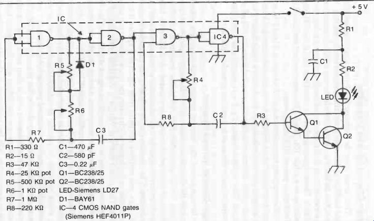
Fig. 12. Design for an infrared transmitter by Siemens.
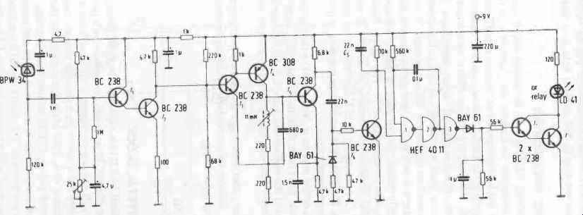
Fig. 13. Design for a matching infrared receiver by Siemens.
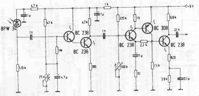
Fig. 14
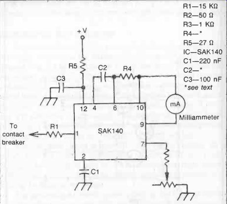
Fig. 15. Electronic rev counter circuit using the SAK140IC.
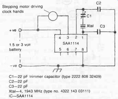
Fig. 16. Crystal controlled clock circuit.
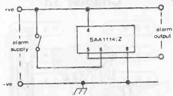
Fig. 17. Additional alarm facility provided in ICSAA1114:Z via pins 5 and
6.
ELECTRONIC REV COUNTER
The (Mullard) SAK140 is an integrated circuit designed as a revolution counter for car engines, etc. Connected to the contact breaker, it is fed by input pulses at "engine speed" rate and converts these pulses into output current pulses of constant duration and amplitude. The output pulse duration is determined by an external resistor-capacitor network. By suitable choice of R and C, the pulse "count" can be indicated on any milliammeter. The circuit will also work on any supply voltage between 10 and 18 volts (e.g., from a car's 12-volt battery) and performance is independent of actual supply voltage (or variation in supply voltage).
The complete circuit is shown in Fig. 15. Resistor R1 is selected so that the input current does not exceed 10 mA (a suitable value for 12-volts supply is 15 K-ohm when typical input current will be 5 mA). The diode acts as a voltage regulator to prevent over loading by large input pulses.
The peak output current is determined by the value of R2 plus R3. This should be at least 50 ohm, the actual value being chosen to suit the range of the milliammeter used. If R2 is made 50 ohm, then R3 can be made 1 K-o, say, and adjusted to suit the range of the milliammeter.
The output pulse duration is determined by the combination of R4 and C2. Suitable values can be found by experiment, the suggested starting point being:
R4-270 K-o
C2-10 nF
QUARTZ CRYSTAL CLOCK
The (Mullard) SAA1114 is a C-MOS integrated circuit designed to work as the "heart" of a crystal controlled clock powered by a single battery. It comprises a master 4 MHz oscillator, a 22-stage frequency divider and a driver for a unipolar stepper motor. With a crystal frequency of 4, 1943 MHz, the output is in the form of a 1 Hz (1 second) pulse of 31.25 milliseconds duration.
A complete clock circuit is shown in Fig. 16 and requires only a few external components. The quartz crystal is a critical component and is associated with a trimmer capacitor C1 for time adjustment. Maximum supply voltage is 3 volts, the circuit drawing a current of about 50 A and supplying a motor output current of about 50 mA.
Another version of this particular IC is also available which incorporates an alarm circuit triggered by an alarm switch operated by the clock hand movement. Output of this alarm from pins 5 to 6 is a 250 Hz tone signal operating for 4 seconds when the alarm is triggered. External connections for this alarm circuit are shown in Fig. 17, the clock motor circuit being as in Fig. 16.