The development of radio circuits around a single IC with the same physical size (and shape) as a single transistor is exemplified by the following. The IC is the Ferranti ZN414 which contains the equivalent of 10 transistors in a complete trf (tuned radio frequency) circuit providing three stages of rf application, a detector and agc (automatic gain control).
The ZN414 has three leads, identified as input, output and ground. It provides a complete radio circuit in itself to be connected to an external tuned circuit, an output decoupling capacitor, a feed back resistor and second decoupling capacitor, and an agc resistor. As with any high gain rf device, certain requirements should be observed to ensure stable and reliable operation. These are:
All leads connecting components to the ICs should be kept as short as possible.
The output decoupling capacitor should be connected with very short leads to the output and ground leads of the ZN414.
The tuned circuit should be kept as far away as possible from the battery and from the loudspeaker and leads connecting these components to the circuit.
The "earthy" side of the tuning capacitor (the moving part) must be connected to the junction of the feedback resistor and the second decoupling capacitor.
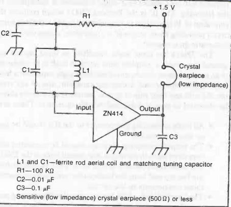
Fig. 1. The ZN414 integrated circuit consists of a preamplifier followed
by three stages of rf amplification and finally a transistor detector. It is
a "complete" radio circuit requiring a minimum of external components
to work.
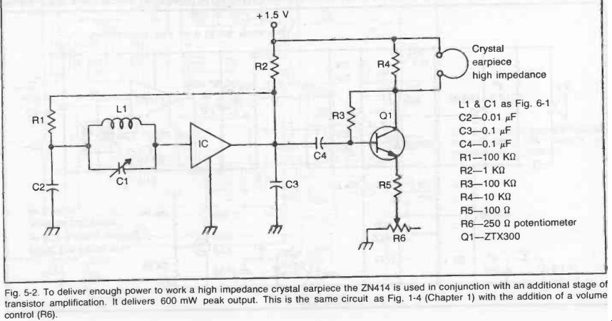
Fig. 2
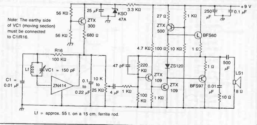
Fig. 3. A high quality receiver circuit based on the ZN414 integrated circuit.
This is a design by Ferranti. Component values are given on the circuit diagram.
A 9-volt battery is used for the supply voltage.
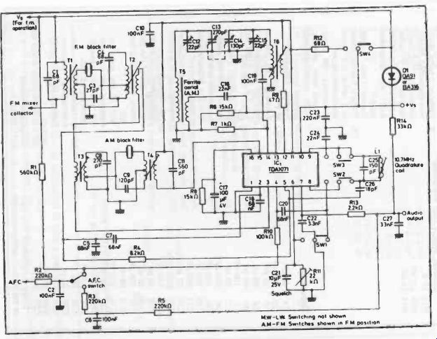
Fig. 4. Circuit diagram of AM/FM receiver using the TDA1071 integrated circuit
(Mullard).

---------- Table 1. Parts for the AM/FM Receiver Circuit.
------------
Resistors
All resistors CR25 10% unless stated R1 560 KO R2 220 KO R3 220 KO R4 8.2 KO R5 220 KO R6 15K4 R7 1 KO R8 15 KO R9 47 0 R10 100 KO R11 22 KO Miniature carbon preset potentiometer, Philips 2322 410 03309 R12 680 R13 2.2 KO R14 33 KO
Capacitors
C1 C2 C3 C4 N5 C6 C7 C8 C9 C10 C11 C12 C13 C14 C15 C16 C17 C18 C19 C20 C21 C22 C23 C24 C25 C26 C27 68 pF 100 nF 27 pF 68 pF 68 nF 100 nF 68 nF 270 pF 120 pF 100 nF 560 pF 22 pF 270 pF 130 pF 22 pF 22 nF 100 µF, 4V 68 nF 100 nF 68 nF 10 ALF, 25 V 3.3 nF 230 nF 22 nF 150 pF 18 pF 3.3 pF
These components form part of the ganged tuning capacitor
Winding data T1
Primary: 12 turns, 0.071 mm enameled copper
Secondary: 2 turns, tapped at 1 turn, 0.071 mm enameled copper
Former: Toko 7P 0092 T2
Primary: 12 turns, tapped at 1 turn, 0.071 mm enameled copper
Secondary: 3 turns, 0.071 mm enameled copper
Former Toko 7P 0092 13
Primary: 3 turns, 0.071 mm enameled copper
Secondary: 120 turns, tapped at 5 turns, wound over primary,
0.071 mm enameled copper
Former: Toko 7P 0089 T4
Primary: 9 turns, tapped at 5 turns, 0.071 mm enameled copper
Secondary: 86 turns, wound over primary, 0.071 mm enameled copper
Former Toko 0089 T5: M.W.
Primary: 78 turns, wound in a single layer, 3 x 3 x 3 x 0.063mm litz
Secondary: 4 turns, wound over the earthy end of the primary 3 x 3 x 3 x 0.063 mm litz L.W.
Primary: 210 turns, wavewound, 9 x 0.063 mm litz
Secondary: 12 turns, wound under the primary, 9 x 0.063 mm litz
For T5 the coils are mounted on a ferrite rod, 178 mm in length, diameter 9.5 mm.
L1 8 turns, 0.071 mm enameled copper.
Former Toko 7P 0092
Switch
SW1 to SW4 4-pole 2-way switch
Integrated circuit IC1 TDA1071
Resistors
All resistors
CR25 10% R1 1.2 KO R2 12 KO R3 27 K0 R4 27 KO R5 12 KO R6 1 K12 R7 39 R8 27 KO R9 121<0 R10 100 0 R11 10 R 1 2 1 kit R 1 3 39
Capacitors C1 18 pF C2 3.3 nF C3 4.7 pF C4 3.3 nF C5 12 pF C6 18 pF C7 3.3 nF C8 18 pF C9 12 pF* C10 3.3 nF C11 2.7 pF C12 5.6 pF C13 3.3 nF C14 56 pF C15 3.3 nF C16 22 nF
Winding data
T1
Primary: 2 turns, 0.031 mm enameled copper
Secondary: 2 turns, 0.031 mm enameled copper
Former: Neosid 5 mm with ferrite core T2
Primary: 4 turns, spaced one diameter 0.71 mm enameled copper
Secondary: 1 turn, interwound with the primary 0.71 mm enameled copper
Former: Neosid 5 mm with ferrite core L1 3 turns, spaced one diameter and tapped at 1 1/2 turns, 0.71 mm enameled copper
Former: Neosid 5 mm with ferrite core
Transistors
TR1, TR2, TR3 BF195
Diode
D1 BB110 "These components form part of the ganged tuning capacitor
---------------
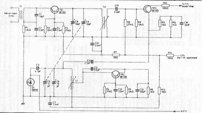
Fig. 5. Front-end circuit for FM operation of the receiver given in Fig. 4 (Mullard).
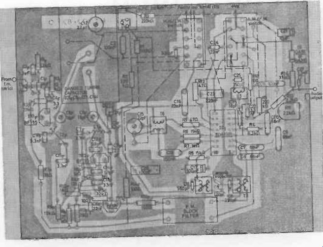
Fig. 6.
Printed circuit layout and component positions for constructing the circuits
of Figs. 4 and 5.
A basic radio circuit using a minimum of components is shown in Fig. 1. L1 and C1 is a conventional tuned circuit, e.g., a high-Q proprietary coil on a ferrite rod with a matching value of tuning capacitor. Alternatively, L1 can be made by winding approximately 80 turns of 0.3 mm diameter (30 swg) enameled copper wire on a ferrite rod 4 cm (1 1/2 in) to 7.5 cm (3 in) long. In this case a matching value of C1 is 150 pF.
This circuit will provide sufficient output power for driving a sensitive low impedance earpiece with an equivalent resistance of approximately 500 ohm. To work a high impedance crystal earpiece an additional stage of amplification is needed. This modified circuit is shown in Fig. 2, requiring four more resistors, a potentiometer, another capacitor and a ZTX300 transistor (or equivalent).
The potentiometer R4 and resistor R5 provide volume control (by adjustment of R4). This can be omitted if the receiver is to be brought down to minimum size, as the directional effects of the ferrite rod aerial will normally provide all the volume control necessary. In that case, replace R4 and R5 with a single 270 ohm resistor.
Fig. 3 shows the circuit extended to give a performancecom parable to that of most domestic portable transistor receivers, driving an 8-0 loudspeaker and powered by a 9-volt battery. This circuit does use six additional transistors and a number of other components, but the component count (and cost) is still substantially less than that of an all-transistor receiver of comparable quality (it is the equivalent of a 16 transistor set).
AM/FM RADIOS
A design for a high performance AM/FM radio receiver is shown in Figs. 5-4 and 5-5. These circuits are by Mullard and are based on their TDA 1071 integrated circuit which incorporates an AM oscillator, an AM mixer with agc, a four-stage differential amplifier and limiter and a four-quadrant multiplier. Both AM and FM functions are combined in the multiplier, giving symmetrical demodulation on AM and quadrative detection with squelch on FM.
Figure 4 shows the AM circuit, working from a ferrite rod aerial. Figure 5-5 shows the circuit for the additional front-end required for FM working, connected to an FM aerial. These circuits will work on any battery voltage from 4.5 volts to 9 volts. For FM operation, the AM-FM switch (SW4) moved to the FM position switches off the AM mixer and oscillator and brings the FM front end circuit into operation. The squelch circuit is separately controlled by SW1, the threshold of squelch operation being set by the potentiometer R11 in Fig. 4.
Component values are given on the two circuit diagrams. A complete list is also given in Tables 1 and 2.
Figure 6 shows a printed circuit layout for the complete circuits of Figs. 5-4 and 5-5, using the components specified. Components with the subscript F are those in the front end circuit (Fig. 5). One additional component is also shown-a 300 pF capacitor adjacent to the medium wave/long wave AM aerial switch, which does not appear on the relevant circuit diagram (Fig. 4).
Note also that this circuit is complete only up to the audio out put stage--i.e., it needs to be followed by an audio amplifier and speaker(s)--see Section 4 for possible circuits to use.