The simplest form of IC multivibrator merely uses an op-amp in a basic oscillator circuit such as that shown in Fig. 1. Oscillation frequency will depend on the IC parameter and the values of the external resistors. The components shown give an output frequency of 1 kHz in the form of a square wave.
The addition of a diode to this circuit, as in Fig. 2, provides a simple pulse generator circuit where the pulse width can be adjusted by using different values for R2. The value of resistor R3 governs the actual pulse duration.
An alternative form of multivibrator is to use two op-amps connected as cross-coupled inverting amplifiers, as shown in Fig. 3.
Here the frequency is established by the time constants of the RC combinations R1-C1 and R2-C2. R1 and R2 should be the same value, and can be anything from 1 KO to 10 KO. C1 and C2 should also be similar values, and anything from 0.01 to 10 µF can be used.
The basic rules governing adjustment and oscillation frequency are that for any particular value of R1 and R2, increasing the value of C1 and C2 will decrease the oscillation frequency, and vice versa.
Similarly, for any particular value of C1 and C2 decreasing the value of R1 and R2 will increase the frequency, and vice versa.
With the component values shown, i.e., R1 = R2 = 8.2 KO and = C2 = 0.2 µF, the oscillation frequency will be 1 kHz.
Decreasing the value of R1 and R2 to 1 KO should result in an oscillation frequency of 10 kHz.
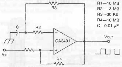
Fig. 1. Simple multivibrator (or square wave oscillator) circuit based on
the CK3401 op-amp. Component values may be chosen to give any specific output frequency required, within limits. These component values give a 1 kHz
square wave output.
A rather more versatile multivibrator circuit is shown in Fig. 4, which has independent controls of "on" and "off" periods. The frequency range is adjustable by choice of capacitor C1 which governs the duration of the square wave pulse generated, viz:
Value of C1 pulse period frequency
1 µF
0.1 µF
0.01 AF
0.00 µF 4 min to 1 sec
0.4 min to 100 min 4 min to 10 min 4 sec to 1 min 250-1 Hz 2500-600 Hz 1500-6000 Hz 15000 kHz-60 kHz
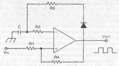
Fig. 2. An almost identical circuit, with the addition of a diode, can be
used as a pulse generator. Here the value of R3 determines the pulse duration
and the value of R2 determines the "off" period.
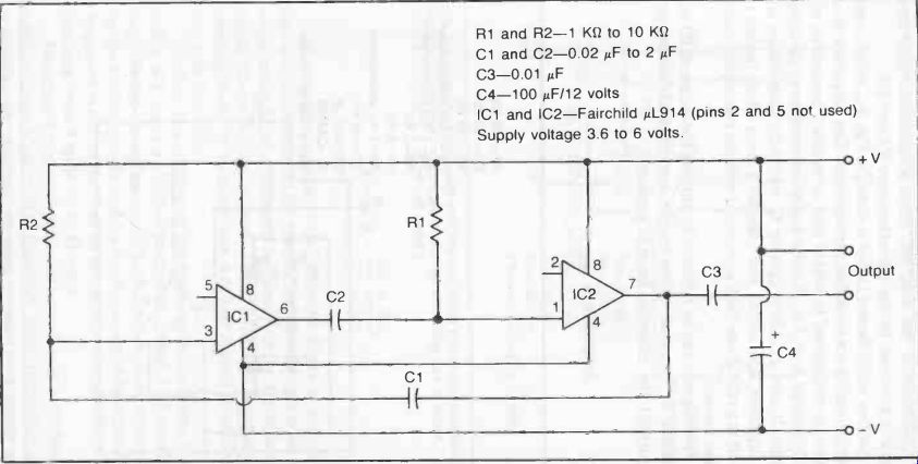
Fig. 3
Adjustment of "on" and "off" times of oscillation within these ranges is governed by the potentiometers R4 and R5.
Another multivibrator circuit is shown in Fig. 5, which is particularly notable for its stable performance. The frequency of oscillation is maintained to within plus or minus 2 percent on any supply voltage from 6 to 15 volts and is independent of the actual voltage. It uses a CA3094 op-amp IC with external resistors and one capacitor. The circuit also includes a lamp which flashes on and off at a rate of one flash per second with the component values given.
Flashing rate can be adjusted by altering the values of R1 and R2 and/or C. To adjust values to give any required flashing rate (frequency), the following formula applies:
frequency 1 2RC1n (2R1/R2 + 1)
R1 R2 where R = R1 + R2
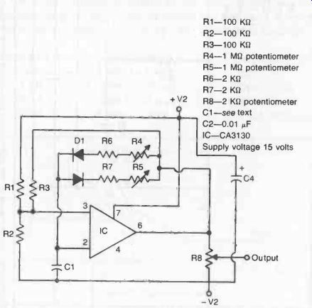
Fig. 4. Multivibrator circuit with adjustable "on" and "off" periods.
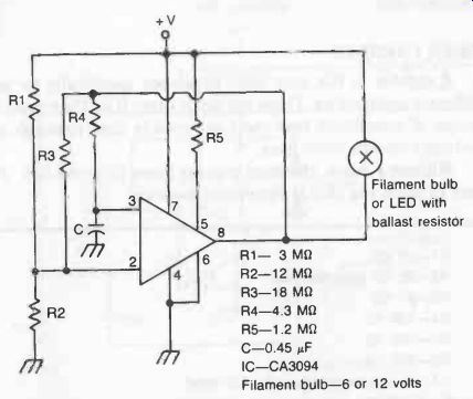
Fig. 5. Astable multivibrator with low frequency of duration to work a flashing
light. Component values given provide a flashing rate of about 1 per second
working off a 6 to 15 volt battery.
In a variation on this circuit shown in Fig. 6, the introduction of a potentiometer R2 enables the pulse length to be varied while maintaining a constant frequency (pulse repetition rate).
Again this circuit can be used to flash a filament lamp, or a light emitting diode. In the latter case, a ballast resistor is needed in series with the LED.
Another straightforward free-running multivibrator is shown in Fig. 7, using a CA3094 integrated circuit. The frequency is controlled by the value selected for R3, and so using a potentiometer for this component enables the frequency to be adjusted. The frequency is also dependent on the supply voltage, which can be anything from 3 volts up to 12 volts.
Designing a multivibrator circuit to work at an audio frequency, while retaining adjustment of frequency, forms the basis of a metronome. The only additional circuitry required is a simple low-power audio amplifier of the kind described in Section 4, connecting to a loudspeaker.
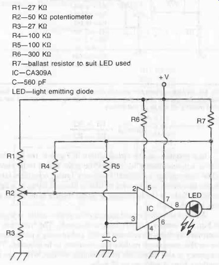
Fig. 6. Adjustable multivibrator circuit, potentiometer R2 varying the pulse
width, or "on" time of the LED indicator. Flashing rate is approximately
1 per second. Supply voltage required for this circuit is 22 to 30 volts.
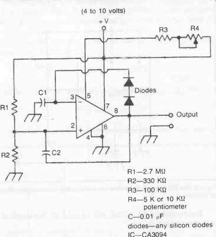
Fig. 7. Free running multivibrator (or pulse generator) circuit, the frequency
of which can be varied by adjustment of the potentiometer R4.
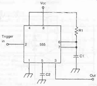
Fig. 8. The 555 timer IC is the heart of many simple monostable multivibrator
circuits.
TIMER CIRCUITS
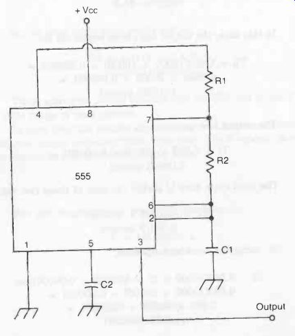
Fig. 9. The 555 timer IC can also be used for astable operation.
A number of ICs have been developed specifically for multivibrator applications. These are called timer ICs. They make the design of monostable (one shot) and astable (free running) multivibrator circuits quite easy.
Without a doubt, the most popular timer IC is the 555. This easy to use 8 pin chip is extremely versatile.
The basic 555 monostable multivibrator circuit is illustrated in Fig. 8. Notice how simple this circuit is--just three external components (two capacitors and a resistor).
Capacitor C2 helps stabilize the circuit. It is not needed in all cases, but it doesn't hurt to include it. A small disc capacitor (0.001 uF to 0.01 p.F) will do the job just fine, and will not add appreciably to the component cost.
The length of the output pulse is determined by R1 and C1.
When a trigger pulse is received, the output goes high for a time equal to;
T = 1.1 R1C1 where T is the time in seconds, R1 is in C2, and C1 is in farads.
For example, if R1 is 220k, and C1 is 0.1µF, the length of the output pulse will be;
T = 1.1 x 220000 x 0.0000001 = 0.0242 second
For practical designs, we will generally need to know the component values for a specific time period. In most cases it is easiest to select a likely value for C1, and then rearrange the equation to solve for R1;
R1 = T/1.1C1
As an example, let's say we need an output pulse of 0.5 second. If we use a 0.5 µF capacitor for C1, we need a resistance of;
R1 = 0.5/(1.1 x 0.0000005) = 0.5/0.00000055 = 909,091 II
A 910 K resistor could be used.
The basic 555 timer astable multivibrator circuit is quite similar. It is shown in Fig. 9. The primary differences are that there is no trigger input, and a second timing resistor (R2) has been added to the circuit.
The time the output is in its high state is determined by both resistors, and capacitor C1;
Th = 0.693(R1 + R2)C1
… while, the output low time is controlled by just R2 and C1;
T1 = 0.693R2C1
Notice that the output high time must always be at least slightly
The total output cycle time is simply the sum of the high and low times;
Tt = Th + T1
If we combine the equations, we get;
Tt = 0.693(R1 + 2R2)C1
Before moving on, let's look at a couple of practical examples.
For our first example, let's assume the following component values;
R1 = 10K R2 = 10K C1 = 1µF
In this case, the output high time works out to;
Th = 0.693(10000 + 10000) x 0.000001 = 0.0693 x 20000 x 0.000001 = 0.01386 second
The output low time is;
T1 = 0.693 x 10000 x 0.000001 = 0.00693 second
The total cycle time is simply the sum of these two values;
Tt = 0.01386 + 0.00693 = 0.02079 second
Or, using the combined equation;
Tt = 0.693(10000 + (2 x 10000)) x 0.000001 = 0.693(10000 + 20000) x 0.000001 = 0.693 x 30000 x 0.000001 = 0.02079 second
Notice that we get the same results in both cases.
[…] nent values;
R1 = 10K R2 = 100K C1 = 50 µF
This time, the high time equals;
Th = 0.693(10000 + 100000) x 0.00005 = 0.693 x 110000 x 0.00005 = 3.8115 seconds
And the low time is;
T1 = 0.693 x 100000 x 0.00005 = 3.465 seconds
So the total cycle time works out to;
Tt = 3.8115 + 3.465 = 7.2765 seconds
These examples clearly indicate that the 555 can be used for a wide range of time periods.
In most practical astable applications, we are more concerned with the output frequency than cycle time.
The frequency is simply the reciprocal of the total cycle time;
F = 1/Tt For our two examples, we get frequencies of;
F = 1/0.02079 = 48 Hz. (appx.) and;
F = 1/72.765 = 0.0137 Hz. (appx.)
Notice that larger cycle times result in lower frequencies.
We can calculate the frequency directly by using this formula;
F = 1.44/((R1 + 2R2)C1)
As an example, let's consider the following component values;
R1 = 22K R2 = 33K C1 = 0.01 µFs Here, the output frequency works out to approximately;
F = 1.44/((22000 + (2 x 33000)) x 0.00000001) = 1.44/((22000 + 66000) x 0.00000001) = 1.44/(88000 x 0.00000001) = 1.44/0.00088 = 1636 Hz.
In most practical applications, we will need to find the component values that will provide the desired output frequency. There are two approaches you could take.
The first approach would be to select the resistor values first for the desired duty cycle, then rearrange the equation to solve for C1;
C1 = 1.44/((R1 + 2R2) x F)
For example, let's say we need a 100 Hz signal with a 1:3 duty cycle. The duty cycle ratio is;
R2 : R1 + R2 R2, by definition, is equal to 1 in the ratio. We simply select a likely value- say, 10K, then factor the duty cycle ratio;
1 : 3 lr : Xr + lr
In this example, R1 should be twice the value of R2, or 20K.
If we assume our application is not overly critical, we can simply use the nearest standard resistance value, which is 22K.
Now, we just plug the values into the rearranges frequency equation;
C1 = 1.44/((10000 + (2 x 22000)) x 100) = 1.44/((10000 + 44000) x 100) = 1.44/(54000 x 100) = 1.44/5400000 = 0.00000027 farad = 0.27 µF
A 0.25 µF, or a 0.3 µF capacitor would probably do, but in some applications you will need some rather oddball capacitance values.
You can usually make do with series and/or parallel combinations of standard capacitance values.
The other method of solving for component values is to select a likely value for C1, then solve for the lumped resistance R, which is equal to (R1 + 2R2). This time the equation looks like this;
R = 1.44/(C1 x
Again we will assume we need a 100 Hz output with a 1:3 duty cycle. For the time being, we will ignore the duty cycle, and just solve for R.
A 0.1 µF capacitor would be a reasonable choice, so;
R = 1.44/(0.0000001 x 100) = 1.44/0.00001 = 144,000 ohm
Now we know that;
R = 144,000 = R1 + 2R2
The next step is to factor the duty cycle as described above.
For a 1:3 duty cycle, R1 should be twice the value of R2, so we can easily find the value of R2;
R = 144000 = R1 + 2R2 =
2R2 + 2R2 =
4R2 R2 = 144000/4 = 36000 SI
K1 is simply twice the value of R2, so;
R1 = 2R2 =
2 x 36000 =
72000 ohm
These aren't standard resistance values. You could use parallel/series combinations of standard resistance values, or you could use trimpots for R1 and R2.
If your application is not too critical you could round the values off. For example, you could use a 33K resistor for R2 and a 68K resistor for R1. The actual output frequency would work out to;
F = 1.44/((68000 + (2 x 33000)) x 0.0000001) =
1.444(68000 + 66000) x 0.0000001) =
1.44/(134000 x 0.0000001) =
1.44/0.0134 =
107 Hz.
That's pretty close to the desired frequency of 100 Hz. Component tolerances could create that much error, so the rounding off effect is minimal, except in very critical applications using low tolerance components.
PROGRAMMABLE TIMERS
555 timer circuits are ideal for many monostable and astable timing applications in which fixed timing periods are required. however, they aren't so suitable for applications in which the timing period must be changed, or when multiple time periods are simultaneously required.
The timing resistor in a monostable circuit could be replaced with a potentiometer. Also, several timing capacitors could be selected via a switch to set the operating range.
Variable frequency astable circuits have additional problems.
One or both of the timing resistors could be replaced with potentiometers, but unless both resistances are changed in exact unison, the duty cycle will vary as the frequency is changed. Switch selectable timing capacitors could be used, but this is still a bit awkward.
The solution is a programmable timer, such as the XR-2240.
The pin-out diagram for this powerful and versatile IC is shown in Fig. 10. This chip has eight outputs in a binary weighted scheme.
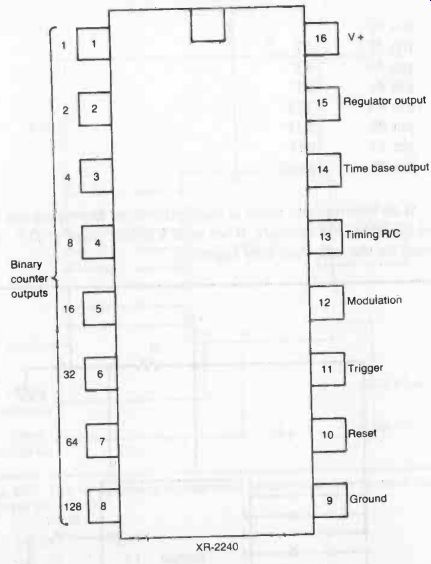
Fig. 10. The XR-2240 is a programmable timer integrated circuit.
The basic timing period is determined by a single resistor and capacitor. The formula is as simple as it can possibly be- even simpler than the one for the 555 timer;
T = RC
A timing pulse equal to T is available at pin #1. A timing pulse twice the basic timing period (2T) is brought out to pin #2. The output at pin #3 has twice the timing period of pin #2 (4T).
This pattern is continued to pin #8, with each pin outputting a timing period twice that of its predecessor; pin #1 pin #2 2T pin #3 4T pin #4 8T pin #5 16T pin #6 32T pin #7 64T pin #8 128T If an intermediate value is required, two or more pins can be tied together. For example, if we need a timing pulse of 21T, we would tie the following pins together;
pin #5 16T
pin #3 4T
pin #1 1T
total 21T
The basic monostable circuit built around the XR-2240 is shown in Fig. 11.
The astable circuit, shown in Fig. 12, is quite similar.
In either circuit, a string of 8 DIP switches can be used to select any time value from 1T to 255T.
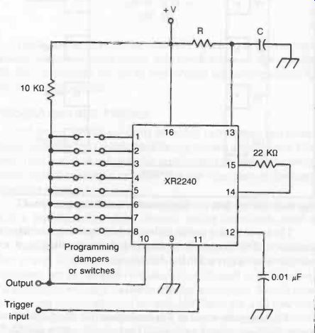
Fig. 11. This is the basic programmable monostable multivibrator circuit
built around the XR2240.
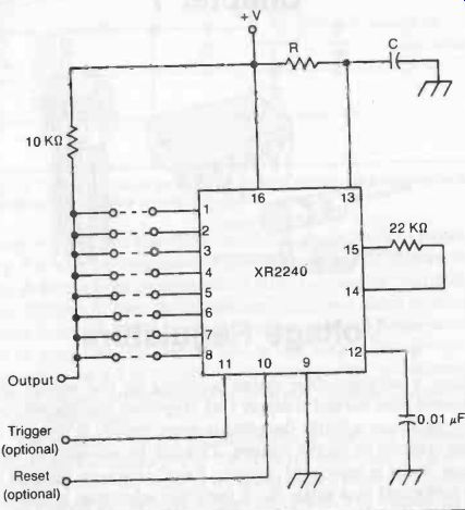
Fig. 12. This is the basic programmable astable multivibrator circuit built
around the XR-2240.