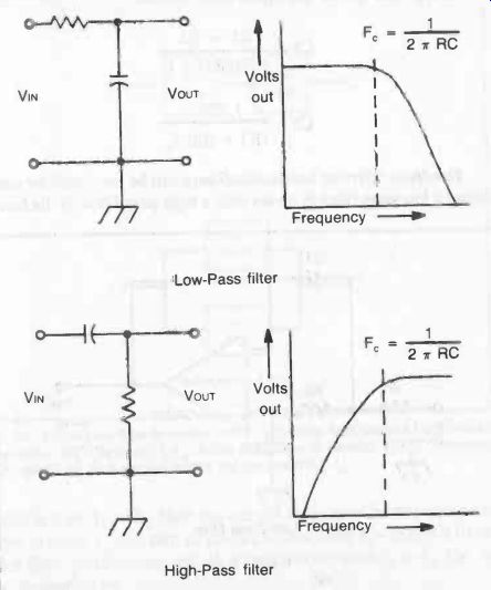
Fig. 1. Basic filters are provided by a combination of resistor (R) and
capacitor (C). A low pass filter attenuates frequencies above the critical
frequency (f0). A high pass filter attenuates frequencies below fc.
A basic filter circuit consists of a combination of a resistor and a capacitor. This combination of R and C has a time constant which defines the cut-off frequency of the filter; but the actual mode of working also depends on the configuration of the two components (see Fig. 1.) With R in series and C across the circuit, frequencies lower than the cut-off frequency are passed without attenuation.
Frequencies at above the cut-off frequency are then sharply attenuated. This is called a low-pass filter.
With C in series and R across the circuit, frequencies above the cut-off frequency are passed without attenuations. Frequencies be low the cut-off frequency are then sharply attenuated. This is called a high-pass filter. Practical circuits for these two types of filter are shown in Fig. 2.
The amount of attenuation provided by a filter is expressed by the ratio volts out/volts in, or voltage ratio. This is quoted in decibels (dB) -- a 3dB drop being equivalent to a voltage ratio drop from 1.0 to 0.707, or a power loss of 50 percent.
Op-amps can be used as practical filters associated with an external capacitor, with the advantage that the more sophisticated circuitry involved can provide superior performance to straight-forward RC combinations.
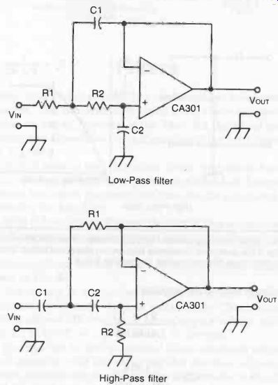
Fig. 2. Basic low-pass and high-pass filter circuits incorporating an op-amp
for better performance.
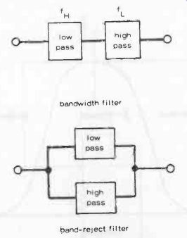
Fig.
3. A low-pass filter in series with a high-pass filter passes frequencies only
within the bandwidth fcfH. A low-pass filter in parallel with a high-pass filter
rejects all frequencies within the bandwidth fL-fH.
Two filter circuits based on the CA301 op-amp are shown in Fig. 2. In the case of the low-pass filter component values are calculated from these formulas:
C1- R1 + R2 1.414R1R2f, 1.414 C2- (R1 + R2) fc
... where fc is the effective cut-off point.
In the case of the high-pass filter circuit:
C1 R1 + R2 1.732R1R2 fc 1.732 C2 = (R1 + R2) fc
Bandpass filters or bandwidth filters can be produced by combining a low-pass filter in series with a high-pass filter. If the band-width is from fL to fH, then the cut-off frequency for the low-pass filter is made fH and that of the high-pass filter fL--Fig. 3 (top).
This filter combination will pass frequencies from 1L to 1H, i.e., in the desired band.
To produce a band-reject filter, a low-pass filter is used in parallel with a high-pass filter, as in the second diagram. This combi nation will reject all frequencies within the band fL to fH.
Bandpass and band-reject filters are essentially functional mirror images of each other, as illustrated in the frequency response graphs of Fig. 4. For convenience, we will confine our discussion to the bandpass filter.
This type of filter has two cut-off frequencies-the upper cut off and the lower cut-off. The action of the filter can not be de scribed with a single specification as the low-pass and high-pass filters can.
Usually the cut-off frequencies are not identified specifically in describing bandpass filters. Instead, we identify the mid-point between the two cut-off frequencies.
This is called the center frequency, for obvious reasons.
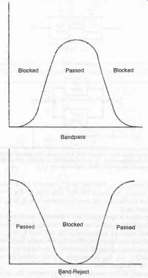
Fig. 4. Band pass and band-reject filters are functional mirror images of
each other.
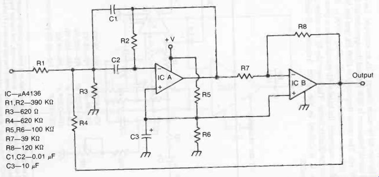
Fig. 5.
But we still need another specification to indicate how far apart the cut-off frequencies are. This specification is generally given in one of two forms. The most direct is the bandwidth specification.
This is simply the frequency distance from the lower cut-off to the upper cut-off.
This can all be made clearer with an example. Let's say the lower cut-off frequency is 3000 Hz, and the upper cut-off frequency is 5000 Hz. The center frequency is 4000 Hz, and the bandwidth is the difference between the cut-offs (5000- 3000 = 2000 Hz).
More commonly, the bandwidth specification is given in terms of Q, or the Quality factor. The lower the Q, the wider the bandwidth. Q is defined as the center frequency divided by the bandwidth:
Q = Fc / BW
or, for our example:
Q = 4000 / 2000 = 2
A typical bandpass filter circuit is shown in Fig. 5. Using the component values specified, the center frequency will be about 1000 Hz.
Some practical band-reject (or notch) filter circuits are shown in Figs. 6 and 7.
There is one final type of filter of interest which we should look at before moving on. The state variable filter has multiple outputs for the various filter types described in the last few pages. A fairly typical state variable filter circuit is shown in Fig. 8. For the component values shown the Q is 3.4, and the cut-off frequencies for the low-pass and high-pass sections is 3000 Hz. This is also the center frequency for the bandpass section. The notch frequency is 9,500 Hz.
Fig. 9 shows another state variable filter circuit. In this one the high-pass and low-pass cut-off frequencies are adjustable from 300 Hz to 3000 Hz. The potentiometers should have a reverse log type taper.
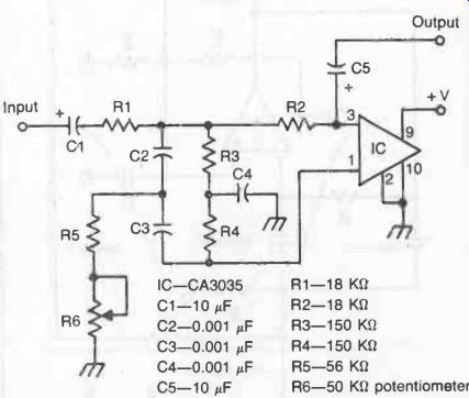
Fig. 6. A notch filter rejects input signals at a specific center frequency
but passes all other frequencies. This is a working circuit, the center frequency
being determined by the value of components in the two networks R3-R4-R5-R6:
and C2-C3-C4. The actual "sharpness" of rejection or notch width
is adjustable via potentiometer R6. Component values for a 1 kHz center frequency
are given in the figure.
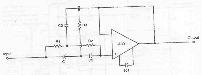
Fig. 7
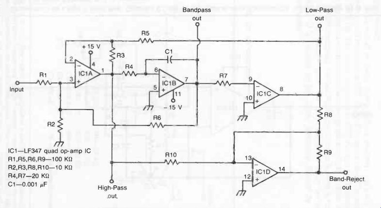
Fig. 8. A state variable filter features multiple filtering outputs.
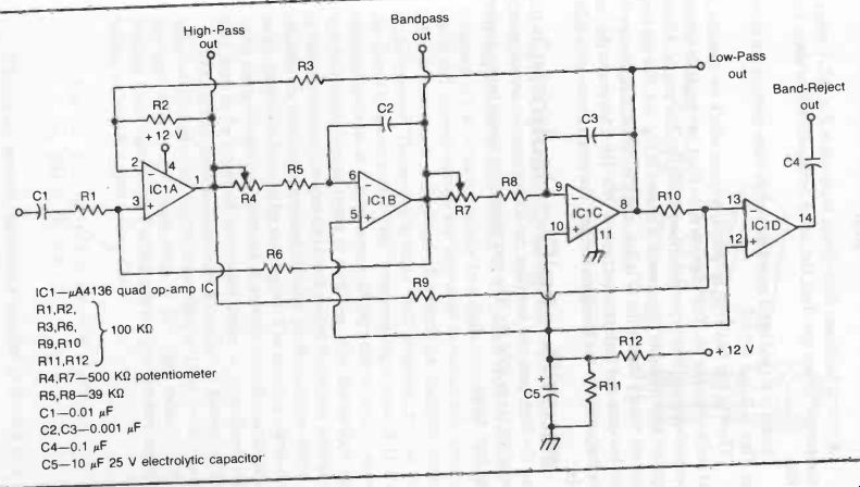
Fig. 9. Another state variable filter circuit.