AMAZON multi-meters discounts AMAZON oscilloscope discounts
Objectives
This Section will help you understand and become familiar with other sensors that play a very important part in process control, but may not be encountered on a daily basis. The following are covered in this Section:
_ Position, distance, velocity, and acceleration sensors
_ Rotation sensors using light and Hall effect sensors
_ Force, torque, load cells, and balances
_ Smoke detectors, gas, and chemical sensors in industry
_ Sound and light measurements
_ Sound and optical devices
1. Introduction
There are many sensors other than level, pressure, flow, and temperature that may not be encountered on a day to day basis-such as position, force, smoke, and chemical sensors-but play an equally important part in process control in today's high-technology industries and/or for operator protection. These sensors will not be discussed in as much detail as the sensors already discussed. However, the student should be aware of their existence and operation.
2. Position and Motion Sensing
2.1 Basic position definitions
Many industrial processes require both linear and angular position and motion measurements. These are required in robotics, rolling mills, machining operations, numerically controlled tool applications, and conveyers. In some applications it is also necessary to measure speed, acceleration, and vibration. Some transducers use position sensing devices to convert temperature and/or pressure into electrical units and controllers can use position sensing devices to monitor the position of an adjustable valve for feedback control.
Absolute position is the distance measured with respect to a fixed reference point and can be measured whenever power is applied.
Incremental position is a measure of the change in position and is not referenced to a fixed point. If power is interrupted, the incremental position change is lost. An additional position reference such as a limit switch is usually used with this type of sensor. This type of sensing can give very accurate positioning of one component with respect to another and is used when making master plates for tooling and the like.
Rectilinear motion is measured by the distance traversed in a given time, velocity when moving at a constant speed, or acceleration when the speed is changing in a straight line.
Angular position is a measurement of the change in position of a point about a fixed axis measured in degrees or radians, where one complete rotation is 360° or 2p radians. The degrees of rotation of a shaft can be absolute or incremental. These types of sensors are also used in rotating equipment to measure rotation speed as well as shaft position and to measure torque displacement.
Arc-minute is an angular displacement of 1/60 of a degree.
Angular motion is a measure of the rate of rotation. Angular velocity is a measure of the rate of rotation when rotating at a constant speed about a fixed point or angular acceleration when the rotational speed is changing.
Velocity or speed is the rate of change of position. This can be a linear measurement, i.e., feet per second (ft/s), meters per second (m/s), and so forth, or angular measurement, i.e., degrees per second, radians per second, rate per minute (r/m), and so forth.
Acceleration is the rate of change of speed, i.e., feet per second squared (ft/s^2 ), meters per second squared (m/s^2 ), and the like for linear motion, or degrees per second squared, radians per second squared, and the like, in the case of rotational motion.
Vibration is a measure of the periodic motion about a fixed reference point or the shaking that can occur in a process due to sudden pressure changes, shock, or unbalanced loading in rotational equipment. Peak accelerations of 100 g can occur during vibrations which can lead to fracture or self destruction. Vibration sensors are used to monitor the bearings in heavy rollers such as those used in rolling mills; excessive vibration indicates failure in the bearings or damage to rotating parts that can then be replaced before serious damage occurs.
Potentiometers are a convenient method of converting the displacement in a sensor to an electrical variable. The wiper or slider arm of a linear potentiometer can be mechanically connected to the moving section of a sensor. Where rotation is involved, a single or multiturn (up to 10 turns) rotational type of potentiometer can be used. For stability, wire-wound devices should be used, but in environmentally-unfriendly conditions, lifetime of the potentiometer may be limited by dirt, contamination, and wear.
Linear variable differential transformers (LVDT) are devices that are used for measuring small distances and are an alternative to the potentiometer. The device consists of a primary coil with two secondary windings one on either side of the primary. (see FIG. 1a). A movable core when centrally placed in the primary will give equal coupling to each of the secondary coils. When an ac voltage is applied to the primary, equal voltages will be obtained from the secondary windings which are wired in series opposition to give zero output voltage, as shown in FIG. 1b. When the core is slightly displaced an output voltage proportional to the displacement will be obtained. These devices are not as cost effective as potentiometers but have the advantage of being noncontact. The outputs are electrically isolated, accurate, and have better longevity than potentiometers.
Light interference lasers are used for very accurate incremental position measurements. Monochromatic light (single frequency) can be generated with a laser and collimated into a narrow beam. The beam is reflected by a mirror attached to the moving object which generates interference fringes with the incident light as it moves. The fringes can be counted as the mirror moves. The wave length of the light generated by a laser is about 5 × 10^-7 m, so relative positioning--to this accuracy over a distance of 1/2 to 1 m is achievable.
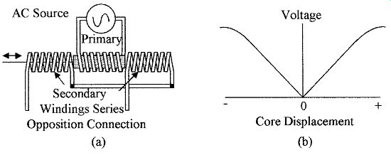
FIG. 1 Demonstrated is (a) the LVDT with a movable core and three
windings and (b) the secondary voltage versus core displacement for the
connections shown.
Ultrasonic, infrared, laser, and microwave devices can be used for distance measurement. The time for a pulse of energy to travel to an object and be reflected back to a receiver is measured, from which the distance can be calculated, i.e., the speed of ultrasonic waves is 340 m/s and the speed of light and microwaves is 3 × 10^8 m/s. Ultrasonic waves can be used to measure distances from 1 to about 50 m, whereas the light and microwaves are used to measure longer distances.
If an object is in motion the Doppler effect can be used to determine its speed. The Doppler effect is the change in frequency of the reflected waves caused by the motion of the object. The difference in frequency between the transmitted and reflected signal can be used to calculate the velocity of the object.
Hall effect sensors detect changes in magnetic field strength and are used as a close proximity protector. The Hall effect occurs in semiconductor devices and is shown in FIG. 2a. Without a magnetic field the current flows directly through the semiconductor plate and the Hall voltage is zero. Under the influence of a magnet field, as shown, the current path in the semiconductor plate becomes curved, giving a Hall voltage between the sides adjacent to the input/output current. In FIG. 2b a Hall effect device is used to detect the rotation of a cog wheel. As the cogs move pass the Hall device, the strength of the magnetic field is greatly enhanced causing an increase in the Hall voltage. The device can be used to measure linear as well as rotational position or speed and can also be used as a limit switch.
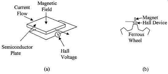
FIG. 2 Shown is a semiconductor plate used as (a) Hall effect device
and (b) application of a Hall effect device for measuring the speed and
position of a cog wheel.
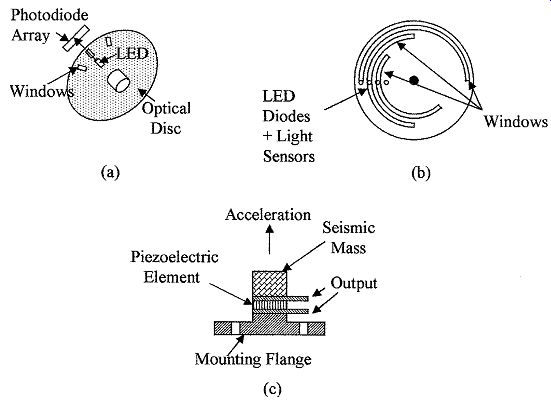
FIG. 3 Shows (a) an incremental optical disc, (b) an absolute position
optical discs, and (c) a piezoelectric accelerometer.
Magneto-resistive element (MRE) is an alterative to the Hall effect device. In the case of the MRE its resistance changes with magnetic field strength.
Optical devices detect motion by sensing the presence or absence of light.
FIG. 3 shows two types of optical discs used in rotational sensing. FIG. 3a shows an incremental optical shaft encoder. Light from the light-emitting diode (LED) shines through windows in the disc on to an array of photodiodes. As the shaft turns, the position of the image moves along the array of diodes. At the end of the array, the image of the next slot is at the start of the array. The relative position of the wheel with respect to its previous location can be obtained by counting the number of photodiodes traversed and multiplying them by the number of slots monitored. The diode array enhances the accuracy of the position of the slots, i.e., the resolution of the sensor is 360° divided by the number of slots in the disc divided by the number of diodes in the array. The slots can also be replaced by reflective strips, in which case the light from the LED is reflected back to a photodiode array.
Only one slot in the disc is required to measure rate per minute. FIG. 3b shows an absolute position encoder. An array of LEDs (one for each window) with a corresponding photo detector for each window can give the position of the wheel at any time. Only three windows are shown in the figure, for greater accuracy more slots would be used. The pattern shown on the disc is for the gray code.
Other patterns may be used on the disc such as the binary code.
Optical devices have many uses in industry other than for the measurement of the position and speed of rotating equipment. Optical devices are used for counting objects on conveyer belts on a production line, measurement and control of the speed of a conveyer belt, location and position of objects on a conveyer, location of registration marks for alignment, bar code reading, measurement and thickness control, and detecting for breaks in filaments and so forth.
Power lasers can also be included with optical devices as they are used for scribing and machining of metals, laminates, and the like.
Accelerometers sense speed changes by measuring the force produced by the change in velocity of a known mass (seismic mass), see Eq. (1). These devices can be made with a cantilevered mass and a strain gauge for force measurement or can use capacitive measurement techniques. Accelerometers are now commercially available, made using micromachining techniques. The devices can be as small as 500 µm × 500 µm, so that the effective loading by the accelerometer on a measurement is very small. The device is a small cantilevered seismic mass that uses capacitive changes to monitor the position of the mass. Piezoelectric devices similar to the one shown in FIG. 3c are also used to measure acceleration. The seismic mass produces a force on the piezoelectric element during acceleration which causes a voltage to be developed across the element. Accelerometers are used in industry for the measurement of changes in velocity of moving equipment, in the automotive industry as crash sensors for air bag deployment, and in shipping crates where battery operated recorders are used to measure shock during the shipment of expensive and fragile equipment.
Vibration sensors typically use acceleration devices to measure vibration.
Micromachined accelerometers make good vibration sensors for frequencies up to about 1 kHz. Piezoelectric devices make good vibration sensors with an excel lent high-frequency response for frequencies up to 100 kHz. These devices have very low mass so that the damping effect is minimal. Vibration sensors are used for the measurement of vibration in bearings of heavy equipment and pressure lines.
2.3 Position application consideration
Optical position sensors require clean operating conditions and in dirty or environmentally-unfriendly applications they are being replaced by Hall or MRE devices in both rotational and linear applications. These devices are small, sealed, and rugged with very high longevity and will operate correctly in fluids, in a dirty environment, or in contaminated areas.
Optical devices can be used for reading bar codes on containers and imaging.
Sensors in remote locations can be powered by solar cells that fall into the light sensor category.
3. Force, Torque, and Load Cells
3.1 Basic definitions of force and torque
Many applications in industry require the measurement of force or load. Force is a vector and acts in a straight line, it can be through the center of a mass, or be offset from the center of the mass to produce a torque, or with two forces a couple. Force can be measured with devices such as strain gages. In other applications where a load or weight is required to be measured the sensor can be a load cell.
Mass is a measure of the quantity of material in a given volume of an object.
Force is a term that relates the mass of an object to its acceleration and acts through its center of mass, such as the force required to accelerate a mass at a given rate. Forces are defined by magnitude and direction and are given by the following:
Force (F ) = mass (m) × acceleration (a) (1)
Torque occurs when a force acting on a body tends to cause the body to rotate and is defined by the magnitude of the force times the perpendicular distance from the line of action of the force to the center of rotation (see FIG. 4a).
Units of torque are pounds (lb), feet (ft), or newton meter (N·m). Torque is some times referred to as the moment of the force, and is given by
Torque (t) = F × d (3)
A couple occurs when two parallel forces of equal amplitude, but in opposite directions, are acting on an object to cause rotation, as shown in FIG. 4b and is given by the following equation:
Couple (c) = F × d (4)
3.2 Force and torque measuring devices
Force and weight can be measured by comparison as in a lever-type balance which is an ON/OFF system. A spring balance or load cell can be used to generate an electrical signal that is required in most industrial applications.
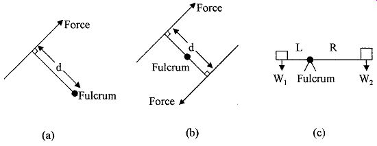
FIG. 4 Types of forces shown are (a) torque, (b) couple, and (c) balanced
forces.
Analytical or lever balance is a device that is simple and accurate, and operates on the principle of torque comparison. FIG. 4c shows a diagram of a balance. When in balance the torque on one side of the fulcrum is equal to the torque on the other side of the fulcrum, from which we get the following:
W1 × L = W2 × R (5)
where W1 is a weight at a distance L from the fulcrum and W2 the counter balancing weight at a distance R from the fulcrum.
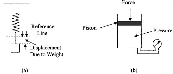
FIG. 5 Force measuring devices (a) spring balance and (b) using pressure
to measure force.
Spring transducer is a device that measures weight by measuring the deflection of a spring when a weight is applied, as shown in FIG. 5a. The deflection of the spring is proportional to the weight applied (provided the spring is not stressed), according to the following equation:
F = Kd (6)
where F = force in pounds or newtons
K = spring constant in pounds per inch or newtons per meter
d = spring deflection in inches or meters
Hydraulic and pneumatic devices can be used to measure force. This can be done by monitoring the pressure in a cylinder when the force (pounds or newtons) is applied to a piston as shown in FIG. 5b, the relation between force (F) and pressure ( p) is given by:
F = pA (7)
... where A is the area of the piston.
Piezoelectric devices, as previously noted, produce an electrical charge between the opposite faces of a crystal when the crystal is deformed by a force that makes them suitable for use as a force sensor (see FIG. 3c). Many crystals exhibit the piezoelectric effect. Some common crystals are as follows:
- Quartz
- Rochelle salt
- Lithium sulphate
- Tourmaline
Quartz devices have good sensitivity but have high output impedance. The output voltage drifts under low loading due to noise and temperature effects, but is well suited for measuring rapidly changing forces as well as static forces.
Tensile and compressive forces are measured with strain gauges; a strain gauge can use a piezoresistive material or other types of material that changes their resistance under strain. FIG. 6a shows the use of a strain gauge to measure the strain in a solid body under stress from a tensile force, in this case the material under tension elongates and narrows. Strain gauges, as shown, are used to measure stress in a material from which the properties of the material can be calculated. A strain gauge can be used to measure stress from compressive forces as shown in FIG. 6b. An object under compressive forces will shorten and fatten and the strain can be measured.
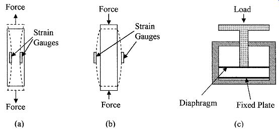
FIG. 6 Examples of (a) a solid object under tensile strain, (b) a
solid body under compression, and (c) a capacitive load cell.
Weight measurements are made with load cells which can be capacitive, electromagnetic, use piezoelectric elements, or strain gauges. A capacitive load cell is shown in FIG. 6c. The capacitance is measured between a fixed plate and a diaphragm. The diaphragm moves towards the fixed plate when force or pres sure is applied, giving a capacitive change proportional to the force.
Dynamometer is a device that uses the twist or bending in a shaft due to torque to measure force. One such device is the torque wrench used to tighten bolts to a set level, which can be required in some valve housing. The allowable torque for correct assembly will be given in the manufacturer's specification. The twist in a shaft from a motor can be used to measure the torque output from the motor.
3.3 Force and torque application considerations
In most applications compensation should be made for temperature effects. Electrical transducers can be compensated by using them in a bridge circuit with a compensating device in the adjacent arm of the bridge. Changes in material characteristics due to temperature changes can be compensated using temperature sensors and applying a correction factor to the measurement. Vibration can also be a problem when measuring force, but this can usually be corrected by damping the movement of the measuring system.
4. Smoke and Chemical Sensors
The detection of smoke, radiation, and chemicals is of great importance in industrial processing not only as it relates to the safety of humans and the control of environment pollution both atmospheric and ground, but is also used in process control applications to detect the presence, absence, or levels of impurities in processing chemicals.
Smoke detectors and heat sensors (automatic sprinklers) are now common place in industry for the protection of people, equipment, and monitoring and control of chemical reactions. Low-cost smoke detectors using infrared sensing or ionization chambers are commercially available. Many industrial processes use a variety of gases in processing-such as inert gases (nitrogen)-to prevent contamination from oxygen in the air, or conversely, gases or chemicals can be introduced to give a desired reaction. It is therefore necessary to be able to monitor, measure, and control a wide variety of gases and chemicals. A wide variety of gas and chemical sensors are available. Of these, the Taguchi-type of sensor is one of the more common types of sensors.
4.1 Smoke and chemical measuring devices
Infrared sensors detect changes in the signal received from a light emitting diode due to the presence of smoke in the light path or the presence of an object in the light path.
Ionization chambers are devices that detect the leakage current between two plates that have a voltage between them. The leakage occurs when carbon particles from smoke are present and provide a conductive path between the plates.
Taguchi-type sensors are used for the detection of hydrocarbon gases, such as carbon monoxide and dioxide, methane, and propane. The Taguchi sensor has an element coated with an oxide of tin that combines with hydrocarbon to give a change in electrical resistance which can be detected. Periodically the element is heated and the chemical reaction is reversed, reducing the coating back to tin oxide. Likewise, the sensing process can be repeated. The tin oxide can be made sensitive to different hydrocarbons by using different oxides of tin, different deposition techniques, and so on.
4.2 Smoke and chemical application consideration
Many hazardous, corrosive, toxic, and environmentally-unfriendly chemicals are used in the processing industry. These chemicals require careful monitoring during use, transportation, and handling. In a basic text it is not possible to cover the above-mentioned sensors' availability and precautions in their applications, but just to make the student aware of their existence. Analysis labs and control rooms must meet code; further information can be obtained from the ISA series RP 60 practices. All processing plants and labs will have an alarm system which can shut down certain operations if a problem occurs. These systems are regularly tested and are often duplicated to provide built-in fail-safe features such as redundancy as protection against sensor failure.
5. Sound and Light
5.1 Sound and light formulas
The measurement of sound and light is important as it relates to the sense of hearing and sight, as well as many industrial applications such as the use of sound waves for the detection of flaws in solids and in location and linear distance measurement. Sound pressure waves can induce mechanical vibration and hence failure. Excessive sound levels produce noise pollution. Light and its measurement is used in many industrial applications for high-accuracy linear measurements, location of overheating (infrared), object location and position measurements, photo processing, scanning, readers (bar codes), and so forth.
Sound waves are pressure waves that travel through air, gas, solids, and liquids, but cannot travel through space or a vacuum unlike radio (electromagnetic) waves.
Pressure waves can have frequencies up to about 50 kHz. Sound or sonic waves start at 16 Hz and go up to 20 kHz; above 30 kHz sound waves are ultrasonic. Sound waves travel through air at about 340 m/s (depends on temperature, pressure, and the like.). The amplitude or loudness of sound is measured in phons.
Sound pressure levels (SPL) are units often used in the measurement of sound levels and are defined as the difference in pressure between the maximum pres sure at a point and the average pressure at that point. The units of pressure are normally expressed as follows:
1 dyn/cm^2 = 1 ubar = 1.45 ×10^-5 psi (8)
where 1 N = 10^5 dyn.
Decibel (dB) is a logarithmic measure used to measure and compare amplitudes and power levels in electrical units, sound, light, and the like. The sensitivity of the ears and eyes are logarithmic. To compare different sound intensities the following applies:
Sound level ratio in dB = (9)
where I1 and I2
are the sound intensities at two different locations and are scalar units. A reference level (for I2) is 10^-16 W/cm^2
(average level of sound that can be detected by the human ear at 1 kHz) to measure sound levels.
When comparing different pressure levels the following is used:
Pressure level ratio in dB = (10)
where P1 and P2 are the pressures at two different locations (note pressure is a measure of sound power, hence 20 log). For P2, 20 µN/m^2 is accepted as the average pressure level of sound that can be detected by the human ear at 1 kHz and is therefore, the reference level for measuring sound pressures.
Typical figures for SPL are as follows:
Threshold of pain 140 to 150 dB
Rocket engines 170 to 180 dB
Factory 80 to 100 dB
Light is ultra-high frequency electromagnetic wave that travels at 3 × 10^8 m/s.
Light amplitude is measured in foot-candles (fc) or lux (lx). The wavelength of visible light is from 4 to 7 × 10^-7m. Longer wavelengths of electromagnetic waves are termed infrared and shorter wavelengths, ultraviolet. Light wavelengths are sometimes expressed in terms of angstroms (Å) where 1 Å =
Intensity is the brightness of light. The unit of measurement of light intensity in the English system is the foot-candle (fc), which is one lumen per square foot (lm/ft^2 ). In the SI system the unit is the lux (lx) which is one lumen per square meter (lm/m^2 ). The phot (ph) is also used and is defined as one lumen per square centimeter (lm/cm^2 ). The lumen replaces the candela (cd) in the SI system. The dB is also used for the comparison of light intensity as follows:
Light level ratio in dB = (11)
where F1 and F2 are the light intensity at two different points.
The change in intensity levels for both sound and light from a source is given by the following equation:
Change in levels = (12)
where d1 and d2 are the distances from the source to the points being considered.
e mentioned at this point as they are used in the process control industry and are also electromagnetic waves. X-rays are used primarily as inspection tools; the rays can be sensed by some light-sensing cells and can be very hazardous if proper precautions are not taken.
5.2 Sound and light measuring devices
Microphones are transducers used to convert sound levels into electrical signals, i.e., electromagnetic, capacitance, ribbon, crystal, carbon, and piezoelectric microphones can be used. The electrical signals can then be analyzed in a spectrum analyzer for the various frequencies contained in the sounds or just to measure amplitude.
Sound level meter is the term given to any of the variety of meters for measuring and analyzing sounds.
Photocells are used for the detection and conversion of light intensity into electrical signals. Photocells can be classified as photovoltaic, photoconductive, photoemissive, and semiconductor.
Photovoltaic cells develop an emf in the presence of light. Copper oxide and selenium are examples of photovoltaic materials. A microammeter calibrated in lux (lm/m^2 ) is connected across the cells and measures the current output.
Photoconductive devices change their resistance with light intensity. Such materials are selenium, zirconium oxide, aluminum oxide, and cadmium sulfide.
Photoemissive materials, such as mixtures of rare earth elements (cesium oxide), liberate electrons in the presence of light.
Semiconductors are photosensitive and are commercially available as photodiodes and phototransistors. Light generates hole-electron pairs, which causes leak age in reversed biased diodes and base current in phototransistors. Commercial high-resolution optical sensors are available with the electronics integrated onto a single die to give temperature compensation and a linear voltage output with incident light intensity are also commercially available. Such a device is the TSL 250.
Also commercially available are infrared (IR) light-to-voltage converters (TSL 260) and light-to-frequency converters (TSL 230). Note, the TSL family is manufactured by Texas Instruments.
5.3 Light sources
Incandescent light is produced by electrically heating a resistive filament or the burning of certain combustible materials. A large portion of the energy emitted is in the infrared spectrum as well as the visible spectrum.
Atomic-type sources cover gas discharge devices such as neon and fluorescent lights.
Laser emissions are obtained by excitation of the atoms of certain elements.
Semiconductor diodes (LED) are the most common commercially available light sources used in industry. When forward biased, the diodes emit light in the visible or IR region. Certain semiconductor diodes emit a narrow band of wave length of visible rays; the color is determined by material and doping. A list of LEDs and their color is given in Table 1.
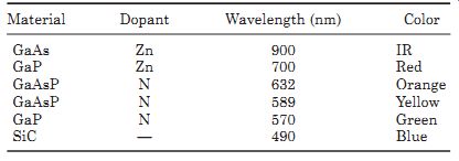
Table 1 LED Characteristics
5.4 Sound and light application considerations
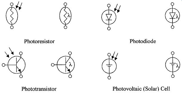
FIG. 7 Schematic symbols for opto sensors.
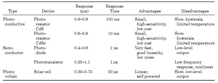
Table 2 Summary of Opto Sensor Characteristics
Selection of sensors for the measurement of sound and light intensity will depend on the application. In instrumentation a uniform sensitivity over a wide frequency range requires low inherent noise levels, consistent sensitivity with life, and a means of screening out unwanted noise and light from other sources.
In some applications, such as the sensing of an optical disc, it is only necessary to detect absence or presence of a signal, which enables the use of cheap and simple sensors. For light detection, the phototransistor is being used very widely, because of the ability with integrated circuits to put temperature correction and amplification in the same package for high-sensitivity. The device is cost effective and has good longevity.
FIG. 7 shows the schematic symbols used for optoelectronic sensors and Table 2 gives a comparison of photosensor characteristics.
Summary
A number of different types of sensors were discussed in this Section. Sensors for measuring position, speed, and acceleration were introduced. The concepts of force, torque, and load measurements were discussed together with measuring devices. Also covered in this Section were smoke and chemical sensors and an introduction to sound and light measurements and instruments.
The salient points covered are as follows:
1. The basic terms and standards used in linear and rotational measurements and the sensors used for the measurement of absolute and incremental position, velocity, and acceleration
2. Optical and magnetic sensors and their use as position measuring devices in linear as well as rotational applications and sensors used for distance measurement
3. Definitions of force, torque, couples, and load and the use of mechanical forces in weight measurements
4. Stress in materials, the use of strain gauges for its measurement, and instruments used for measurement
5. Smoke and chemical sensors were introduced with sensors and applications
6. An introduction to sound and light units and the units used in their measurement with examples
7. Sound and optical sensing devices are given and the type of semiconductor devices used for light generation with their color spectrum
Problems
1 What force is necessary to accelerate a mass of 17 lb at 21 ft/s^2?
2 What is the acceleration of 81 kg, when acted upon by a force of 55 N?
3 What torque does a force of 33 lb produce 13 ft perpendicular from a fulcrum?
4 What force is required to produce a torque of 11 N·m, if the force is 13 m from the fulcrum?
5 A couple of 53 N·m is produced by two equal forces of 15 N, how far are they apart?
6 A couple of 38 lb-ft is produced by two equal forces 8 ft apart. What is the magnitude of the forces?
7 A balance has a reference weight of 10 kg, 0.5 m from the fulcrum. How far from the fulcrum must a weight of 16 kg be placed to be balanced?
8 A reference weight of 15 lb is placed 2 ft from the fulcrum to balance a weight 4.7 ft from the fulcrum. What is the weight?
9 A spring balance has a spring constant of 3 lb/in, a basket with 6-lb potatoes extends the spring 2.7 in. What is the weight of the basket?
10 A spring balance has a spring constant of 2.3 N/m. What is the deflection of the balance when it is loaded with 0.73 N?
11 A force of 10 N is applied to a piston 150 cm in diameter in a closed cylinder. What is the pressure in the cylinder?
12 What force is applied to a 9.2-in piston in a cylinder, if the pressure in the cylinder is 23 psi?
13 What is the wavelength of 13 kHz sound waves?
14 What is the frequency of radar waves whose wavelength is 2.5 cm?
15 A person is 375 m from a bell and a second person is 125 m from the bell. What is the difference in the sound levels of the bell rings heard by the two people?
16 What is the sound pressure level corresponding to 67 dB?
17 The light intensity 20 ft from a light bulb is 3.83 dB higher than at a second point. What is the distance of the second point from the bulb?
18 What is the change in light intensity when the distance from the light source is increased from 35 to 85 ft?
19 What is the angular displacement that can be sensed by an angular displacement sensor, if the circular disc on a shaft has 115 slots and the photodiode array has 16 diodes? See FIG. 3.
20 The rotational speed of a steel cog wheel is being sensed with a magnetic sensor. If the wheel has 63 teeth and is rotating at 1021 r/min, what is the frequency of the output pulses?
Related Articles -- Top of Page -- Home