AMAZON multi-meters discounts AMAZON oscilloscope discounts
Objectives
This Section will introduce you to humidity, density, viscosity, and pH, and help you understand the units used in their measurement. This Section will also familiarize you with standard definitions in use, and the instruments used for their measurement.
The salient points covered in this Section are as follows:
_ Humidity ratio, relative humidity, dew point, and its measurement
_ Understanding and use of a psychrometric chart
_ Instruments for measuring humidity
_ Understand the difference between density, specific weight, and specific gravity
_ Instruments for measuring density and specific gravity
_ Definition of viscosity and measuring instruments
_ Defining and measuring pH values
1. Introduction
Many industrial processes such as textiles, wood, chemical processing and the like, are very sensitive to humidity; consequently it is necessary to control the amount of water vapor present in these processes. This Section discusses four physical parameters.
They are as follows:
1. Humidity
2. Density, specific weight, and specific gravity
3. Viscosity
4. pH values
2. Humidity
2.1 Humidity definitions
Humidity is a measure of the relative amount of water vapor present in the air or a gas. Relative humidity (F) is the percentage of water vapor by weight present in a given volume of air or gas compared to the weight of water vapor present in the same volume of air or gas saturated with water vapor, at the same temperature and pressure, i.e.,
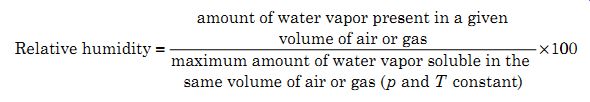
(1)
(2)
The term saturated means the maximum amount of water vapor that can be dissolved or absorbed by a gas or air at a given pressure and temperature. If there is any reduction of the temperature in saturated air or gas, water will con dense out in the form of droplets, i.e., similar to mirrors steaming up when taking a shower.
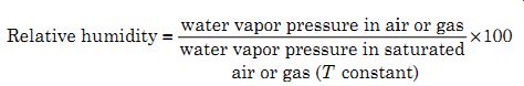
Specific humidity, humidity ratio, or absolute humidity can be defined as the mass of water vapor in a mixture in grains (where 7000 grains = 1 lb) divided by the mass of dry air or gas in the mixture in pounds. The measurement units could also be in grams.
(3)

(4)

(5)
where P (water vapor) is pressure and P (air or gas) is a partial pressure. The conversion factor between mass and pressure is 0.622.
Example 1 Examples of water vapor in the atmosphere are as follows: Dark storm clouds (cumulonimbus) can contain 10 g/m^3 of water vapor.
Medium density clouds (cumulus congestus) can contain 0.8 g/m^3 of water vapor.
Light rain clouds (cumulus) contain 0.2 g/m^3 of water vapor.
Wispy clouds (cirrus) contain 0.1 g/m^3 of water vapor.
In the case of the dark storm clouds this equates to 100,000 tons of water vapor per square mile for a 10,000 ft tall cloud.
Dew point is the temperature at which condensation of the water vapor in air or a gas will take place as it is cooled at constant pressure, i.e., it is the temperature at which the mixture becomes saturated and the mixture can no longer dissolve or hold all of the water vapor it contains. The water vapor will now start to condense out of the mixture to form dew or a layer of water on the surface of objects present.
Dry-bulb temperature is the temperature of a room or mixture of water vapor and air (gas) as measured by a thermometer whose sensing element is dry.
Wet-bulb temperature is the temperature of the air (gas) as sensed by a moist element. Air is circulated around the element causing vaporization to take place; the heat required for vaporization (latent heat of vaporization) cools the moisture around the element, reducing its temperature.
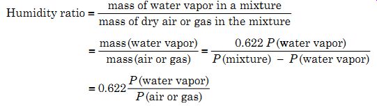
Psychrometric chart is a somewhat complex combination of several simple graphs showing the relation between dry-bulb temperatures, wet-bulb temperatures, relative humidity, water vapor pressure, weight of water vapor per pound of dry air, BTUs per pound of dry air, and so on. While it may be a good engineering reference tool, it tends to overwhelm the student. For example Fig. 1 shows a psychrometric chart from Heat Pipe Technology, Inc. for standard atmospheric pressure; for other atmospheric pressures the sets of lines will be displaced.
To understand the various relationships in the chart it is necessary to break the chart down into only the lines required for a specific relationship.
Example 2 To obtain the relative humidity from the wet and dry bulb temperatures, the three lines shown in Fig. 2a should be used. These lines show the wet and dry bulb temperatures and the relative humidity lines. For instance, if the dry and wet bulb temperatures are measured as 76°F and 57°F, respectively, which when applied to Fig. 1 shows the two temperature lines as intersecting on the 30 percent relative humidity line, hence, the relative humidity is 30 percent. When the wet and dry bulb temperatures do not fall on a relative humidity line a judgment call has to be made for the value of the relative humidity.
FIG. 1 Psychrometric chart for air-water vapor mixtures. (Courtesy
of Heat Pipe Technology, Inc)
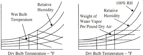
FIG. 2 Lines required for finding (a) the relative humidity and (b)
the condensation temperature.
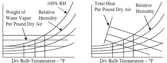
FIG. 3 Lines required finding (a) the weight of water vapor and (b)
the heating requirements.
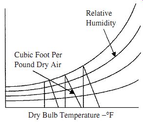
FIG. 4 Lines required finding the volume per pound of dry air.
Example 3 If the temperature in a room is 75°F and the relative humidity is 55 percent, how far can the room temperature drop before condensation takes place? Assume no other changes. In this case it is necessary to get the intersection of the dry bulb temperature and relative humidity lines, as shown in Fig. 2b and then the corresponding horizontal line (weight of water vapor per pound of dry air). Using Fig. 1 the intersection falls on 0.01 lb of moisture per pound of dry air, because the weight of water vapor per pound of dry air will not change as the temperature changes.
This horizontal line can be followed across to the left until it reaches the 100 percent relative humidity line (dew point). The temperature where these lines cross is the temperature where dew will start to form, i.e., 57°F. The wet and dry bulb temperatures are the same at this point. Note that in some charts the weight of water vapor in dry air is measured in grains, where 1 lb = 7000 grains or 1 grain = 0.002285 oz.
Example 4 This example compares the weight of water vapor in air at different humidity levels. The question is, how much more moisture does air at 80°F and 50 percent relative humidity contain than air at 60°F and 30 percent relative humidity? Using Fig. 3a as a reference, it is necessary to get the intersection of the dry bulb temperature and the relative humidity lines. The horizontal line where they intersect gives the weight of water vapor per pound of dry air as in the previous example. Using Fig. 1 the intersections are 0.0108 and 0.0032 lb, hence, the difference = 0.0076 lb or 53 grains.
Example 5 How much heat is required to raise the temperature of air at 50°F and 75 percent relative humidity to 75°F and 45 percent relative humidity? Referring to Fig. 3b, the intersection of the dry bulb temperature and relative humidity lines must be found, and hence, the total dry heat line passing through the intersection (these lines are an extension of the wet bulb temperature lines to the total heat per pound dry air scale). From Fig. 1 the intersection of the temperature and relative humidity lines fall on 18.2 and 27.2 Btus/lb of dry air, giving a difference of 9.0 Btus/lb of dry air.
Example 6 In air at 75°F and 45 percent relative humidity, how much space is occupied by a pound of dry air? The lines shown in Fig. 4 are used. The intersection of the dry bulb temperature and relative humidity lines on the cubic feet per pound of dry air line gives the space occupied by 1 lb of dry air. From Fig. 1 the lines intersect at 13.65 ft^3 giving this as the volume containing 1 lb of dry air.
2.2 Humidity measuring devices
Hygrometers. Devices that indirectly measure humidity by sensing changes in physical or electrical properties in materials due to their moisture content are called hygrometers. Materials such as hair, skin, membranes, and thin strips of wood change their length as they absorb water. The change in length is directly related to the humidity. Such devices are used to measure relative humidity from 20 to 90 percent, with accuracies of about ±5 percent. Their operating temperature range is limited to less than 70°C.
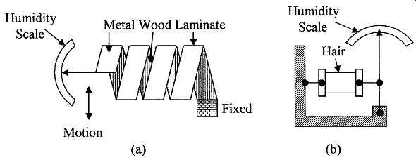
FIG. 5 Two types of hygrometers using (a) metal/wood laminate and (b)
hair.
Laminate hygrometer is made by attaching thin strips of wood to thin metal strips forming a laminate. The laminate is formed into a helix as shown in Fig. 5a, as the humidity changes the helix flexes due to the change in the length of the wood. One end of the helix is anchored, the other is attached to a pointer (similar to a bimetallic strip used in temperature measurements); the scale is graduated in percent humidity.
Hair hygrometer is the simplest and oldest type of hygrometer. It is made using hair as shown in Fig. 5b. Human hair lengthens by 3 percent when the humidity changes from 0 to 100 percent, the change in length can be used to control a pointer for visual readings or a transducer such as a linear variable differential transformers (LVDT) for an electrical output. The hair hygrometer has an accuracy of about 5 percent for the humidity range 20 to 90 percent over the temperature range 5 to 40°C.
Resistive hygrometer or resistive humidity sensors consist of two electrodes with interdigitated fingers on an insulating substrate as shown in Fig. 6a. The electrodes are coated with a hydroscopic material (one that absorbs water such as lithium chloride). The hydroscopic material provides a conductive path between the electrodes; the coefficient of resistance of the path is inversely proportional to humidity. Alternatively, the electrodes can be coated with a bulk polymer film that releases ions in proportion to the relative humidity; temperature FIG. 6 Methods of measuring humidity (a) electrical using electrodes with inter-digitated fingers covered with a hydroscopic material and (b) sling psychrometer.
Correction can again be applied for an accuracy of 2 percent over the operating temperature range 40 to 70°C and relative humidity from 2 to 98 percent. An ac volt age is normally used with this type of device, i.e., at 1 kHz a relative humidity change from 2 to 98 percent will typically give a resistance change from 10 M? to 1 k?. Variations of this device are the electrolytic and the resistance-capacitance hygrometer.
Capacitive hygrometer. The dielectric constant of certain thin polymer films changes linearly with humidity, so that the capacitance between two plates using the polymer as the dielectric is directly proportional to humidity. The capacitive device has good longevity, a working temperature range of 0 to 100°C, a fast response time, and can be temperature compensated to give an accuracy of ±0.5 percent over the full humidity range.
Piezoelectric or sorption hygrometers use two piezoelectric crystal oscillators; one is used as a reference and is enclosed in a dry atmosphere, and the other is exposed to the humidity to be measured. Moisture increases the mass of the crystal which decreases its resonant frequency. By comparing the frequencies of the two oscillators, the humidity can be calculated. Moisture content of gases from 1 to 25,000 ppm can be measured.
Psychrometers. A psychrometer uses the latent heat of vaporization to determine the relative humidity. If the temperature of air is measured with a dry bulb thermometer and a wet bulb thermometer, the two temperatures can be used with a psychrometric chart to obtain the relative humidity, water vapor pressure, heat content, and weight of water vapor in the air. Water evaporates from the wet bulb trying to saturate the surrounding air. The energy needed for the water to evaporate cools the thermometer, so that the dryer the day, the more water evaporates and, hence, the lower the temperature of the wet bulb.
To prevent the air surrounding the wet bulb from saturating, there should be some air movement around the wet bulb. This can be achieved with a small fan or by using a sling psychrometer, which is a frame holding both the dry and wet thermometers that can rotate about a handle as shown in Fig. 6b. The thermometers are rotated for 15 to 20 s. The wet bulb temperature is taken as soon as rotation stops before it can change, and then the dry bulb temperature is taken (which does not change).
Dew point measuring devices. A simple method of measuring the humidity is to obtain the dew point. This is achieved by cooling the air or gas until water condenses on an object and then measuring the temperature at which condensation takes place. Typically, a mirrored surface, polished stainless steel, or silvered surface is cooled from the back side, by cold water, refrigeration, or Peltier cooling. As the temperature drops, a point is reached where dew from the air or gas starts to form on the mirror surface. The condensation is detected by the reflection of a beam of light by the mirror to a photocell. The intensity of the reflected light reduces as condensation takes place and the temperature of the mirror at that point can be measured.
Moisture content measuring devices. Moisture content of materials is very important in some processes. There are two methods commonly used to measure the moisture content; these are with the use of microwaves or by measuring the reflectance of the material to infrared rays.
Microwave absorption by water vapor is a method used to measure the humidity in a material. Microwaves (1 to 100 GHz) are absorbed by the water vapor in the material. The relative amplitudes of the transmitted and microwaves passing through a material are measured. The ratio of these amplitudes is a measure of the humidity content of the material.
Infrared absorption uses infrared rays instead of microwaves. The two methods are similar. In the case of infrared, the measurements are based on the ability of materials to absorb and scatter infrared radiation (reflectance). Reflectance depends on chemical composition and moisture content. An infrared beam is directed onto the material and the energy of the reflected rays is measured. The measured wavelength and amplitude of the reflected rays are compared to the incident wavelength and amplitude; the difference between the two is related to the moisture content.
Other methods of measuring moisture content are by color changes or by absorption of moisture by certain chemicals and measuring the change in mass, neutron reflection, or nuclear magnetic resonance.
Humidity application considerations. Although, wet and dry bulbs were the standard for making relative humidity measurements, more up to date and easier to make electrical methods such as capacitance and resistive devices are now available and will be used in practice. These devices are small, rugged, reliable, and accurate with high longevity, and if necessary can be calibrated by the National Institute of Standards and Technology (NIST) against accepted gravimetric hygrometer methods. Using these methods, the water vapor in a gas is absorbed by chemicals that are weighted before and after to determine the amount of water vapor absorbed in a given volume of gas from which the relative humidity can be calculated.
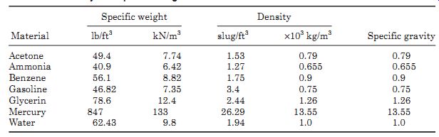
TABLE 1 Density and Specific Weights
3. Density and Specific Gravity
3.1 Basic terms
The density, specific weight, and specific gravity were defined in Chap. 5 as follows:
Density r of a material is defined as the mass per unit volume. Units of density are pounds (slug) per cubic foot [lb (slug)/ft^3] or kilogram per cubic meter (kg/m^3).
Specific weight g is defined as the weight per unit volume of a material, i.e., pounds per cubic foot (lb/ft^3) or newton per cubic meter (N/m^3).
Specific gravity (SG) of a liquid or solid is defined as the density of the material divided by the density of water or the specific weight of the material divided by the specific weight of water at a specified temperature. The specific gravity of a gas is its density/specific weight divided by the density/specific weight of air at 60°F and 1 atmosphere pressure (14.7 psia). The relation between density and specific weight is given by
g = r g (6)
where g is the acceleration of gravity 32.2 ft/s^2 or 9.8 m/s^2 depending on the units being used.
Table 1 gives a list of the density and specific weight of some common materials.
3.2 Density measuring devices
Hydrometers are the simplest device for measuring the specific weight or density of a liquid. The device consists of a graduated glass tube, with a weight at one end, which causes the device to float in an upright position. The device sinks in a liquid until an equilibrium point between its weight and buoyancy is reached. The specific weight or density can then be read directly from the graduations on the tube. Such a device is shown in Fig. 7a.
Thermohydrometer is a combination of hydrometer and thermometer, so that both the specific weight/density and temperature can be recorded and the specific weight/density corrected from lookup tables for temperature variations to improve the accuracy of the readings.
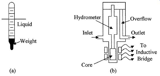
FIG. 7 (a) A basic hydrometer, (b) An induction hydrometer.
Induction hydrometers are used to convert the specific weight or density of a liquid into an electrical signal. In this case, a fixed volume of liquid set by the overflow tube is used in the type of setup shown in Fig. 7b, the displacement device, or hydrometer, has a soft iron or similar metal core attached. The core is positioned in a coil which forms part of a bridge circuit. As the density/specific weight of the liquid changes, the buoyant force on the displacement device changes. This movement can be measured by the coil and converted into a density reading.
Vibration sensors are an alternate method of measuring the density of a fluid (see Fig. 8a). Fluid is passed through a U tube which has a flexible mount so that it can vibrate when driven from an outside source. The amplitude of the vibration decreases as the specific weight or density of the fluid increases, so that by measuring the vibration amplitude the specific weight/density can be calculated.
Pressure at the base of a column of liquid of known height (h) can be measured to determine the density and specific gravity of a liquid. The density of the liquid is given by

(7)
The specific weight is given by (8)

The weight of a known volume of the liquid can be used to determine density, i.e., a container of known volume can be filled with a liquid and weighted full and empty. The difference in weight gives the weight of liquid, from which the density can be calculated using the following equation:

(9)
where Wf = weight of container + liquid
Wc = weight of container
Vol = volume of the container
Differential bubblers can be used to measure liquid density or specific weight.
FIG. 8b shows the setup using a bubbler system. Two air supplies are used to supply two tubes whose ends are at different depths in a liquid, the difference in air pressures between the two air supplies is directly related to the density of the liquid by the following equation:

(10)
where ?p is the difference in the pressures and ?h the difference in the height of the bottoms of the two tubes.
Radiation density sensors consist of a radiation source located on one side of a pipe or container and a sensing device on the other. The sensor is calibrated with the pipe or container empty, and then filled. Any difference in the measured radiation is caused by the density of the liquid which can then be calculated.
Gas densities are normally measured by sensing the frequency of vibration of a vane in the gas, or by weighing a volume of the gas and comparing it to the weight of the same volume of air.
3.3 Density application considerations
Ideally, when measuring the density of a liquid, there should be some agitation to ensure uniform density throughout the liquid. This is to avoid density gradients due to temperature gradients in the liquid and incomplete mixing of liquids at different temperatures. Excessive agitation should be avoided.
Density measuring equipment is available for extreme temperatures and pressures, i.e., from 150 to 600°F and for pressures in excess of 1000 psi. When measuring corrosive, abrasive, volatile liquids, and the like, radiation devices should be considered.
4. Viscosity
Viscosity was introduced in Sect. 7; it will be discussed in this Section in more detail.
4.1 Basic terms
Viscosity m in a fluid is the resistance to its change of shape, which is due to molecular attraction in the liquid that resists any change due to flow or motion.
When a force is applied to a fluid at rest, the molecular layers in the fluid tend to slide on top of each other as shown in Fig. 9a. The force F resisting motion in a fluid is given by

(11)
where A = boundary area being moved
V = velocity of the moving boundaries
y = distance between boundaries
m = coefficient of viscosity, or dynamic viscosity
The units of measurement must be consistent.
Sheer stress t is the force per unit area and is given in the following formula:

(12)
where t is the shear stress or force per unit area.
If F is in pounds, A in square feet, V in feet per second, and y in feet, then m is in pound seconds per square feet. Whereas, if F is in newton, A in square meter, V in meters per second, and y in meters, then m is in newton seconds per square meter. A sample list of fluid viscosities is given in Table 2.
The standard unit of viscosity is the poise, where a centipoise (poise/100) is the viscosity of water at 68.4°F. Conversions are given in here in Table 1. (1 centipoise = 2.09 × 10^-5 lb s/ft^2).
When the temperature of a body increases, more energy is imparted to the atoms making them more active and thus effectively reducing the molecular attraction. This in turn reduces the attraction between the fluid layers lowering the viscosity, i.e., viscosity decreases as temperature increases.
Newtonian fluids are fluids that exhibit only laminar flow as shown in Fig. 9a and are consistent with temperature. Only newtonian fluids will be considered.
Non-Newtonian fluid dynamics is complex and considered to be outside the scope of this text.
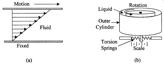
FIG. 9 Illustration of (a) Newtonian laminar flow and (b) a drag-type
viscometer.
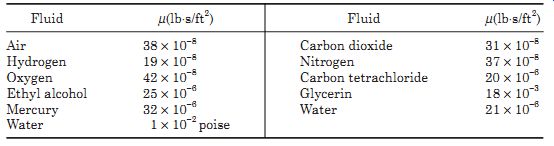
TABLE 2 Dynamic Viscosities, at 68°F and Standard Atmospheric Pressure
4.2 Viscosity measuring instruments
Viscometers or viscosimeters are used to measure the resistance to motion of liquids and gases. Several different types of instruments have been designed to measure viscosity, such as the inline falling-cylinder viscometer, the drag-type viscometer, and the Saybolt universal viscometer. The rate of rise of bubbles in a liquid can also be used to give a measure of the viscosity of a liquid.
The falling-cylinder viscometer uses the principle that an object when dropped into a liquid will descend to the bottom of the vessel at a fixed rate; the rate of descent is determined by the size, shape, density of the object, and the density and viscosity of the liquid. The higher the viscosity, the longer the object will take to reach the bottom of the vessel. The falling-cylinder device measures the rate of descent of a cylinder in a liquid and correlates the rate of descent to the viscosity of the liquid.
Rotating disc viscometer is a drag-type device. The device consists of two con centric cylinders and the space between the two cylinders is filled with the liquid being measured, as shown in Fig. 9b. The inner cylinder is driven by an electric motor and the force on the outer cylinder is measured by noting its movement against a torsion spring; the viscosity of the liquid can then be determined.
The Saybolt instrument measures the time for a given amount of fluid to flow through a standard size orifice or a capillary tube with an accurate bore. The time is measured in Saybolt seconds, which is directly related and can be easily converted to other viscosity units.
5. pH Measurements
5.1 Basic terms
In many process operations, pure and neutral water is required for cleaning or diluting other chemicals, i.e., the water is not acidic or alkaline. Water contains both hydrogen ions and hydroxyl ions. When these ions are in the correct ratio the water is neutral. An excess of hydrogen ions causes the water to be acidic and when there is an excess of hydroxyl ions, the water is alkaline. The pH (power of hydrogen) of the water is a measure of its acidity or alkalinity; neutral water has a pH value of 7 at 77°F (25°C). When water becomes acidic the pH value decreases. Conversely, when the water becomes alkaline the pH value increases. The pH values use a log to the base 10 scale, i.e., a change of 1 pH unit means that the concentration of hydrogen ions has increased (or decreased) by a factor of 10 and a change of 2 pH units means the concentration has changed by a factor of 100. The pH value is given by:
pH = log [1/hydrogen ion concentration] (13)
The pH value of a liquid can range from 0 to 14. The hydrogen ion concentration is in grams per liter, i.e., a pH of 4 means that the hydrogen ion concentration is 0.0001 g/l at 25°C. Strong hydrochloric or sulfuric acids will have a pH of 0 to 1.
4% caustic soda pH = 14
Lemon and orange juice pH = 2 to 3
Ammonia pH is about 11
5.2 pH measuring devices
The pH is normally measured by chemical indicators or by pH meters. The final color of chemical indicators depends on the hydrogen ion concentration; their accuracy is only 0.1 to 0.2 pH units. For indication of acid, alkali, or neutral water, litmus paper is used; it turns pink when acidic, blue when alkaline, and stays white if neutral.
A pH sensor normally consists of a sensing electrode and a reference electrode immersed in the test solution which forms an electrolytic cell, as shown in Fig. 10a. One electrode contains a saturated potassium chloride (alkaline) solution to act as a reference; the electrode is electrically connected to the test solution via the liquid junction. The other electrode contains a buffer which sets the electrode in contact with the liquid sample. The electrodes are connected to a differential amplifier, which amplifies the voltage difference between the electrodes, giving an output voltage that is proportional to the pH of the solution. FIG. 10b shows the pH sensing electrode.
5.3 pH application considerations
The pH of neutral water varies with temperature, i.e., neutral water has a pH of about 7.5 at 32°F and about 6 at 212°F. pH systems are normally automatically temperature compensated. pH test equipment must be kept clean and free from contamination. Calibration of test equipment is done with commercially available buffer solutions with known pH values. Again, cleaning between each reading is essential to prevent contamination.
Summary
This Section introduced humidity, its relation to dew point, and temperature.
The psychrometric chart is shown and instructions given on how to read the chart. Humidity terms and instruments are described. Density, specific weight, and specific gravity are defined together with measurement instruments. Viscosity and pH were introduced with definitions and measuring instruments.
The prime points discussed in this Section were as follows:
1. The definition of and relationship between specific humidity, relative humidity, and dew point
2. Use of the psychrometric chart for obtaining dew point and the weight of water vapor dissolved in the atmosphere from temperature data
3. The various types of instruments used for the direct and indirect measurement of humidity
4. Density, specific weight, and specific gravity are defined with examples in both English and SI units. Instruments for measuring specific weight and specific gravity are given
5. Instruments used in the measure of density and specific weight
6. The basic terms and definitions used in viscosity, its relation to flow with examples, and instruments used for measuring viscosity
7. An introduction to pH terms, its value when determining acidity or alkalinity, and the instruments used to measure pH.
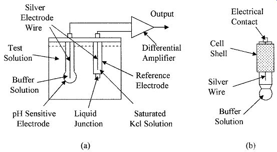
FIG. 10 Shows the set up of (a) a pH sensor and (b) a pH sensing electrode.
Problems
1 The dry bulb of a wet/dry thermometer reads 120°F. What is the relative humidity if the wet bulb reads (a) 90°F, (b) 82°F, (c) 75°F?
2 The wet bulb of a wet/dry thermometer reads 85°F. What will the dry bulb read if the relative humidity is (a) 80 percent, (b) 60 percent, (c) 30 percent?
3 What is the relative humidity if the wet and dry bulbs in a wet/dry thermometer read 75°F and 85°F respectively?
4 The dry bulb of a wet/dry thermometer reads 60°F, and the relative humidity is 47 percent. What will the wet bulb read and what is the absolute humidity?
5 The wet and dry bulbs of a wet/dry thermometer read 75°F and 112°F, respectively. What is the relative and absolute humidity?
6 If the air temperature is 85°F, what is the water vapor pressure corresponding to a relative humidity of 55 percent and at 55°F with 85 percent relative humidity?
7 How much water is required to raise the relative humidity of air from 25 to 95 percent if the temperature is held constant at 95°F?
8 How much heat and water are added per pound of dry air to increase the relative humidity from 15 to 80 percent with a corresponding temperature increase from 42 to 95°F?
9 How much water does dry air contain at 105°F and 55 percent relative humidity?
10 How much heat is required to heat one pound of dry air from 35 to 80°F if the relative humidity is constant at 80 percent ?
11 How much space is occupied by 4.7 lb of dry air if the air temperature is 80°F and the relative humidity is 82 percent?
12 The two tubes in a bubbler system are placed in a liquid with a density of 1.395 slugs/ft^3. If the bottom ends of the bubbler tubes are 3.5 and 42.7 in below the surface of the liquid, what is the differential pressure supplied to the two bubblers?
13 A tank is filled to a depth of 54 ft with liquid having a density of 1.234 slugs/ft^3. What is the pressure on the bottom of the tank?
14 What would be the SG of a gas with a specific weight of 0.127 lb/ft^3 , if the density of air under the same conditions is 0.0037 slugs/ft^3?
15 A square plate 1.2 ft on a side is centrally placed in a channel 0.23-in wide filled with a liquid with a viscosity of 7.3 × 10⁻⁵ lb s/ft^2. If the plate is 0.01-in thick what force is required to pull the plate along the channel at 14.7 ft/s?
16 Two parallel plates 35 ft 2 , 1.7-in apart are placed in a liquid with a viscosity of 2.1 × 10^-4 lb s/ft^2. If a force of 0.23 lb is applied to one plate in a direction parallel to the plates with the other plate fixed, what is the velocity of the plate?
17 What is the pH of a solution, if there is a concentration of 0.0006 g/L of hydrogen ions?
18 What is the change in hydrogen concentration factor if the pH of a solution changes from 3.5 to 0.56?
19 What is the concentration of hydrogen ions if the pH is 13.2?
20 What is the hydrogen concentration of a neutral solution?
Related Articles -- Top of Page -- Home