AMAZON multi-meters discounts AMAZON oscilloscope discounts
Objectives
This Section is an introduction to actuators and actuator control and will help you understand the operation of control devices and their use in flow control.
Topics covered in this Section are as follows:
_ The operation and use of various types of self-regulating devices and loading used in gas regulators
_ Closed loop pneumatic, hydraulic, and electrical liquid flow valves
_ Fail-safe operation in valves
_ The various types of valves in use
_ Valve characteristics
_ Electronic power control devices
_ Methods of applying feedback for position control
_ Relays and motors for actuator control
This section deals with control devices used for regulating temperature, pres sure, controlling liquid, and gas flow in industrial processing. The devices can be self-regulating or under the control of a central processing system that can be monitoring and controlling many variables.
1. Introduction
This section will discuss actuators and regulators and their use for the control of gas flow, liquid flow, and pressure control. In many processes this involves the control of many thousands of cubic meters of a liquid or the control of large forces, as would be the case in a steel rolling mill from low-level analog, digital, or pneumatic signals. Temperature can also normally be controlled by regulating gas and/or liquid flow. Control loops can be local self-regulating loops under pneumatic, hydraulic, or electrical control, or the loops can be processor controlled with additional position feedback loops. Electrical signals from a controller are low-level signals that require the use of relays for power control or amplification and power switching devices, and possibly opto-isolators for isolation. These power control devices are normally at the point of use so that electrically controlled actuators and motors can be supplied directly from the power lines.
2. Pressure Controllers
2.1 Regulators
Gases used in industrial processing, such as oxygen, nitrogen, hydrogen, and propane, are stored in high-pressure containers in liquid form. The high-pressure gases from above the liquid are reduced in pressure and regulated with gas regulators to a lower pounds per square inch before they can be distributed through the facility. The gas lines may have additional regulators at the point of use.
A spring-controlled regulator is an internally controlled pressure regulator and is shown in Fig. 1a. Initially, the spring holds the inlet valve open and gas under pressure flows into the main cylinder at a rate higher than it can exit the cylinder. As the pressure in the cylinder increases, a predetermined pressure is reached where the spring loaded diaphragm starts to move up, causing the valve to partially close, i.e., the pressure on the diaphragm controls the flow of gas into the cylinder to maintain a constant pressure in the main cylinder and at the output, regardless of the flow rate (ideally). The output pressure can be adjusted by the spring screw adjustment.
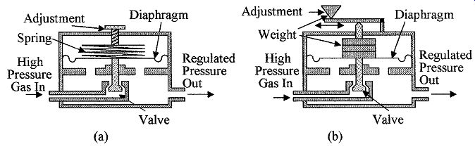
FIG. 1 Self-compensating pressure regulators (a) spring loaded and
(b) weight loaded.
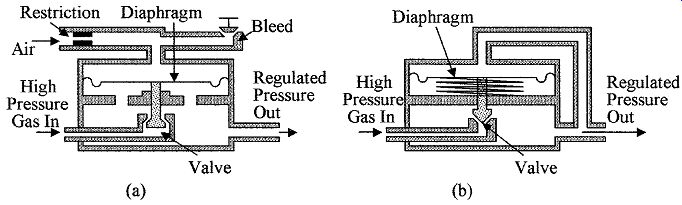
FIG. 2 Self-compensating pressure regulators (a) internal pressure-loaded
regulator and (b) externally connected spring-loaded regulator.
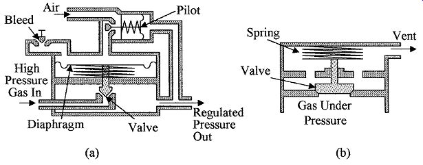
FIG. 3 Shown are (a) a pilot-operated regulator and (b) an automatic
pressure safety valve.
A weight-controlled regulator is shown in Fig. 1b. The internally controlled regulator has a weight-loaded diaphragm. The operation is the same as the spring-loaded diaphragm except the spring is replaced with a weight. The pres sure can be adjusted by the position of a sliding weight on a cantilever arm.
A pressure-controlled diaphragm regulator is shown in Fig. 2a. The internally controlled regulator has a pressure-loaded diaphragm. Pressure from a regulated external air or gas supply is used to load the diaphragm via a restriction. The pressure to the regulator can then be adjusted by an adjustable bleed valve, which in turn is used to set the output pressure of the regulator.
Externally connected spring diaphragm regulator is shown in Fig. 2b. The cross section shows an externally connected spring-loaded pressure regulator.
The spring holds the valve open until the output pressure, which is fed to the upper surface of the diaphragm, overcomes the force of the spring on the diaphragm, and starts to close the valve, hence regulating the output pressure.
Note that the valve is inverted from the internal regulator and the internal pres sure is isolated from the lower side of the diaphragm. Weight- and air-loaded diaphragms are also available for externally connected regulators.
Pilot-operated pressure regulators can use an internal or external pilot for feed back signal amplification and control. The pilot is a small regulator positioned between the pressure connection to the regulator and the loading pressure on the diaphragm. FIG. 3a shows such an externally connected pilot regulator.
The pressure from the output of the regulator is used to control the pilot, which in turn amplifies the signal and controls the pressure from the air supply to the diaphragm, giving greater control than that available with the internal pres sure control diaphragm. A slight change in the output pressure is required to produce a full pressure range change of the regulator giving a high gain system for good output pressure regulation.
An Instrument pilot-operated pressure regulator is similar to the pilot-operated pressure regulator but has a proportional band adjustment included, giving a gain or sensitivity control feature to provide greater flexibility in control.
2.2 Safety valves
Safety valves are fitted to all high-pressure containers from steam generators to domestic water heaters (see Fig. 3b). The valve is closed until the pressure on the lower face of the valve reaches a predetermined level set by the spring.
When this level is reached, the valve moves up allowing the excess pressure to escape through the vent.
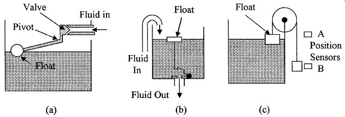
FIG. 4 Various types of regulators are shown (a) automatic fluid level
controller, (b) automatic emptying of a storage tank when full, and (c)
means of detecting full level or empty level in a fluid reservoir.
2.3 Level regulators
Level regulators are in common use in industry to maintain a constant fluid pres sure, or a constant fluid supply to a process, or in waste storage. Level regulators can be a simple float and valve arrangement as shown in Fig. 4a to using capacitive sensors as given in Chap. 6 to control a remote pump. The arrangement shown in Fig. 4a is used to control water levels in many applications. When the fluid level drops due to use, the float moves downward opening the inlet valve and allowing fluid to flow into the tank. As the tank fills, the float rises, causing the inlet valve to close, thus maintaining a constant level and preventing the tank from overflowing.
FIG. 4b shows an example of a self-emptying reservoir when a predetermined fluid level is reached, as may be used in a waste holding tank. As the tank fills, the float rises to where the connecting link from the float to the valve becomes taut and overcomes the hydrostatic pressure on and lifting the outlet valve. Once lifted, the fluid pressure under the valve balances the pressure above the valve and the buoyancy of the valve will keep it open until the tank is empty, then it will close. Once closed the reservoir will start to fill and the fluid pressure on the top surface of the valve will hold it closed. The automatic fluid leveler in Fig. 4a can be combined with the emptying system in Fig. 4b.
In this case, the outlet valve is manually or automatically operated to deliver a known volume of liquid to a process, as required. The container automatically refills for the next operation cycle.
The position of the weight in Fig. 4c is controlled by the float. The position of the weight is monitored by position sensors A and B. When the weight is in position A (container empty), the sensor can be used to turn on a pump to fill the tank and when sensor B senses the weight (container full) it can be used to turn the pump off. The weight can be made of a magnetic material and the level sensors would be Hall effect or magneto resistive element (MRE) devices.
3. Flow Control Actuators
When a change in a measured variable with respect to a reference has been sensed, it is necessary to apply a control signal to an actuator to make corrections to an input controlled variable to bring the measured variable back to its preset value. In most cases any change in the variables, i.e., temperature, pres sure, mixing ingredients, and level, can be corrected by controlling flow rates.
Hence, actuators are in general used for flow rate control and can be electrically, pneumatically, or hydraulically controlled. Actuators can be self-operating in local feedback loops in such applications as temperature sensing with direct hydraulic or pneumatic valve control, pressure regulators, and float level controllers. There are two common types of variable aperture actuators used for flow control; they are the globe valve and the butterfly valve.
3.1 Globe valve

FIG. 5 Cross section of (a) a globe valve with a linear flow control
plug and (b) different flow patterns for various plugs versus plug travel.
The globe valve's cross section is shown in Fig. 5a. The actuator can be driven electrically using a solenoid or motor, pneumatically or hydraulically. The actuator determines the speed of travel and distance the valve shaft travels. The globe type valve can be designed for quick opening, linear, or equal percentage operation.
In equal percentage operation the flow is proportional to the percentage the valve is open, or there is a log relationship between the flow and valve travel. The shape of the plug determines the flow characteristics of the actuator and is normally described in terms of percentage of flow versus percentage of lift or travel.
The valve plug shown in Fig. 5a gives a linear relationship between flow and lift. The characteristic is given in Fig. 5b. Also shown in the graph are the characteristics for a quick opening plug and an equal percentage plug to illustrate some of the characteristics that can be obtained from the large number of plugs that are available. The selection of the type of control plug should be carefully chosen for any particular application. The type will depend on a careful analysis of the process characteristics, i.e., if the load changes are linear a linear plug should be used. Conversely, if the load changes are nonlinear a plug with the appropriate nonlinear characteristic should be used.
The globe valve can be straight through with single seating as illustrated in Fig. 5a or can be configured with double seating, which is used to reduce the actuator operating force, but is expensive, difficult to adjust and maintain, and does not have a tight seal when shutoff. Angle valves are also available, i.e., the output port is at right angles or 45° to the input port.
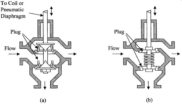
FIG. 6 Cross sections of globe valve configurations: (a) two-way valve
and (b) three-position valve.
Many other configurations of the globe valve are available. Illustrated in Fig. 6a is a two-way valve (diverging type), which is used to switch the incoming flow from one exit to another. When the valve stem is up the lower port is closed and the incoming liquid exits to the right, and when the valve is down the upper port is closed and the liquid exits from the bottom. Also available is a converging-type valve, which is used to switch either of the two incoming flows to a single output. FIG. 6b illustrates a three-way valve.
In the neutral position both exit ports are held closed by the spring. When the valve stem moves down the top port is opened and when the valve stem moves up from the neutral position the lower port is opened.
Other types of globe valves are the needle valve (less than 1-in diameter), the balanced cage-guided valve, and the split body valve. In the cage-guided valve, the plug is grooved to balance the pressure in the valve body. The valve has good sealing when shut off. The split body valve is designed for ease of maintenance and can be more cost effective than the standard globe valve, but pipe stresses can be transmitted to the valve and cause it to leak. Globe valves are not well suited for use with slurries.
3.2 Butterfly valve
The butterfly valve is shown in Fig. 7a and its flow versus travel characteristics are shown in Fig. 7b. The relation between flow and lift is approximately equal percentage up to about 50 percent open, after which it is linear. Butterfly valves offer high capacity at low cost, are simple in design, easy to install, and have tight closure. The torsion force on the shaft increases until open up to 70° and then reverses.
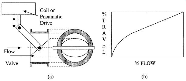
FIG. 7 Cross section of (a) a butterfly valve and (b) its flow versus
travel characteristic.
3.3 Other valve types
A number of other types of valves are in common use. They are the weir diaphragm, ball, and rotary plug valves. The cross sections of these valves are shown in Fig. 8.
A weir-type diaphragm valve is shown in Fig. 8a. The valve is shown open;
closure is achieved by forcing a flexible membrane down onto the weir.
Diaphragm valves are good for slurries and liquids with suspended solids, are low cost devices, but tend to require high maintenance, and have poor flow characteristics.
A one-piece ball valve is shown in Fig. 8b. The valve is a partial sphere that rotates. The valve tends to be slow to open. Other than the one shown in the figure, the ball valve is available in other configurations also with spheres of various shapes for different flow characteristics. The valve is good for slurries and liquids with solid matter because of its self-cleaning operation. Ball valves have tight turnoff characteristics, are simple in design, and have greater capacity than similar-sized globe valves.
An eccentric rotary plug valve is shown in Fig. 8c. The valve is of medium cost but requires less closing force than many valves and can be used for forward or reverse flow. The valve has tight shutoff with positive seating action, has high capacity, and can be used with corrosive liquids.
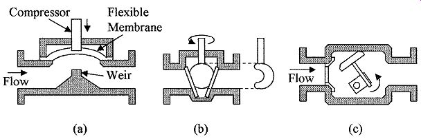
FIG. 8 Different valve types (a) diaphragm, (b) one-piece ball valve,
and (c) rotary plug valve.
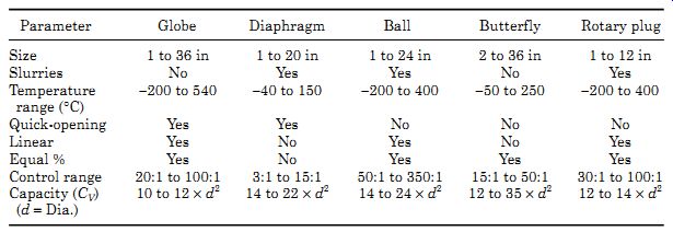
TABLE 1 Valve Characteristics
3.4 Valve characteristics
Other factors that determine the choice of valve type are corrosion resistance, operating temperature ranges, high and low pressures, velocities, and fluids containing solids. Correct valve installation is essential; vendor recommendations must be carefully followed. In situations where sludge or solid particulates can be trapped upstream of a valve, a means of purging the pipe must be available. To minimize disturbances and obtain good flow characteristics a clear run of 1 to 5 pipe diameters up and down stream should be allowed.
Valve sizing is based on pressure loss. Valves are given a CV number that is based on test results. The CV number is the number of gallons of water flowing per minute through a fully open valve at 60°F (15.5°C) that will cause a pres sure drop of 1 psi (6.9 kPa). It implies that when flowing through the fully opened valve, it will have a pressure drop of 1 psi (6.9 kPa), i.e., a valve with a CV of 25 will have a pressure drop of 1 psi when 25 gal of water per minute is flowing through it. For liquids, the relation between pressure drop Pd (pounds per square inch), flow rate Q (gallon per minute), and CV is given by
CV = Q ×v(SG/Pd) ( 1)
where SG is the specific gravity of the liquid.
Table 1 gives a comparison of some of the valve characteristics; the values shown are typical of the devices available and may be exceeded by some manufacturers with new designs and materials.
3.5 Valve fail safe
An important consideration in many systems is the position of the actuators when there is a loss of power, i.e., will chemicals or the fuel to the heaters continue to flow or will a total system shut down occur? FIG. 9 shows an example of a pneumatically or hydraulically operated globe valve design that can be configured to go to the open or closed position during a system failure.
The modes of failure are determined by simply changing the spring position and the pressure port.
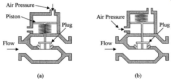
FIG. 9 Fail-safe pneumatic or hydraulic operated valves: with the
loss of operating pressure on the valve, the valve in (a) will open and
the valve in (b) will close.
In Fig. 9a the globe valve is closed by applying pressure to the pressure port to oppose the spring action. If the system fails, i.e., if there is a loss of pneumatic pressure, the spring acting on the piston will force the valve to revert back to its open position. In Fig. 9b the spring is removed from below the piston to a position above the piston and the inlet and exhaust ports are reversed. In this case the valve is opened by the applied pressure working against the spring action. If the system fails and there is a loss of control pressure, the spring action will force the piston down and close the valve. Similar fail-safe electrically and hydraulically operated valves are available. Two-way and three-way fail-safe valves are also available which can be configured to be in a specific position when the operating system fails.
4. Power Control
Electrical power for actuator operation can be controlled from low-level analog and digital signals using electronic power devices or magnetic contactors.
Magnetic contactors have a lower ON resistance than electronic devices but require higher drive power. Contactors provide voltage isolation between the control signals and output power circuits, but are slow to switch, have lower cur rent handling capability than electronic power devices, and have a limited switching life. In electronic devices the problem of electrical isolation between drive circuits and output power circuits can easily be overcome with the use of opto-isolators. Electronic power devices have excellent longevity and are very advantageous due to their switching speeds in variable power control circuits.
4.1 Electronic devices
A number of electronic devices such as the silicon-controlled rectifier (SCR), TRIAC, and metal-oxide semiconductor (MOS) devices can be used to control several hundred kilowatts of power from low-level electrical signals. Electronic power control devices fall into two categories. First, triggered devices such as SCR and TRIAC that are triggered by a pulse on the gate into the conduction state, once triggered can only be turned off by reducing the anode/cathode cur rent to below their sustaining current, i.e., when the supply voltage/current drops to zero. But these devices can block high reverse voltages. Hence, they can be extensively used in ac circuits where the supply regularly transcends through zero turning the device OFF automatically. The second group of devices are Darlington bipolar junction transistors (BJT), power metal-oxide semiconductor field effect transistor (MOSFET), insulated gate bipolar transistors (IGBT), and MOS-controlled thyristors (MCT). These devices are turned ON and OFF by an input control signal, but do not have the capability of high reverse volt age blocking. Hence, this group of devices are more commonly used with dc power supplies or biased to prevent a reverse voltage across the device.
The SCR is a current-operated device and can only be triggered to conduct in one direction, i.e., when used with an ac supply it blocks the negative half-cycle and will only conduct on the positive half cycle, when triggered. Once triggered, the SCR remains ON for the remaining portion of the half-cycle. FIG. 10a shows the circuit of an SCR with a load. Figures 11.10b and c show the effects of triggering on the load voltage (VL). By varying the triggering in relation to the positive half cycle, the power in the load can be controlled from 0 to 50 percent of the total available power. Power can be controlled from 50 to 100 percent by putting a diode in parallel with the SCR to conduct current on the negative half cycle. Light activated SCRs are also available.
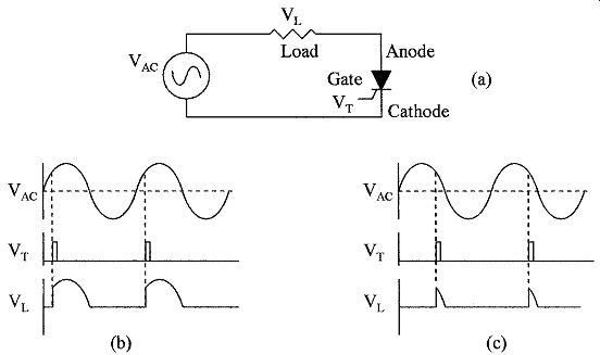
FIG. 10 (a) SCR circuit with load, (b) Waveforms with early triggering,
and (c) Waveforms with late (low power to load) triggering.
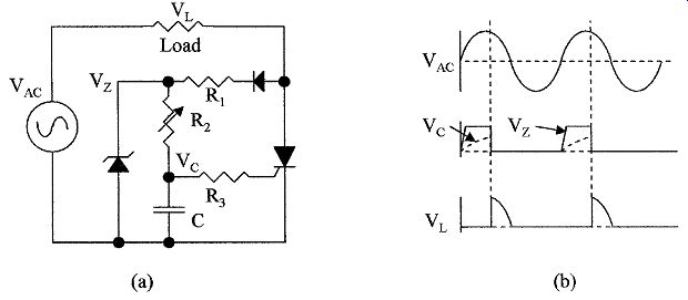
FIG. 11 (a) Atypical SCR triggering circuit with trigger point control
and (b) triggering waveforms.
One method of triggering the SCR is shown in Fig. 11a with the corresponding circuit waveforms shown in Fig. 11b. During the positive half-cycle the capacitor C is charged via R1 and R2 until the triggering point of the SCR is reached. The diode can be connected on either side of the load. The advantage of connecting the diode to the SCR side of the load is to turn OFF the volt age to the gate when the SCR is fired, thus, reducing dissipation. The diode is used to block the negative half-cycle from putting a high negative voltage on the gate and damaging the SCR. The zener diode is used to clamp the positive going half-cycle at a fixed voltage (VZ) so that the capacitor (VC) has a fixed aiming voltage, giving a linear relation between triggering time and potentiometer set ting. This is shown by VZ and VC in Fig. 11b.
A control of 0 to 100 percent can be obtained with a single SCR in a bridge circuit as shown in Fig. 12a; the waveforms are shown in Fig. 12b. The bridge circuit changes the negative going half-cycles into positive half-cycles so that the SCR only sees positive half-cycles and is triggered during every half cycle, and is turned OFF every half-cycle when the supply voltage goes to zero.
As shown in the Fig. 12a the system is controlled by a low level signal coupled to the SCR trigger circuit via an opto-isolator. The triggering point is set by potentiometer R and capacitor C; as the SCR only sees positive voltages, the diode in not required. For cheapness the zener diode is omitted. As in the previous figure, resistor R can be connected to either side of the load.
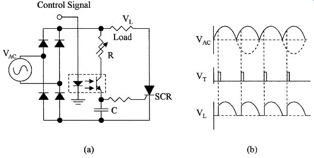
FIG. 12 Bridge circuit for SCR control (a) using full-wave rectification
and (b) waveforms.
The DIAC is a semiconductor device developed for trigger control primarily for use with TRIACs. FIG. 13a shows the symbol for the device and (b) the device's characteristic. The DIAC is a two-terminal symmetrical switching device. As the voltage increases across the device, little current flows until the breakdown voltage VL is reached. At this point the device breaks down and con ducts as shown. The breakdown occurs with both positive and negative voltages.
The breakdown voltage of the DIAC is used to set the trigger voltage for the TRIAC; when the device breaks down the TRIAC triggers.
TRIACs can be considered as two reversed SCRs connected in parallel. They can be triggered on both the positive and negative half-cycles of the ac wave form. A circuit for triggering a TRIAC is shown in Fig. 14a with the associated waveforms shown in Fig. 14b. The TRIAC can be used to control power to the load from 0 to 100 percent by controlling the trigger points with respect to the ac sine wave. As the ac voltage increases from zero, VZ is clamped by the zener diodes in both the positive and negative directions. The capacitor C is then charged via R2 until the breakdown voltage of the DIAC is reached and the TRIAC is triggered on both the positive and negative half-cycles as shown by the waveforms in Fig. 14b.
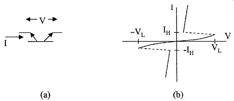
FIG. 13 DIAC used in SCR and TRIAC triggering circuits (a) symbol
and (b) characteristic.
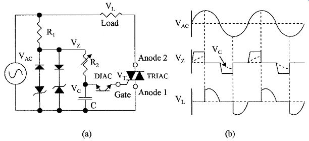
FIG. 14 A TRIAC can control power from 0 to 100 percent (a) shows
the TRIAC power control circuit and (b) the circuit waveforms.
This example illustrates that the efficiency of the switch >98 percent, and also the high dissipation that can occur in the switch and the need for cooling fins with low thermal resistance. Precautions in the design of power switching circuits, choices of devices for specific applications, and thermal limitations are out side the scope of this guide. Device data sheets must be consulted and advice obtained from device manufacturers before designing power controllers.
Power devices that have an input control are as follows:
1. Darlington Bipolar Junction Transistors (BJT) are current-controlled devices. Power bipolar devices have low gain and so are normally used in a Darlington configuration to give high current gain and the ability to control high currents with low drive currents.
2. Power MOSFETs are voltage-controlled devices designed for high-speed operation, but their high saturation voltage and temperature sensitivity limits their application in power circuits.
3. Insulated Gate Bipolar Transistor (IGBT), as opposed to the Darlington bipolar configuration, is controlled by a MOS transistor making it a voltage-controlled device. The IGBT has fast switching times. Older devices had a high saturation voltage; newer devices have a saturation voltage about the same as a BJT.
4. MOS-Controlled Thyristor (MCT) is a voltage-controlled device with a low saturation voltage and medium speed switching characteristics.
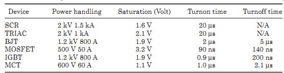
TABLE 2 Comparison of Power Device Characteristics
A comparison of the power devices characteristics is given in Table 2. These devices are used for power and motor control. Applications include rectification of multiphase ac power to give a variable voltage dc power level output or the control of dc motors from an ac power source, the control of multiphase motors from a dc power source, or the conversion of dc power to multiphase ac power.
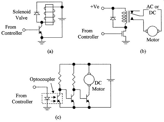
FIG. 15 Options are shown for driving a motor or actuator from a controller
output (a) via a power transistor, (b) via a relay, and (c) using an opto-coupler.
4.2 Magnetic control devices
A signal from a controller is a low-level signal but can be amplified to control an actuator or small motor. Power for actuators are normally generated close to the point of use to prevent energy loss in the leads and to prevent large currents from flowing in the ground return lines to the controller to minimize offset and ground line noise. In Fig. 15a a power transistor is used to drive a solenoid valve. A diode
is used across the solenoid to protect the transistor from the high voltage inductive overshoot that occurs on switch-off. In Fig. 15b a MOS device is used to drive a motor control relay. Because of the isolation the relay gives between the driving circuit and the motor circuit, the motor and power supply can be either dc or ac. Such a circuit can be extended to driving multi-contact relays to control three-phase ac motors and multiple signal paths. Relays for switching high cur rents and voltages that are used for motor control are called contactors.
FIG. 15c shows the use of an opto-coupler to isolate the controller from the motor circuit. While both circuits are electrically isolated, the circuit as shown can only be used to drive a dc motor. However, because of the isolation given by the opto-coupler, the circuit can be expanded to drive three-phase ac motors. The opto-coupler consists of a light emitting diode (LED) optically coupled to a phototransistor; a current (10 to 30 mA) activates the diode; light from the diode turns ON the phototransistor. When there is no current flowing in the LED, no light is emitted and the phototransistor is OFF. As previously mentioned, solid state relays are available that have the power device (TRIAC) included in the package with the opto-coupler for direct motor control.
Contactors are designed for switching high currents and voltages, such as are used in motor control applications. A single-pole single-throw double-break contactor is shown in Fig. 16. In Fig. 16a the contactor is shown de-energized and the contacts are open. When a current is passed through the coil, the magnetic field in the core attracts and pulls in the soft iron keeper which closes the contacts as shown in Fig. 16b. Contactors can have multiple contacts for multiphase motors. Contact material is critical, as chemical and metallurgical actions occur during switching causing wear, high contact resistance, and welding. Gold or rhodium can be used for currents below 1 A. Silver is used for cur rents in the 1 to 10 A range for supply voltages above 6 V. Silver cadmium is sometimes used for currents in the range 5 to 25 A when the supply voltage is above 12 V. Mercury wetted contacts are available for currents up to 100 A. The contact life in relays is limited to typically between 100 and 500 K operations.
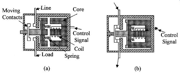
FIG. 16 A contactor is used for high current and voltage switching,
the contactor shown is (a) de-energized and (b) energized.
5. Motors
The student needs to be aware of the types of functions the motors perform in industrial applications, but details of motors and control circuits are outside the scope of this text. Motors are used for pumping fluids, compressors, driving conveyer belts, and any form of positioning required in industry. For control applications or positioning, servos or stepper motors are used.
5.1 Servo motors
Servo motors can rotate to a given position, be stopped, and reversed. In the case of a servo motor the angular position and speed can be precisely controlled by a servo loop, which uses feedback from the output to the input. FIG. 17a shows such a system. The position of the output shaft is monitored by a potentiometer which provides an analog feedback voltage to the control electronics (an encoding disc would be used in a digital system), so that the control electronics can use this information to power the output motor and stop it in any desired position or reverse the motor to stop at any desired position.
5.2 Stepper motors
Stepper motors rotate at a fixed angle with each input pulse. The rotor is normally a fixed magnet with several poles and a stator with several windings. Eight magnetic poles and a six-section stator are shown in Fig. 17b. Stepper motors are available in many different designs with a wide selection of the number of poles and drive requirements, all of which define the stepper motor characteristics and rotation angle for each input phase. Stepper motors can be reversed by changing the sequence of the driving phases. Stepper motors are available with stepping angles of 0.9, 1.8, 3.6, 7.5, 15, and 18 degrees. Since the motor steps a known angle with each input pulse, feedback is not required. However, as only the relative position is known, loss of power will cause loss of position information, so that in a system using stepper motors a position reference is usually required.
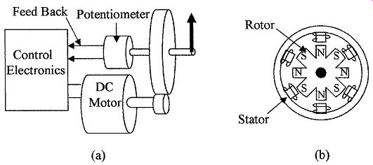
FIG. 17 Illustrated is (a) a servomotor with a feedback loop and (b)
a stepper motor.
5.3 Valve position feedback
In Fig. 18a a globe valve operated by an electric motor is shown. The screw driven by the motor can move the plug in the valve up or down. A potentiometer wiper is attached to the valve stem and gives a resistance directly proportional to the amount the valve is open. This resistance value can be fed back to the controlling electronics, so that the position of the valve can be monitored.
The system could also be digital, in which case, a digital encoding technique would be used for feedback.
5.4 Pneumatic feedback
In Fig. 18b pneumatic control is used in a local closed loop system for maintaining water at a set temperature. Cold water and steam are mixed in a heat exchanger; the temperature of the exiting hot water is monitored by a pressure- spring thermometer. The pressure from the thermometer is used to operate and control a linear globe valve in the incoming steam pipe. If the temperature of the hot water increases above a set temperature, the pressure from the thermometer increases and starts to close the valve in the steam line, keeping the hot water at the set temperature. If the flow of hot water increases, the temperature of the water will start to lower and this will reduce the pressure from the thermometer to the valve increasing the steam flow, bringing the tempera ture back to its set point.
6. Application Considerations
6.1 Valves
The selection of control valves for a particular application depends on many variables; such as the corrosive nature of the fluid, temperature of operation, pressures involved, high or low flow velocities, volume of flow, and the amount of suspended solids.
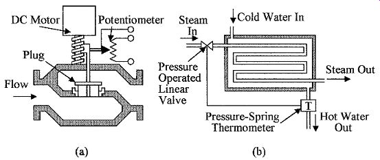
FIG. 18 (a) A dc electric motor operated valve with position feedback
potentiometer and (b) a self-regulating pneumatic temperature controller.
Valves are the final element in a control loop and are critical in providing the correct flow for process control. The valve is subject to operation in very harsh conditions and one of the most costly elements in the process control system. The choice and correct installation requires both knowledge and experience. Careful attention must be paid to the system requirements and manufacturers' specifications, only then can a careful valve selection be made (additional information can be obtained from the ISA 75 series of standards).
Some of the factors affecting the choice of valves are as follows:
1. Type of valve for two-way or three-way fail-safe considerations, and so on.
2. Valve size from flow requirements; care must be taken to avoid both oversizing and undersizing.
3. Materials used in the valve construction, considering pressure, size, and corrosion. Materials used in valves range from PVC to brass to steel.
4. Tightness of shutoff: Valves are classified by quality of shutoff by leakage at maximum pressure. Valves are classified into six classes depending on leak age from 0.5 percent of rated capacity to 0.15 mL/min. for a 1-in dia. valve.
5. Acceptable pressure drop across the valve.
6. Valve body for linear or rotary motion, i.e., globe, diaphragm versus ball, butterfly, and so forth.
The type of valve or plug depends on the nature of the process reaction. In the case of a fast reaction with small load changes, control is only slightly affected by valve characteristics. When the process is slow with large load changes, valve characteristics are important, i.e., if the load change is linear, a valve with a linear characteristic should be used, in the case of a nonlinear load change, a valve with an equal percentage change may be required. In some applications valves are required to be completely closed when OFF. Other considerations are maintenance, serviceability, fail-safe features, pneumatic, hydraulic, solenoid or motor control, and the need for feedback. The above is a limited review of actuator valves, as previously noted, the manufacturer's data sheets should be consulted when choosing a valve for a particular application.
Position and speed are normally controlled by electric operated servo or stepper motors. In pumping, compressors, conveyer belt, and like applications, three-phase motors are normally used.
6.2 Power devices
Power switching devices from contactors to solid state devices will be chosen from considerations of power handling, switching speed, isolation, and cost. Some of the considerations are as follows:
1. For low-speed operation, mechanical relay devices can be used, which will give isolation, relatively low dissipation, and are low cost.
2. Light control and ac motor control can use SCRs and TRIACs. These devices are packaged in a wide range of packages depending on current handling and heat dissipation requirements.
3. For power control, multiphase motor control, and high-speed switching applications BJTs or IGBTs can be used. These devices also come in a variety of low thermal resistance packages.
4. The MOSFET device can be used in medium power applications. The device has the advantage that control circuits can be integrated on to the same die as the power device.
Summary
This Section discussed the type of valves used to control the manipulated vari able, the types of actuators used, and control of power to the actuators.
The main points discussed were as follows:
1. The type of self-regulating gas pressure regulators used in process control, the internal and external loading of the regulators using springs, weights, pressure, and pressure amplifiers.
2. Various methods of automatically controlling liquid levels.
3. A wide variety of control valves are available for flow control. A comparison of their characteristics is given and some options available when choosing a control valve for a specific application are also discussed.
4. Flow control actuators are designed with different control characteristics for different applications such as linear, quick opening valves, and equal percentage valves. The proper characteristics should be chosen for the application.
5. Fail-safe valve configurations are needed to prevent the flow of material during a system failure or loss of power. Valve configurations are shown for valves to fail in the open position or in the closed position.
6. Electronic power control devices are now available for efficient power control with high-speed switching characteristics. The characteristics of the different devices are compared and the control circuits are shown.
7. Magnetic relays and contactors are used for electrical isolation between signal voltage levels and high voltage levels. The devices are used for motor and actuator control.
8. Servo motors and stepper motors are used for position control. It is necessary to feedback to the control system the position of actuator and the like being controlled. Potentiometers for electrical position feedback are shown.
Problems
1 What is the prime use of a regulator?
2 Where is an actuator used?
3 What is an instrument pilot operated pressure regulator?
4 What do you understand by fail-safe "open"?
5 What are the methods used to load regulators?
6 What are the methods used to control actuators?
7 Where are electrical contactors used?
8 How is the position of a valve communicated back to the controller?
9 When are opto-isolators used?
10 Where would you use a safety valve?
11 Why is a DIAC used in a TRIAC trigger circuit?
12 Name the various types of electronic power control devices?
13 What are the differences between the SCR and the TRIAC?
14 What are the differences between the TRIAC and the IGBT?
15 Name the various types of valve families.
16 Name the various valve configurations that can be found within the globe valve family.
17 A valve has a CV of 88. What is the pressure drop in the valve when 1.8 gal/s of a liquid with a SW of 78 lb/ft^3 is flowing?
18 Describe a three-position globe valve.
19 In Fig. 14, a TRIAC with a 5 V trigger level is used with 12 V zeners. It is required to be able to control the power in the load from full to half power. What is the value of the capacitor C if the potentiometer R2 is 25 kOhm?
20 In Fig. 12 the load is 0.5 Ohm. If the supply is 120 V ac, what is the maximum power that can be supplied to the load and the power loss in the SCR and diodes? Assume the voltage drop across the SCR and a diode is 1.6 V and 1.5 V, respectively.
Related Articles -- Top of Page -- Home