AMAZON multi-meters discounts AMAZON oscilloscope discounts
Objectives
This Section will help you understand why signal conditioning is required in process control and to familiarize you with signal conditioning methods.
The following are covered in this Section:
_ The conversion of sensor signals into pneumatic or electrical signals
_ Signal linearization, methods of setting signal zero level, and span
_ Nonlinear analog amplifiers
_ Digital linearization
_ The difference between sensors, transducers, and converters
_ Conditioning for local displays and transmission
_ Temperature compensation used in signal conditioning
_ Signal conditioning used with Hall effect and magneto resistive element (MRE) devices
_ Considerations using capacitive devices
_ Resistance temperature detectors (RTD) signal conditioning
Many sensors do not have a linear relationship between the physical variable and the output signal. Output signals need to be corrected for the nonlinearity in their characteristic, or conditioned for transmission to a central controller, or for direct control, so that the necessary valves or actuators can be operated to accurately correct for variations in the measured variable in a process control system.
1. Introduction
Sensors are used to convert physical variables into a measurable energy form. This energy form is used to directly or indirectly give a visual indication, as an actuator control signal or as a signal to a controller. Signal conditioning refers to modifications or changes necessary to correct for variations in a sensor's input/output characteristics so that its output bears a linear relationship with the process variable being measured, and the signal is then suitable for use by other elements in the process control loop. Most sensors do not give an output that can directly be used for a visual display or for control. Pressure sensors, for instance, change their shape when pressure is applied giving linear motion, which must then be converted into a dial-type display for direct indication, or an electrical signal for an alpha numeric display. This Section deals with the conditioning of sensor signals so that they are suitable for use by other linear elements in the system.
Sensors, transducers, and converters were defined in Secion 1 as follows:
Sensors are devices that sense a variable and give an output (mechanical, electrical, and so on), that is directly related to the amplitude of the variable.
Transducers are systems used to change the output from a sensor into some other energy form so that it can be amplified and transmitted with minimal loss of information.
Converters are used to convert a signal's format without changing the type of energy, i.e., an op-amp that converts a voltage signal into a current signal.
2. Conditioning
2.1 Characteristics
When choosing a sensor for an application, there is often little choice in the characteristics of the sensor output versus the changes in a process variable.
In many cases the relation between the input and the output of a sensor is nonlinear, temperature sensitive, and offset from zero. The situation is aggravated when precise measurements are required and a linear relationship is required between the process variable and the output signal. In analog circuits, linearization is very hard to achieve and requires the use of specialized networks. FIG. 1a shows the output of a sensor when measuring a vari able and the idealized output obtained from a linearization circuit, with adjustment of the gain and bias (zero level) as is required on many types of sensor outputs.
EXAMPLE 1 The output voltage from a sensor varies from 0.35 to 0.7 V as the process variable varies from low to high over its measurement range. However, the sensor output goes to equipment that requires a voltage from 0 to 10 V for the range of the variable. A circuit for changing the output levels is shown in FIG. 1b. The negative input to the amplifier is set at 0.35 V to offset the sensor minimum level to give zero out at the low end of the range. The gain of the amplifier is set to 28.6 giving 10 V output with 0.75 V input, i.e., 10/(0.7 - 0.35) = 28.6. Note the use of impedance matching buffers that would be used in instrumentation.
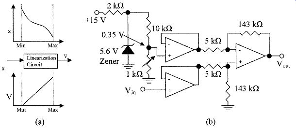
FIG. 1 (a) The input and ideal output of an ideal linearization circuit
and (b) the instrument circuit used for zero and span adjust. This circuit
is used in EXAMPLE 1.
EXAMPLE 1 gives a simple example of adjusting for an offset zero. The sensor output could have varied from 0.7 to 0.35 V as the measured variable changed from low to high, and both the offset and span of the sensor could be temperature sensitive. In this case the circuit shown in FIG. 2 can be used to invert the signal. The 10 k? resistor in the biasing network can be at the same temperature as the sensor and have the same temperature coefficient as the zero offset of the sensor to compensate for zero drift. Span drift or gain can be compensated by a temperature-sensitive resistor in the amplifier feedback. This feedback resistor will also be at the same temperature as the sensor.
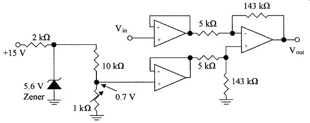
FIG. 2 Instrument sensor compensation circuit.
2.2 Linearization
EXAMPLE 1 shows how to correct for offset. Another problem is nonlinearity in the relation between the measured variable and sensor output. The approach in analog systems and digital systems will be different.
Linearization in analog circuits is difficult unless there is a relatively simple equation to describe the sensor's characteristics. In some applications a much more expensive linear transducer may have to be used due to the inability of analog circuits to linearize the signal conversion. FIG. 3a shows the circuit of a logarithmic amplifier. FIG. 3b shows the variations in characteristics with various resistor values that can be obtained for use in signal linearization. When R2 =8 and R3 = 0, the amplifier has a logarithmic relation between input and output. When R3 is larger than zero the gain is higher at the upper end of the scale, as shown. If R2 is a high value, the effect is to reduce the gain at the lower end of the scale. Multiple feedback paths can be used with non linear elements and resistors to approximate the amplifier characteristics to those of the sensor.
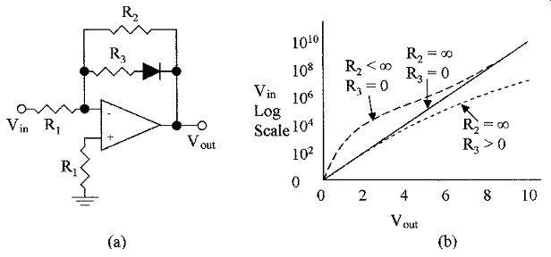
FIG. 3 Nonlinear amplifier (a) circuit and (b) characteristics of
nonlinear circuit with different feedback values.
Linearization in digital circuits can be performed for nonlinear devices by using equations or memory look-up tables. If the relationship between the values of a measured variable and the output of a sensor can be expressed by an equation, the processor can be programmed on the basis of the equation to linearize the data received from the sensor. An example would be a transducer that outputs a current I related to flow rate v by
I = Kv^2 (1)
where K is a constant.
The current numbers from the sensor are converted into binary, where the relationship still holds. In this case, a linear relationship is required between
the current and flow rate. This can be obtained by multiplying the term I by itself, then the resulting number is proportional to v^2 , or the generated number and flow now have a linear relationship. Span and offsets may now require further adjustment.
There are many instances in conversion where there is not an easily definable relationship between variable and transducer outputs and it may be difficult or impossible to write a best fit equation that is adequate for linearization of the variable. In this case, look-up tables are used. The tables correlate transducer output and the true value of the variable, and these values are stored in memory so that the processor can retrieve the true value of the variable from the transducer reading by consulting its look-up tables. This method is extensively used with thermocouples.
2.3 Temperature correction
Sensors are notoriously temperature sensitive, i.e., their output zero as well as span will change with temperature, and in some cases the change is nonlinear.
Variables are also temperature sensitive and require correction. Correction of temperature effects requires a temperature sensitive element to monitor the temperature of the variable and the sensor. The temperature compensation in analog circuits will depend on the characteristics of the sensor used. Because the characteristics of the sensors change from type to type, the correction for each type of sensor will be different. In digital circuits, computers can make the corrections from the sensor and variable characteristics using temperature compensation look-up tables.
Other compensations needed can take the form of filtering to remove unwanted frequencies such as pick up from the 60-Hz line frequency, noise or radio frequency (RF) pickup, dampen out undulations or turbulence to give a steady average reading, correction for time constants, and for impedance matching networks.
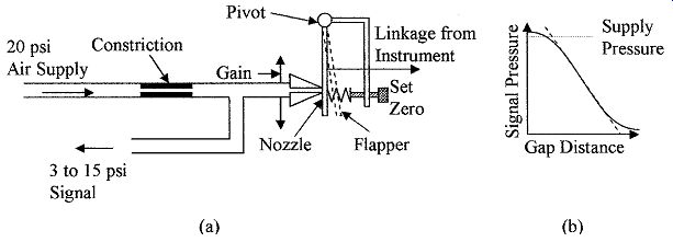
FIG. 4 Illustrates (a) mechanical to pneumatic signal transducer and
(b) the output pressure versus gap distance.
3. Pneumatic Signal Conditioning
Pneumatic signals as well as electrical signals can be used to control actuators. The bourdon tube, capsule, or bellows convert pressure into mechanical motion which can be used for pneumatic control. FIG. 4a shows a pneumatic signal conditioner. Air from a 20-psi regulated supply is fed through a constriction to a nozzle and flapper that controls the pressure output. The flapper is mechanically linked to a bellows. When the variable is at its minimum, the linkage opens the flapper, allowing air to be released. The output pressure to the actuator would then be at its minimum, i.e., 3 psi. As the variable increases, the linkage to the flapper causes it to close and the output pressure increases to 15 psi. This gives a linear output pressure range from 3 to 15 psi (20 to 100 kPa) with linear sensor motion and the pressure variations can be used for actuator control. The set zero adjusts the flapper's position and the nozzle can be moved up and down to give a gain or span control. In some cases the mechanical linkage is reversed so that when the variable is a maximum, the output pressure is 3 psi and 15 psi for the minimum. FIG. 4b shows the relation between the gap distance and the output pressure. The relationship is linear from 3 to 15 psi. Using 3 psi as a minimum gives an additional advantage in that 0 psi indicates a fault condition. Newer systems will use electrical signals in preference to pneumatic signals, as no pressure line, regulator, or compressor is required. Pneumatic control is not compatible with microcontrollers.
4. Visual Display Conditioning
The method of signal conditioning can vary, depending on the destination of the signal. For instance, a local signal for a visual display will not require the accuracy of a signal used for process control. Visual displays are not normally temperature compensated or linearized. They often use mechanical linkages which are subject to wear over time giving a final accuracy between 5 and 10 percent of the reading, i.e., there is little or no conditioning. However, with most of the nonlinear sensors, the scale of the indicator will be nonlinear to give a more accurate indication. These displays are primarily used to give an indication that the system is working within reasonable limits or is within broadly set limits, i.e., tire pressures, air conditioning systems, and the like.
4.1 Direct reading sensors
A few sensors have outputs that are suitable for direct reading at the point of measurement, but the outputs cannot be used for control or transmission. Such devices are sight glasses for level indication, liquid in glass for temperature, a rotameter for flow, hydrometer for density or specific gravity (SG), and possibly a liquid filled U-tube manometer for differential or gauge pressure measurements.
Visual indicators should be clear for ease of reading and the scale well defined.
Rotameters need to be selected for flow rates, fluid density, and their output value should be corrected for temperature variations from look-up tables. Care needs to be taken to ensure that the thermometer bulbs are correctly placed in the fluid for temperature measurement and do not touch the container walls, as this can affect the temperature reading. When measuring liquid levels and liquid and gas pressures, the instrument should have conditioning baffles to minimize pressure and level fluctuations which can introduce uncertainties into the readings.
The Bourdon tube, capsule, or bellows convert pressure into mechanical motion which is well suited for conversion to direct visual indication; the Bourdon tube for instance is normally an integral part of the indicator. FIG. 5a shows a mechanical linkage from a sensor to a direct reading indicator as is normally used for pressure sensing. The Bourdon tube is normally located behind the dial. As the pressure changes the Bourdon tube changes its radius and moves the toothed slider to operate the pointer. The pointer moves over a scale which is graduated in pounds per square inch and so on. These devices are cost effective and are in wide scale use, but are not temperature compensated and the cheaper instruments do not have a zero or span adjustment. More expensive devices may have screw adjustments and a limited temperature range.
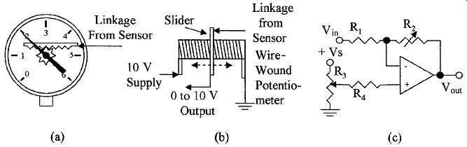
FIG. 5 Mechanical linkage for (a) direct reading indicator, (b) wire-wound
potentiometer, and (c) a simple circuit for use with the potentiometer.
5. Electrical Signal Conditioning
The accuracy of the sensor signal is not only dependent on the sensor characteristics but mainly on the applied conditioning. Many processes require variables to be measured to an accuracy of more than 1 percent over the full range, which means not only very accurate sensing, but also temperature compensation, linearization, zero set, and span adjustment. Temperature compensation is achieved in many sensors by using them in bridge circuits but further compensation may be needed to correct for changes in the variable due to temperature.
Such things as op-amp offset and amplification are affected by supply voltages so that these will have to be regulated and care must be taken with grounding of the system to minimize noise and zero offset. Careful selection is needed in the choice of components. Quality close tolerance components and the use of impedance-matching devices are required to prevent the introduction of errors in conditioning networks.
5.1 Linear sensors
FIG. 5b shows a mechanical linkage from a sensor to the wiper of a potentiometer. In this case the variable is converted into an electrical voltage, giving a voltage output from 0 to10 V. The output voltage can be fed to a voltmeter, converted to a current with an amplifier, or digitized to operate a remote sensing indicator, an actuator, or a signal to a controller. FIG. 5c shows a circuit that could be used for conditioning with set zero and gain control potentiometers. The set zero can be adjusted by R3 to give zero output with minimum input and the span adjusted by R2 to give the required gain. The supply voltage to the amplifier and +Vs to R3 will need to be regulated voltages. However impedance matching devices should be used in instrumentation.
FIG. 6a gives an alternative method of signal conditioning the linear motion output from a bellows into an electrical signal using a linear variable differential transformer (LVDT). The bellows converts the differential pressure between P1 and P2 into linear motion, which changes the position of the core in the LVDT.
FIG. 6b shows a circuit that can be used to condition the electrical signal output from an LVDT. As the output from the transformer is ac, diodes are used to rectify the signal. The signal is then smoothed using a resistor-capacitor (RC) filter, and the two dc levels are fed to an op-amp for comparison. The set zero and span adjustments are not shown.
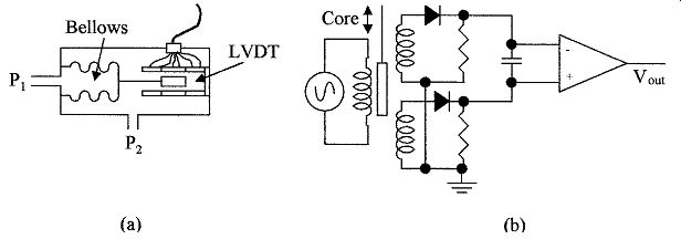
FIG. 6 (a) Differential pressure bellows converting pressure into
an electrical signal using an LVDT and (b) a signal conditioning circuit
for the LVDTs.
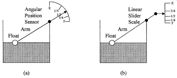
FIG. 7 Scales for a float type angular arm type of sensor (a) radial
and (b) straight line.
5.2 Float sensors
A float is often used for level measurements. The level can be converted into angular or linear motion, but gives a somewhat nonlinear output, as many of us have found with our automotive gas gauge. FIG. 7a shows the relation between fluid level and rotational scale. The scale is cramped at the full end, so that the output from a rotational type potentiometer will give small voltage changes when the container is full, compared to large voltage changes when the container is approaching empty. FIG. 7b shows the relation between fluid level and a linear scale, which is also cramped at the full end, so that in either case the scales are similar.
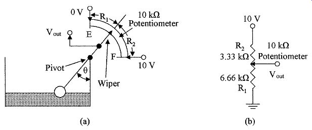
FIG. 8 For use with EXAMPLE 2a shows float connected to a 10-kOhm
potentiometer and (b) 10 k? potentiometer readings at liquid half-full.
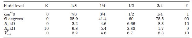
TABLE 1--Resistance Values, Angle, and Vout for Various Liquid Levels
with Float Sensor
From FIG. 8a it is possible to calculate the values of q, R1, R2, and Vout for various liquid levels. These are shown in Table 1.
FIG. 9a shows a plot of the output voltage versus the volume of liquid in the tank from Table 12.1 for the uncompensated curve. The best-fit straight line (dashed) gives an error of about ±15 percent of full scale reading (FSD). To correct the mid-point of the scale for 5 V output when the tank is half full (FIG. 8b), the circuit would require a 6.66-kOhm resistor from the wiper to ground as shown in FIG. 9b (the resistor should be made with the same material as the potentiometer). Table 12.2 gives the liquid levels, resistance values with the potentiometer in parallel with the 6.66 k? resistor, and the output voltage for the circuit in FIG. 9b. The new values are also plotted in FIG. 9a as the compensated curve. The best-fit straight line (dashed) gives an error of less than ±5 percent showing the improved linearity with simple conditioning. The output voltage from the float sensor can also be compensated by the control processor before being fed to other elements in the system.
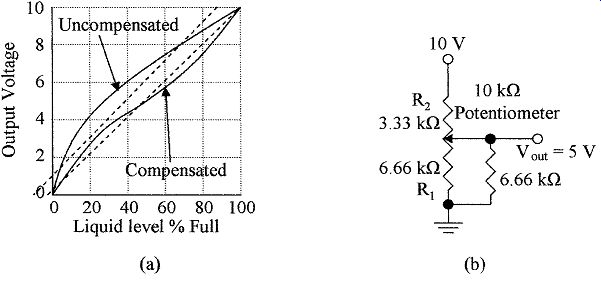
FIG. 9 Characteristic output voltage (a) plotted against liquid level
for an uncompensated and compensated float sensor and (b) the circuit with
a compensated potentiometer.
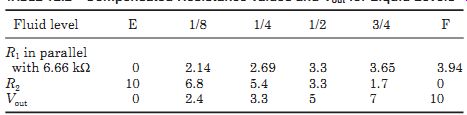
TABLE 2 Compensated Resistance Values and Vout for Liquid Levels
An alternative to the float attached to an arm is a float with a counter balance as shown in FIG. 10a. This arrangement will give a linear scale with liquid level or if a rotary potentiometer is attached to the pointer pivot, the output voltage from the potentiometer will be linear with liquid level as shown in FIG. 10b.
5.3 Strain gauge sensors
Diaphragms use strain gauge or capacitive sensing, the movement being too small to control a pneumatic flapper, slider, or potentiometer. The strain gauge elements are resistors made from copper or nickel particles glued onto a non conducting substrate; semiconductor strain gauges are also available that use the piezoresistive effect.
A strain gauge normally consists of two strain elements mounted at right angles to each other and in close proximity, so that they are both at the same temperature. See FIG. 11a. The gauge is mounted on the diaphragm with one gauge in line with the direction of maximum strain for strain measurement and the other perpendicular to the line of strain, so that it will not sense the strain, and is used to provide temperature compensation and signal conditioning for the strain gauge element when used in a bridge circuit.
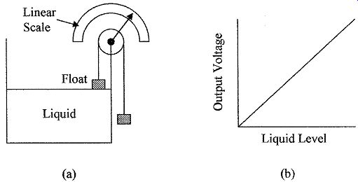
FIG. 10 (a) Float-type sensor with a linear radial scale and (b) output
voltage versus liquid level when the scale is replaced by a potentiometer.
FIG. 11b shows a circuit using the strain gauge. The strain gauge elements are mounted in two arms of the bridge and two resistors, R1 and R2, form the other two arms, R3 and R5 are the conditioning for the zero offset and span, respectively. The output signal from the bridge is amplified and impedance matched, as shown. The strain gauge elements are in opposing arms of the bridge, so that any change in the resistance of the elements due to temperature changes will not affect the balance of the bridge, giving temperature compensation.
More gain and impedance matching stages than shown may be required or an A/D converter will be required to make the signal suitable for transmission. Additional linearization may also be needed; this information can be obtained from the manufacturers' device specifications.
5.4 Capacitive sensors
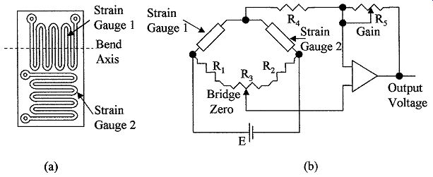
FIG. 11 (a) Configuration for strain gauge elements and (b) Resistive
bridge for signal conditioning of a strain gauge.
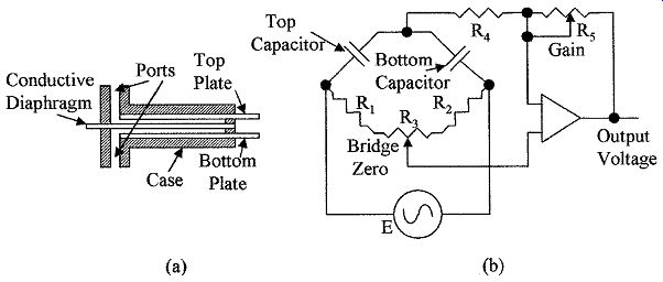
FIG. 12 Illustrates (a) capacitive diaphragm pressure sensor and (b)
an ac bridge for use with a capacitive sensor.
Capacitive sensing devices can use single-ended sensing or differential sensing. With single-ended sensing, capacitance is measured between the diaphragm and a single capacitor plate in close proximity to the diaphragm. Differential sensing can be used when there are capacitor plates on either side of, and in close proximity to, the diaphragm (see FIG. 12a). In differential sensing the two capacitors can be used to form two arms of an ac bridge or switch capacitor techniques can be used. For single ended sensing a fixed reference capacitor can be used.
Capacitive sensing can use ac analog or digital techniques. Microminiature pressure sensors can use piezoresistive strain gauge sensing or capacitive sensing techniques. Being a semiconductor-based technology, the sensor signal is conditioned on the die, i.e., amplified, impedance matched, linearized, and tempera ture compensated.
FIG. 12b shows an ac bridge with offset and span conditioning that can be used with capacitive sensing. Initially, the bridge is balanced for zero offset with potentiometer R3, the output from the bridge is amplified and buffered. The output amplitude can be adjusted by the gain control, R5. The signal will need to be converted to a dc signal and further amplified for transmission.
5.5 Resistance sensors
Resistive temperature detectors (RTD) measure the change in the electrical resistance of a wire-wound resistor with temperature, typically, a platinum resistance element is used with a resistance of about 100 ?. The resistance change can be measured in a bridge circuit, but normally the resistor is driven from a constant current source and the voltage developed across the resistor measured. Care must be taken with these devices to ensure that the current flowing through the devices is low to minimize the temperature changes occur ring due to the internal heating of the resistor. Pulse techniques can be used to prevent internal heating. In this case the current is turned on for a few milliseconds, the voltage measured and then turned off for, say, a second. FIG. 13a shows the simplest connection to the RTD with just two leads, the meter being connected to the current supply leads. The resistance of long leads between the detector and the resistor contribute to measurement error, as the meter is measuring the voltage drop across the current lead resistance and junctions as well as the RTD.
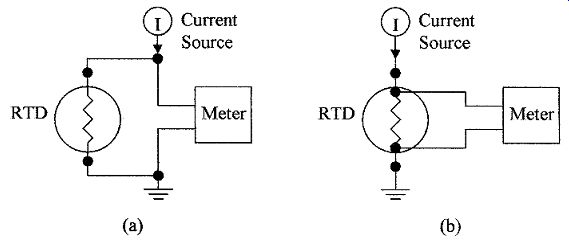
FIG. 13 RTD connections using (a) common supply and meter leads and
connected meter.
FIG. 13b shows a 4-wire connection to an RTD. The meter connects directly to the RTD so that only the voltage drop across the RTD is measured; no error is introduced due to the resistance of the current supply contacts or lead resistance to the RTD. Platinum is the material of choice for an RTD. A linearity of 3.6 percent can be obtained from 0 to 850°C without signal conditioning.
The RTD has a constant current flowing through it giving an offset zero, so that zero level correction and span conditioning are required. Direct connection of the resistive element to the controller will be further discussed in Sect. 13.
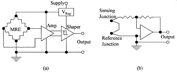
FIG. 14 (a) MRE magnetic field sensing circuit and (b) a thermocouple
signal amplifying circuit.
5.6 Magnetic sensors
Many flow measurements are sensed as differential pressures with the indicator scale graduated in cubic feet per minute, gallons per minute, liters per second, and so forth. Rotating devices, such as the turbine, are used for accurate flow measurements. The devices are simple, do not require conversion to pressure or other medium, have low drag, can be constructed of inert materials that are resistant to corrosion, do not require regular recalibration, and are low maintenance. The pick off is a magnetic sensor such as a Hall effect or an MRE device.
The Hall device gives an electrical impulse every time a blade passes under the sensor, whereas the resistance of the MRE device changes in a changing magnetic field. FIG. 14a shows the circuit used to shape the signal from an MRE into a digital signal. The MRE sensor contains four elements to form a bridge circuit as shown. The Hall or MRE device does not normally require tempera ture compensation as they are being used as switches in digital configurations.
To measure flow rates a window is opened for a known time period. The number of impulses from these devices are counted from which the rate of flow can be calculated. These devices can also be used to measure the total volume in gallons or liters; in this case the number of pulses from the sensors can be counted and divided by the number of pulses per unit volume to give the total volume that has flowed. Some conditioning may be required for the density changes in the liquid with temperature and for high and low flow rates. The conditioning will depend on the requirements of the application and manufacturers' specifications.
5.7 Thermocouple sensors
Thermocouples are connected as shown in FIG. 14b. The sensing junction and the reference junction are connected in series. When the junctions are at the same temperature the voltage output from the junctions is zero, and the output from the amplifier is zero. When the junctions are at different temperatures, there is a differential voltage at the input to the amplifier that is amplified and converted to a temperature reading. To make this an absolute reading the temperature of the reference junction is required. This can be achieved by placing the junction in a constant temperature enclosure, or the temperature of the reference junction can be measured and a correction applied to the output reading of the thermocouple's sensing amplifier. The amount of conditioning required by a thermocouple will depend on its temperature measuring range (see Table 6 , sect. 8).
Its accuracy is 1 to 2 percent over a limited temperature range but needs conditioning (linearizing) if used over its full operating range. The set zero conditioning is a part of the reference temperature correction. Thermocouple voltages can also be sensed directly by the controller using an internal amplifier and then conditioned internally; this is discussed in Sect. 13.
5.8 Other sensors
Piezoelectric sensors are used for sensing force that can be produced by pressure, weight, or acceleration. These devices have high sensitivity but are poor at sensing low-level forces due to offset and drift caused by temperature variations.
Piezoelectric devices are normally packaged with a buffer amplifier and conditioning as shown in Fig. 12b, Sect. 5 but extra gain stages may be needed before trans mission. Any extra conditioning necessary can be obtained from the manufacturers' specifications.
Angular and distance measuring devices are digital in nature so that any conditioning required is done at the controller; only the correct format is needed for transmission.
Bimetallic sensors are temperature-sensing devices that can be used with a mechanical linkage to operate a display directly such as in an oven thermometer but are not accurate enough for linear control applications. Other bimetallic devices operate switches (mercury in glass or mechanical contacts) as simple / ON/OFF devices; such are used in thermostat applications normally without conditioning.
Taguchi, chemical, smoke detectors, and similar types of sensors all require conditioning; the type and extent of the conditioning required depends on the application and manufacturers' specifications and will not be discussed here.
6. A-D Conversion
Many analog signals are converted to digital signals for transmission. In many cases the output from a sensor can be converted directly into a digital signal, such as with capacitive sensors. The value of capacitors can be accurately sensed using digital techniques, eliminating the need for analog amplification, but conditioning of the sensor is still required. Resistive-type devices can also be sensed directly using digital techniques, but again temperature compensation of the sensor is required. However, in the digital domain, all the conditioning can be performed by the processor in the controller, using software or look-up tables.
Summary
This Section introduced signal conditioning and some of the various methods used to linearize signals and the correction needed for zero offset.
The salient points covered were as follows:
1. The methods used to convert the displacement sensor signal into a pneumatic or electrical signals. The transducer used can be a potentiometer, LVDT, or capacitive devices.
2. Linearization of signals, changing operating levels and gain control using non linear analog amplifiers or equations and look-up tables when using digital methods.
3. Pneumatic signal conditioning and system failure detection.
4. Conditioning for direct reading visual displays.
5. Conversion of sensor signals to electrical signal for conditioning.
6. Techniques used in the temperature compensation of strain gauges and other types of devices.
7. Capacitive sensor measurements using ac bridge circuits.
8. The methods used to reduce errors in the measurement of RTD signals.
9. Magnetic sensors are digital in nature and do not require the same type of conditioning as analog devices but can be nonlinear and conditioning of the sensor and material being measured may be required.
Problems
1 Name two magnetic field sensors.
2 What is the difference between a sensor, a transducer, and a converter?
3 Why is it necessary to use signal conditioning on sensor signals?
4 How do pneumatic transducers control pressure?
5 The output voltage from a sensor varies from a minimum of 0.21 V to a maximum of 0.56 V. Draw a circuit to condition the signal so that the output voltage goes from 0 to 10 V. Assume a reference voltage of 10 V, the resistor from the reference is 10 k? and the input resistor to the amplifier is 5 k?.
6 What methods are used to convert mechanical sensor movement into electrical or display signals?
7 What are the methods of providing the reference for a thermocouple?
8 Why are strain gauges normally mounted in pairs at right angles to each other?
9 What types of transducers are used with diaphragm pressure-type sensors?
10 A float sensor using a 27 k? angular position potentiometer is used to measure liquid level in a tank, see FIG. 5. What is the optimum value of resistance between the wiper and ground to compensate for the nonlinearities in the system?
11 What types of analog circuits are used for linearization?
12 What is the effect of a resistor in series with a nonlinear element?
13 What is the effect of a resistor in parallel with a nonlinear element?
14 How is linearization performed in digital circuits?
15 How are temperature corrections made to temperature sensitive sensors?
16 What are the pressure ranges used in pneumatic signal transmissions? Why is zero not used?
17 How can you use a float level sensor to obtain a linear relation between level and electrical output?
18 How is the output from a capacitive type of sensor measured?
19 Why should the meter contacts to an RTD be as close to the measuring element as possible?
20 Which types of sensors are suitable for direct line of sight reading but are hard to use with a transducer?
Related Articles -- Top of Page -- Home