AMAZON multi-meters discounts AMAZON oscilloscope discounts
Objectives
This section will help you understand the units used in pressure measurements and become familiar with the most common methods of using the various pressure measurement standards.
Discussed in this section are:
_ The terms -- pressure, specific weight, specific gravity (SG), and buoyancy
_ The difference between atmospheric, absolute, gauge, and differential pres sure values
_ Various pressure units in use, i.e., British units versus SI (metric) units
_ Various types of pressure measuring devices
_ Difference in static, dynamic, and impact pressures
_ Laws applied to pressure
_ Application considerations
1. Introduction
Pressure is the force exerted by gases and liquids due to their weight, such as the pressure of the atmosphere on the surface of the earth and the pressure containerized liquids exert on the bottom and walls of a container.
Pressure units are a measure of the force acting over a specified area. It is most commonly expressed in pounds per square inch (psi), sometimes pounds per square foot (psf) in English units, or pascals (Pa or kPa) in metric units.
(Eqn. 1) Pressure= force/area
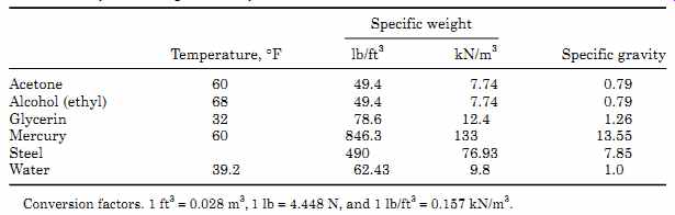
TABLE 1 Specific Weights and Specific Gravities of Some Common Materials
2. Basic Terms
Density r is defined as the mass per unit volume of a material, i.e., pound (slug) per cubic foot (lb (slug)/ft^3 ) or kilogram per cubic meter (kg/m^3 ).
Specific weight g is defined as the weight per unit volume of a material, i.e., pound per cubic foot (lb/ft^3 ) or newton per cubic meter (N/m^3 ).
Specific gravity of a liquid or solid is a dimensionless value since it is a ratio of two measurements in the same unit. It is defined as the density of a material divided by the density of water or it can be defined as the specific weight of the material divided by the specific weight of water at a specified temperature. The specific weights and specific gravities of some common materials are given in TABLE 1. The specific gravity of a gas is its density/specific weight divided by the density/specific weight of air at 60°F and 1 atmospheric pressure (14.7 psia).
In the SI system the density in g/cm^3 or Mg/m^3 and SG have the same value.
Static pressure is the pressure of fluids or gases that are stationary or not in motion (see FIG. 1). Point A is considered as static pressure although the fluid above it is flowing.
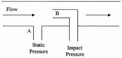
FIG. 1 Illustration of static, dynamic, and impact pressures.
Dynamic pressure is the pressure exerted by a fluid or gas when it impacts on a surface or an object due to its motion or flow. In FIG. 1 the dynamic pressure is (B - A).
Impact pressure (total pressure) is the sum of the static and dynamic pressures on a surface or object. Point B in FIG. 1 depicts the impact pressure.
3. Pressure Measurement
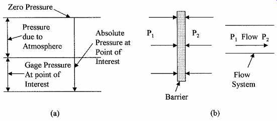
FIG. 2 Illustration of (a) gauge pressure versus absolute pressure
and (b) delta or differential pressure.
There are six terms applied to pressure measurements. They are as follows:
Total vacuum-which is zero pressure or lack of pressure, as would be experienced in outer space.
Vacuum is a pressure measurement made between total vacuum and normal atmospheric pressure (14.7 psi).
Atmospheric pressure is the pressure on the earth's surface due to the weight of the gases in the earth's atmosphere and is normally expressed at sea level as 14.7 psi or 101.36 kPa. It is however, dependant on atmospheric conditions.
The pressure decreases above sea level and at an elevation of 5000 ft drops to about 12.2 psi (84.122 kPa).
Absolute pressure is the pressure measured with respect to a vacuum and is expressed in pounds per square inch absolute (psia).
Gauge pressure is the pressure measured with respect to atmospheric pressure and is normally expressed in pounds per square inch gauge (psig). FIG. 2a shows graphically the relation between atmospheric, gauge, and absolute pressures.

TABLE 2 Pressure Conversions
Differential pressure is the pressure measured with respect to another pres sure and is expressed as the difference between the two values. This would rep resent two points in a pressure or flow system and is referred to as the delta p or ?p. FIG. 2b shows two situations, where differential pressure exists across a barrier and between two points in a flow system.
4. Pressure Formulas
Hydrostatic pressure is the pressure in a liquid. The pressure increases as the depth in a liquid increases. This increase is due to the weight of the fluid above the measurement point. The pressure is given by p = gh (Eqn. 2)
where ...
p = pressure in pounds per unit area or pascals
g = the specific weight (lb/ft^3 in English units or N/m^3 in SI units)
h = distance from the surface in compatible units (ft, in, cm, m, and so on)
Example 4 --- What is the gauge pressure in (a) kilopascals and (b) newtons per square centimeter at a distance 1 m below the surface in water?
(a) p = 100 cm/m/10.2 cm/kPa = 9.8 kPa
(b) p = 9.8 N/m^2 = 9.8/10,000 N/cm^2 = 0.98 × 10^-3 N/cm^2
The pressure in this case is the gauge pressure, i.e., kPa(g). To get the total pressure, the pressure of the atmosphere must be taken into account. The total pressure (absolute) in this case is 9.8 + 101.3 = 111.1 kPa(a). The g and a should be used in all cases to avoid confusion. In the case of pounds per square inch and pounds per square foot this would become pounds per square inch gauge and pounds per square foot gauge, or pounds per square inch absolute and pounds per square foot absolute. Also it should be noted that if glycerin was used instead of water the pressure would have been 1.26 times higher, as its specific gravity is 1.26.
Example 5---What is the specific gravity of mercury if the specific weight of mercury is 846.3 lb/ft^3
? SG = 846.3/62.4 = 13.56
Head is sometimes used as a measure of pressure. It is the pressure in terms of a column of a particular fluid, i.e., a head of 1 ft of water is the pressure that would be exerted by a 1 ft. tall column of water, that is, 62.4 psfg, or the pressure exerted by 1 ft head of glycerin would be 78.6 psfg.
Example 6---What is the pressure at the base of a water tower which has 50 ft of head?
p = 62.4 lb/ft^3 × 50 ft = 3120 psfg = 3120 psf/144 ft^2/in^2 = 21.67 psig
The hydrostatic paradox states that the pressure at a given depth in a liquid is independent of the shape of the container or the volume of liquid contained.
The pressure value is a result of the depth and density. FIG. 3a shows various shapes of tanks. The total pressure or forces on the sides of the container depend on its shape, but at a specified depth. The pressure is given by Eq. (Eqn. 2).
Buoyancy is the upward force exerted on an object immersed or floating in a liquid. The weight is less than it is in air due to the weight of the displaced fluid.
The upward force on the object causing the weight loss is called the buoyant force and is given by
B = gV (Eqn. 3) where
B = buoyant force (lb)
g = specific weight (lb/ft^3 )
V = volume of the liquid displaced (ft^3 )
If working in SI units, B is in newtons, g in newton per cubic meter, and V in cubic meters.
FIG. 3 Diagrams demonstrating (a) the hydrostatic paradox and (b) buoyancy.
In FIG. 3b, a, b, c, and d are of the same size. The buoyancy forces on a and c are the same although their depth is different. There is no buoyancy force on d as the liquid cannot get under it to produce the force. The buoyancy force on b is half of that on a and c, as only half of the object is submersed.
Example 7 --- What is the buoyant force on a wooden cube with 3-ft sides floating in water, if the block is half submerged?
Example 8 --- What is the apparent weight of a 3-m^3 block of steel totally immersed in glycerin?
Weight of steel in air = 3 × 76.93 kN = 230.8 kN
Buoyancy force on steel = 3 × 12.4 kN = 37.2 kN
Apparent weight = 230.8 - 37.2 = 193.6 kN (19.75 Mg)
Pascal's law states that the pressure applied to an enclosed liquid (or gas) is transmitted to all parts of the fluid and to the walls of the container. This is demonstrated in the hydraulic press in FIG. 4. A force FS, exerted on the small piston (ignoring friction), will exert a pressure in the fluid which is given by (Eqn. 4)
...where ... AS is the cross-sectional area of the smaller piston.
Since the pressure is transmitted through the liquid to the second cylinder (Pascal's law), the force on the larger piston (FL) is given by:
FL = pAL (Eqn. 5)
... where ...AL is the cross-sectional area of the large piston (assuming the pistons are at the same level), from which (Eqn. 6)
It can be seen that the force FL is magnified by the ratio of the piston areas.
This principle is used extensively in hoists, hydraulic equipment, and the like.
Example 9 --- In FIG. 4, if the area of the small piston AS is 0.3 m^2 and the area of the large piston AL is 5 m^2 , what is the force FL on the large piston, if the force FS on the small piston is 85 N?
A vacuum is very difficult to achieve in practice. Vacuum pumps can only approach a true vacuum. Good small volume vacuums, such as in a barometer, can be achieved. Pressures less than atmospheric pressure are often referred to as "negative gauge" and are indicated by an amount below atmospheric pres sure, for example, 5 psig would correspond to 9.7 psia (assume atm = 14.7 psia).
5. Measuring Instruments
5.1 Manometers
Manometers are good examples of pressure measuring instruments, though they are not as common as they used to be because of the development of new, smaller, more rugged, and easier to use pressure sensors.
U-tube manometers consist of U-shaped glass tubes partially filled with a liquid.
When there are equal pressures on both sides, the liquid levels will correspond to the zero point on a scale as shown in FIG. 5a. The scale is graduated in pressure units. When a pressure is applied to one side of the U-tube that is higher than on the other side, as shown in FIG. 5b, the liquid rises higher in the lower pressure side, so that the difference in the heights of the two columns of liquid compensates for the difference in pressure, as in Eq. (Eqn. 2). The pressure difference is given by PR - PL = g × difference in height of the liquid in the columns (Eqn. 7) where g is the specific weight of the liquid in the manometer.
Inclined manometers were developed to measure low pressures. The low pressure arm is inclined, so that the fluid has a longer distance to travel than in a vertical tube for the same pressure change. This gives a magnified scale as shown in FIG. 6a.
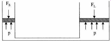
FIG. 4 Diagram of a hydraulic press.
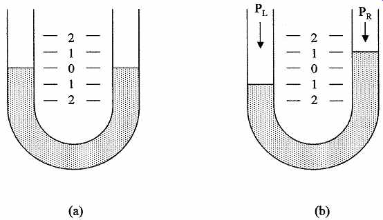
FIG. 5 Simple U-tube manometers with (a) no differential pressure and
(b) higher pres sure on the left side.
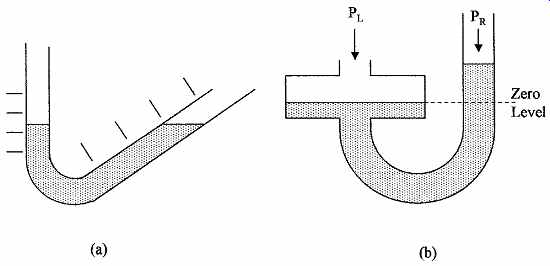
FIG. 6 Other types of manometers are the (a) inclined-tube manometer
and (b) well type manometer.
Well manometers are alternatives to inclined manometers for measuring low pressures using low-density liquids. In the well manometer, one leg has a much larger diameter than the other leg, as shown in FIG. 6b. When there is no pres sure difference the liquid levels will be at the same height for a zero reading.
An increase in the pressure in the larger leg will cause a larger change in the height of the liquid in the smaller leg. The pressure across the larger area of the well must be balanced by the same volume of liquid rising in the smaller leg. The effect is similar to the balance of pressure and volume in hydraulic jacks.
Example 10 --- The liquid in a well manometer has a specific weight of 40 lb/ft^3. How far will the liquid rise in the smaller leg, if the pressure in the larger leg is 1.5 lb/ft^2 higher than in the smaller leg?
Example 11 --- The liquid in a manometer has a density of 850 kg/m^3. What will be the difference in the liquid levels in the manometer tubes, if the differential pressure between the tubes is 5.2 kPa?
5.2 Diaphragms, capsules, and bellows
Gauges are a major group of pressure sensors that measure pressure with respect to atmospheric pressure. Gauge sensors are usually devices that change their shape when pressure is applied. These devices include diaphragms, capsules, bellows, and Bourdon tubes.
A diaphragm consists of a thin layer or film of a material supported on a rigid frame and is shown in FIG. 8a. Pressure can be applied to one side of the film for gauge sensing or pressures can be applied to both sides of the film for differential or absolute pressure sensing. A wide range of materials can be used for the sensing film, from rubber to plastic for low-pressure devices, silicon for medium pressures, to stainless steel for high pressures. When pressure is applied to the diaphragm, the film distorts or becomes slightly spherical. This movement can be sensed using a strain gauge, piezoelectric, or changes in capacitance techniques (older techniques included magnetic and carbon pile devices). The deformation in the above sensing devices uses transducers to give electrical signals.
Of all these devices the micromachined silicon diaphragm is the most commonly used industrial pressure sensor for the generation of electrical signals.
A silicon diaphragm uses silicon, which is a semiconductor. This allows a strain gauge and amplifier to be integrated into the top surface of the silicon structure after the diaphragm was etched from the back side. These devices have built-in temperature-compensated piezoelectric strain gauge and amplifiers that give a high output voltage (5 V FSD [volt full scale reading or deflection]). They are very small, accurate (2 percent FSD), reliable, have a good temperature operating range, are low cost, can withstand high overloads, have good longevity, and are unaffected by many chemicals. Commercially made devices are available for gauge, differential, and absolute pressure sensing up to 200 psi (1.5 MPa). This range can be extended by the use of stainless steel diaphragms to 100,000 psi (700 MPa).
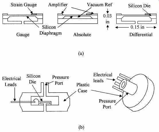
FIG. 7 Cross section of (a) various types of microminiature silicon
pressure sensor die and (b) a packaged microminiature gauge sensor.
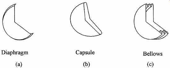
FIG. 8 Various types of pressure-sensing elements: (a) diaphragm, (b)
capsule, and (c) bellows.
FIG. 7a shows the cross sections of the three configurations of the silicon chips (sensor dies) used in microminiature pressure sensors, i.e., gauge, absolute, and differential. The given dimensions illustrate that the sensing elements are very small. The die is packaged into a plastic case (about 0.2 in thick × 0.6 in diameter).
A gauge assembly is shown in FIG. 7b. The sensor is used in blood pressure monitors and many industrial applications, and is extensively used in automotive pressure-sensing applications, i.e., manifold air pressure, barometric air pressure, oil, transmission fluid, break fluid, power steering, tire pressure and the like.
Capsules are two diaphragms joined back to back, as shown in FIG. 8b.
Pressure can be applied to the space between the diaphragms forcing them apart to measure gauge pressure. The expansion of the diaphragm can be mechanically coupled to an indicating device. The deflection in a capsule depends on its diameter, material thickness, and elasticity. Materials used are phosphor bronze, stainless steel, and iron nickel alloys. The pressure range of instruments using these materials is up to 50 psi (350 kPa). Capsules can be joined together to increase sensitivity and mechanical movement.
Bellows are similar to capsules, except that the diaphragms instead of being joined directly together, are separated by a corrugated tube or tube with convolutions, as shown in FIG. 8c. When pressure is applied to the bellows it elongates by stretching the convolutions and not the end diaphragms. The materials used for the bellows type of pressure sensor are similar to those used for the capsule, giving a pressure range for the bellows of up to 800 psi (5 MPa). Bellows devices can be used for absolute and differential pressure measurements.
Differential measurements can be made by connecting two bellows mechanically, opposing each other when pressure is applied to them, as shown in FIG. 9a.
When pressures P1 and P2 are applied to the bellows a differential scale reading is obtained. FIG. 9b shows a bellows configured as a differential pres sure transducer driving a linear variable differential transformer (LVDT) to obtain an electrical signal, P2 could be the atmospheric pressure for gauge measurements. The bellows is the most sensitive of the mechanical devices for low pressure measurements, i.e., 0 to 210 kPa.
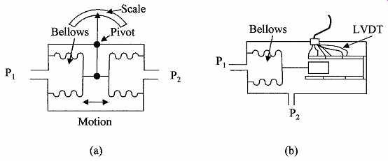
FIG. 9 Differential bellows pressure gauges for (a) direct scale reading
and (b) as a pressure transducer.
5.3 Bourdon tubes
Bourdon tubes are hollow, cross-sectional beryllium, copper, or steel tubes, shaped into a three quarter circle, as shown in FIG. 10a. They may be rectangular or oval in cross section, but the operating principle is that the outer edge of the cross section has a larger surface than the inner portion. When pressure is applied, the outer edge has a proportionally larger total force applied because of its larger surface area, and the diameter of the circle increases. The walls of the tubes are between 0.01 and 0.05 in thick. The tubes are anchored at one end so that when pressure is applied to the tube, it tries to straighten and in doing so the free end of the tube moves. This movement can be mechanically coupled to a pointer, which when calibrated, will indicate pressure as a line of sight indicator, or it can be coupled to a potentiometer to give a resistance value proportional to the pressure for electrical signals. FIG. 10b shows a helical pressure tube. This configuration is more sensitive than the circular Bourdon tube. The Bourdon tube dates from the 1840s. It is reliable, inexpensive, and one of the most common general purpose pressure gauges.
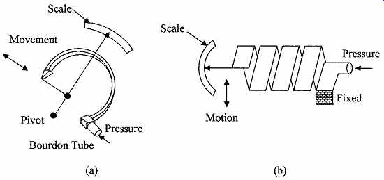
FIG. 10 Pressure sensors shown are (a) the Bourdon tube and (b) the
helical Bourdon tube.
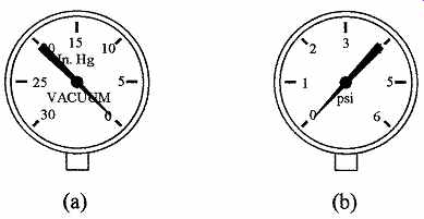
FIG. 11 Bourdon-tube type pressure gauges for (a) negative and (b)
positive pressures.
Bourdon tubes can withstand overloads of up to 30 to 40 percent of their maximum rated load without damage, but if overloaded may require recalibration.
The tubes can also be shaped into helical or spiral shapes to increase their range. The Bourdon tube is normally used for measuring positive gauge pressures, but can also be used to measure negative gauge pressures. If the pres sure on the Bourdon tube is lowered, then the diameter of the tube reduces. This movement can be coupled to a pointer to make a vacuum gauge. Bourdon tubes can have a pressure range of up to 100,000 psi (700 MPa). FIG. 11 shows the Bourdon-tube type of pressure gauge when used for measuring negative pres sure (vacuum) (a) and positive pressure (b). Note the counterclockwise movement in (a) and the clockwise movement in (b).
5.4 Other pressure sensors
Barometers are used for measuring atmospheric pressure. A simple barometer is the mercury barometer shown in FIG. 12a. It is now rarely used due to its fragility and the toxicity of mercury. The aneroid (no fluid) barometer is favored for direct reading (bellows in FIG. 9 or helical Bourdon tube in FIG. 10b) and the solid-state absolute pressure sensor for electrical outputs.
A piezoelectric pressure gauge is shown in FIG. 12b. Piezoelectric crystals pro duce a voltage between their opposite faces when a force or pressure is applied to the crystal. This voltage can be amplified and the device used as a pressure sensor.
Capacitive devices use the change in capacitance between the sensing diaphragm and a fixed plate to measure pressure. Some micromachined silicon pressure sensors use this technique in preference to a strain gauge. This technique is also used in a number of other devices to accurately measure any small changes in diaphragm deformation.
5.5 Vacuum instruments
Vacuum instruments are used to measure pressures less than atmospheric pres sure. The Bourdon tube, diaphragms, and bellows can be used as vacuum gauges, but measure negative pressures with respect to atmospheric pressure.
The silicon absolute pressure gauge has a built-in low-pressure reference, so it is calibrated to measure absolute pressures. Conventional devices can be used down to 20 torr (5 kPa). The range can be extended down to about 1 torr with special sensing devices.
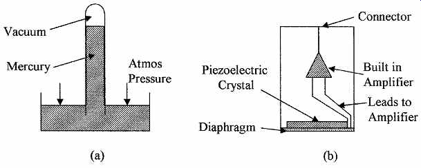
FIG. 12 Diagram of (a) barometer and (b) piezoelectric sensing element.
The Pirani gauge and special setups using thermocouples can measure vacuums down to about 5 torr. These methods are based on the relation of heat conduction and radiation from a heating element to the number of gas molecules per unit volume in the low-pressure region, which determines the pressure.
Ionization gauges can be used to measure pressures down to about 2 torr. The gas is ionized with a beam of electrons and the current is measured between two electrodes in the gas. The current is proportional to the number of ions per unit volume, which is also proportional to the gas pressure.
McLeod gauge is a device set up to measure very low pressures, i. e., from 1 to 50 torr. The device compresses the low-pressure gas so that the increased pres sure can be measured. The change in volume and pressure can then be used to calculate the original gas pressure, providing that the gas does not condense.
6. Application Considerations
When installing pressure sensors, care should be taken to select the correct pres sure sensor for the application.
6.1 Selection
Pressure-sensing devices are chosen for pressure range, overload requirements, accuracy, temperature operating range, line-of-sight reading, or electrical signal, and response time. In some applications there are other special requirements.
Parameters, such as hystersis and stability, should be obtained from the manufacturers' specifications. For most industrial applications reading positive pressures, the Bourdon tube is a good choice for direct visual readings and the silicon pressure sensor for the generation of electrical signals. Both types of devices have commercially available sensors to measure from a few pounds per square inch pressure FSD up to 10,000 psi (700 MPa) FSD. TABLE 3 gives a comparison of the two types of devices.
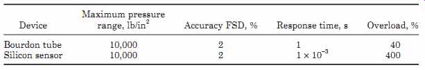
TABLE 3 Comparison of Bourdon Tube Sensor and Silicon Sensor
TABLE 4 lists the operating range for several types of pressure sensors.
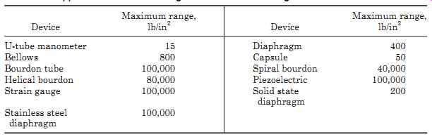
TABLE 4 Approximate Pressure Ranges for Pressure-Sensing Devices
6.2 Installation
The following should be taken into consideration when installing pressure sensing devices.
1. Distance between sensor and source should be kept to a minimum.
2. Sensors should be connected via valves for ease of replacement.
3. Over-range protection devices should be included at the sensor.
4. To eliminate errors due to trapped gas in sensing liquid pressures, the sensor should be located below the source.
5. To eliminate errors due to trapped liquid in sensing gas pressures, the sensor should be located above the source.
6. When measuring pressures in corrosive fluids and gases, an inert medium is necessary between the sensor and the source or the sensor must be corrosion resistant.
7. The weight of the liquid in the connection line of a liquid pressure sensing device located above or below the source will cause errors in the zero, and a correction must be made by the zero adjustment, or otherwise compensated for in measurement systems.
8. Resistance and capacitance can be added to electron circuits to reduce pres sure fluctuations and unstable readings.
6.3 Calibration
Pressure-sensing devices are calibrated at the factory. In cases where a sensor is suspect and needs to be recalibrated, the sensor can be returned to the factory for recalibration, or it can be compared to a known reference. Low-pressure devices can be calibrated against a liquid manometer. High-pressure devices can be calibrated with a dead-weight tester. In a dead-weight tester the pressure to the device under test is created by weights on a piston. High pressures can be accurately reproduced.
Summary
Pressure measurement standards in both English and SI units were discussed in this section. Pressure formulas and the types of instruments and sensors used in pressure measurements were given.
The main points discussed were:
1. Definitions of the terms and standards used in pressure measurements, both gauge and absolute pressures.
2. English and SI pressure measurement units and the relation between the two as well as atmospheric, torr, and millibar standards.
3. Pressure laws and formulas used in hydrostatic pressure measurements and buoyancy together with examples.
4. The various types of instruments including manometers, diaphragms, and micromachined pressure sensors. Various configurations for use in absolute and differential pressure sensing in both liquid and gas pressure measurements.
5. In the application section, the characteristics of pressure sensors were com pared, and the considerations that should be made when installing pressure sensors were given.
Problems:
1. A tank is filled with pure water. If the pressure at the bottom of the tank is 17.63 psig, what is the depth of the water?
2. What is the pressure on an object at the bottom of a fresh water lake if the lake is 123 m deep?
3. An instrument reads 1038 psf. If the instrument was calibrated in kilopascals, what would it read?
4. What will be the reading of a mercury barometer in centimeters if the atmospheric pressure is 14.75 psi?
5. A tank 2.2 ft × 3.1 ft × 1.79 ft weighs 1003 lb when filled with a liquid. What is the specific gravity of the liquid if the empty tank weighs 173 lb?
6. An open tank 3.2 m wide by 4.7 m long is filled to a depth of 5.7 m with a liquid whose SG is 0.83. What is the absolute pressure on the bottom of the tank in kilopascals?
7. Two pistons connected by a pipe are filled with oil. The larger piston has 3.2 ft diameter and has a force of 763 lb applied to it. What is the diameter of the smaller piston if it can support a force of 27 lb?
8. A block of wood with a density of 35.3 lb/ft^3 floats in a liquid with three-fourths of its volume submersed. What is the specific gravity of the liquid?
9. A 15.5-kg mass of copper has an apparent mass of 8.7 kg in oil whose SG is 0.77.
What is the volume of the copper and its specific weight?
10. A dam is 283 m high when it is full of water. What is the pounds per square inch absolute at the bottom of the reservoir?
11. A liquid has a SG of 7.38. What is its specific weight in pound per cube foot and kilogram per cubic meter?
12. What is the equivalent of 25, 49, and 83 kPa in pounds per square inch?
13. The cabin pressure in a spacecraft is maintained at 14.3 psia. What will be the force on a window 2.9 ft wide and 1.7 ft high when the craft is in outer space?
14. A U-tube manometer uses glycerin as the measuring fluid. What will be the differential pressure if the distance between the levels of glycerin is 10^3 in?
15. An open tank contains 1.9 m of water floating on 10.3 cm of mercury. What is the pressure in pounds per square foot absolute on the bottom of the tank?
16. Oil (SG = 0.93) is pumped from a well. If the pump is 11.7 ft above the surface of the oil, what pressure must the pump be able to generate to lift the oil up to the pump?
17. A piston 8.7-in diameter has a pressure of 3.7 kPa on its surface. What force in SI units is applied to the piston?
18. The water pressure at the base of a water tower is 107.5 psi. What is the head of water?
19. AU-tube manometer reads a pressure of 270 torr. What is the pressure in pounds per square inch absolute?
20. Each of the three circular containers in Fig. 13 contain a liquid with a SG of 1.37.
What is the pressure in pascal gauge acting on the base of each container and the weight of liquid in each container?
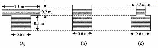
FIG. 13 Figure for use with Prob. 20.
Related Articles -- Top of Page -- Home