AMAZON multi-meters discounts AMAZON oscilloscope discounts
Objectives
This Section will help you understand the units used in level measurements and become familiar with the most common methods of using the various level standards.
Topics discussed in this Section are as follows:
_ The formulas used in level measurements
_ The difference between direct and indirect level measuring devices
_ The difference between continuous and single-point measurements
_ The various types of instruments available for level measurements
_ Application of the various types of level sensing devices
Most industrial processes use liquids such as water, chemicals, fuel, and the like, as well as free flowing solids (powders and granular materials). These materials are stored in containers ready for on-demand use. It is, however, imperative to know the levels and remaining volumes of these materials so that the containers can be replenished on an as needed basis to avoid the cost of large volume storage.
1 Introduction
This Section discusses the measurement of the level of liquids and free flowing solids in containers. The detector is normally sensing the interface between a liquid and a gas, a solid and a gas, a solid and a liquid, or possibly the interface between two liquids. Sensing liquid levels fall into two categories; firstly, single point sensing and secondly, continuous level monitoring. In the case of single point sensing the actual level of the material is detected when it reaches a predetermined level, so that the appropriate action can be taken to prevent overflowing or to refill the container.
Continuous level monitoring measures the level of the liquid on an uninterrupted basis. In this case the level of the material will be constantly monitored and hence, the volume can be calculated if the cross-sectional area of the container is known.
Level measurements can be direct or indirect; examples of these are using a float technique or measuring pressure and calculating the liquid level. Free flowing solids are dry powders, crystals, rice, grain and so forth.
2 Level Formulas
Pressure is often used as an indirect method of measuring liquid levels. Pressure increases as the depth increases in a fluid. The pressure is given by
?p = g ?h (eqn. 1)
where ?p = change in pressure
g = specific weight
?h = depth
Note the units must be consistent, i.e., pounds and feet, or newtons and meters.
Buoyancy is an indirect method used to measure liquid levels. The level is deter mined using the buoyancy of an object partially immersed in a liquid. The buoyancy B or upward force on a body in a liquid can be calculated from the equation
B = g × area × d (eqn. 2)
where area is the cross-sectional area of the object and d is the immersed depth of the object.
The liquid level is then calculated from the weight of a body in a liquid WL, which is equal to its weight in air (WA - B), from which we get
(eqn. 3)
The weight of a container can be used to calculate the level of the material in the container. In FIG. 1a the volume V of the material in the container is given by
V = area × depth = pr 2 × d (eqn. 4)
where r is the radius of the container and d is the depth of the material.
The weight of material W in a container is given by
W = gV (eqn. 5)
Capacitive probes can be used in nonconductive liquids and free flowing solids for level measurement. Many materials, when placed between the plates of a capacitor, increase the capacitance by a factor m called the dielectric constant of the material. For instance, air has a dielectric constant of 1 and water 80.
FIG. 1b shows two capacitor plates partially immersed in a nonconductive liquid. The capacitance (Cd) is given by (eqn. 6)
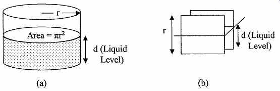
FIG. 1 Shows the relation between (a) volume of liquid and the cross-
sectional area and the liquid depth and (b) liquid level, plate capacitance,
and a known dielectric constant in a nonconducting liquid.
where Ca = capacitance with no liquid
m = dielectric constant of the liquid between the plates
r = height of the plates
d = depth or level of the liquid between the plates
The dielectric constants of some common liquids are given in Table 1; there are large variations in dielectric constant with temperature so that temperature correction may be needed. In Eq. (eqn. 6) the liquid level is given by (eqn. 7)
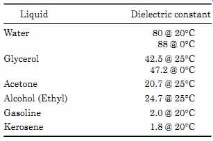
TABLE 1 Dielectric Constant of Some Common Liquids
3 Level Sensing Devices
There are two categories of level sensing devices. They are direct sensing, in which case the actual level is monitored, and indirect sensing where a property of the liquid such as pressure is sensed to determine the liquid level.
3.1 Direct level sensing
Sight glass (open end/differential) or gauge is the simplest method for direct visual reading. As shown in FIG. 2 the sight glass is normally mounted vertically adjacent to the container. The liquid level can then be observed directly in the sight glass. The container in FIG. 2a is closed. In this case the ends of the glass are connected to the top and bottom of the tank, as would be used with a pressurized container (boiler) or a container with volatile, flammable, hazardous, or pure liquids. In cases where the tank contains inert liquids such as water and pressurization is not required, the tank and sight glass can both be open to the atmosphere as shown in FIG. 2b. The top of the sight glass must have the same pressure conditions as the top of the liquid or the liquid levels in the tank and sight glass will be different. In cases where the sight glass is excessively long, a second inert liquid with higher density than the liquid in the container can be used in the sight glass (see FIG. 2c). Allowance must be made for the difference in the density of the liquids. If the glass is stained or reacts with the containerized liquid the same approach can be taken or a different material can be used for the sight glass. Magnetic floats can also be used in the sight glass so that the liquid level can be monitored with a magnetic sensor such as a Hall effect device.
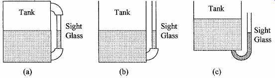
FIG. 2 Various configurations of a sight glass to observe liquid levels
(a) pressurized or closed container, (b) open container, and (c) higher
density sight glass liquid.
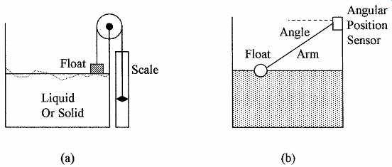
FIG. 3 Methods of measuring liquid levels using (a) a simple float
with level indicator on the outside of the tank and (b) an angular arm float.
Floats (angular arm or pulley) are shown in FIG. 3. The figure shows two types of simple float sensors. The float material is less dense than the density of the liquid and floats up and down on top of the material being measured.
In FIG. 3a a float with a pulley is used; this method can be used with either liquids or free flowing solids. With free flowing solids, agitation is sometimes used to level the solids. An advantage of the float sensor is that it is almost independent of the density of the liquid or solid being monitored. If the surface of the material being monitored is turbulent, causing the float reading to vary excessively, some means of damping might be used in the system. In FIG. 3b a ball float is attached to an arm; the angle of the arm is measured to indicate the level of the material (an example of the use of this type of sensor is the monitoring of the fuel level in the tank of an automobile). Although very simple and cheap to manufacture, the disadvantage of this type of float is its nonlinearity as shown by the line of sight scale in FIG. 4a. The scale can be replaced with a potentiometer to obtain an electrical signal that can be linearized for industrial use.
FIG. 4b shows an alternative method of using pulleys to obtain a direct visual scale that can be replaced by a potentiometer to obtain a linear electrical output with level.
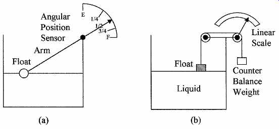
FIG. 4 Scales used with float level sensors (a) nonlinear scale with
angular arm float and (b) linear scale with a pulley type of float.
A displacer with force sensing is shown in FIG. 5a. This device uses the change in the buoyant force on an object to measure the changes in liquid level.
The displacers must have a higher specific weight than that of the liquid level being measured and have to be calibrated for the specific weight of the liquid.
A force or strain gauge measures the excess weight of the displacer. There is only a small movement in this type of sensor compared to a float sensor.
The buoyant force on a cylindrical displacer shown in FIG. 5b using Eq. (eqn. 2) is given by
(eqn. 8)
where:
g = specific weight of the liquid
d = float diameter
L = length of the displacer submerged in the liquid
The weight as seen by the force sensor is given by
Weight on force sensor = weight of displacer - F (eqn. 9)
It should be noted that the units must be in the same measurement system and the liquid must not rise above the top of the displacer or the displacer must not touch the bottom of the container.
Example 1 A displacer with a diameter of 8 in is used to measure changes in water level. If the water level changes by 1 ft what is the change in force sensed by the force sensor?
From Eq. (eqn. 9)
Change in force = (weight of dispenser - F1) - (weight of dispenser - F2)
= F2 - F1
From Eq. (eqn. 8)
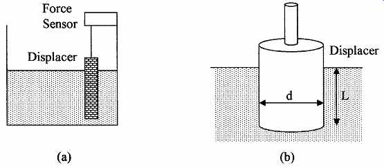
FIG. 5 Displacer with a force sensor for measuring liquid level by
(a) observing the loss of weight of the displacer due to the buoyancy forces
of the displaced liquid and (b) dispenser dimensions.
Example 2 A 3.5-cm diameter displacer is used to measure acetone levels. What is the change in force sensed if the liquid level changes by 52 cm? Probes for measuring liquid levels fall into three categories, i.e., conductive, capacitive, and ultrasonic.
Conductive probes are used for single-point measurements in liquids that are conductive and nonvolatile as a spark can occur. Conductive probes are shown in FIG. 6a. Two or more probes as shown can be used to indicate set levels. If the liquid is in a metal container, the container can be used as the common probe.
When the liquid is in contact with two probes the voltage between the probes causes a current to flow indicating that a set level has been reached. Thus, probes can be used to indicate when the liquid level is low and to operate a pump to fill the container. Another or a third probe can be used to indicate when the tank is full and to turn off the filling pump.
Capacitive probes are used in liquids that are nonconductive and have a high m and can be used for continuous level monitoring. The capacitive probe shown in FIG. 6b consists of an inner rod with an outer shell; the capacitance is measured between the two using a capacitance bridge. In the portion out of the liquid, air serves as the dielectric between the rod and outer shell. In the immersed section, the dielectric is that of the liquid that causes a large capacitive change, if the tank is made of metal it can serve as the outer shell. The capacitance change is directly proportional to the level of the liquid. The dielectric constant of the liquid must be known for this type of measurement. The dielectric constant can vary with temperature so that temperature correction may be required.
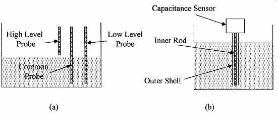
FIG. 6 Methods of measuring liquid levels (a) using conductive probes
for detecting set levels and (b) a capacitive probe for continuous monitoring.
Example 3 A capacitive probe 30-in long has a capacitance of 22 pF in air. When partially immersed in water with a dielectric constant of 80 the capacitance is 1.1 nF.
What is the length of the probe immersed in water?
From Eq. (eqn. 6)
Ultrasonics can be used for single point or continuous level measurement of a liquid or a solid. A single ultrasonic transmitter and receiver can be arranged with a gap as shown in FIG. 7a to give single-point measurement. As soon as liquid fills the gap, ultrasonic waves from the transmitter reach the receiver. A setup for continuous measurement is shown in FIG. 7b. Ultrasonic waves from the transmitter are reflected by the surface of the liquid to the receiver; the time for the waves to reach the receiver is measured. The time delay gives the distance from the transmitter and receiver to the surface of the liquid, from which the liquid level can be calculated knowing the velocity of ultrasonic waves. As there is no contact with the liquid, this method can be used for solids and corrosive and volatile liquids. In a liquid the transmitter and receiver can also be placed on the bottom of the container and the time measured for a signal to be reflected from the surface of the liquid to the receiver to measure the depth of the liquid.
3.2 Indirect level sensing
The most commonly used method of indirectly measuring a liquid level is to measure the hydrostatic pressure at the bottom of the container. The depth can then be extrapolated from the pressure and the specific weight of the liquid can be calculated using Eq. (eqn. 1). The pressure can be measured by any of the methods given in the section on pressure. The dial on the pressure gauge can be calibrated directly in liquid depth. The depth of liquid can also be measured using bubblers, radiation, resistive tapes, and by weight measurements.
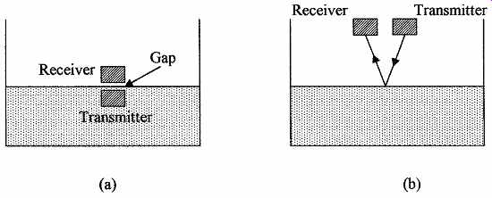
FIG. 7 Use of ultrasonics for (a) single-point liquid level measurement
and (b) continuous liquid level measurements made by timing reflections
from the surface of the liquid.
Example 4 A pressure gauge located at the base of an open tank containing a liquid with a specific weight of 54.5 lb/ft^3 registers 11.7 psi. What is the depth of the fluid in the tank? From Eq. (eqn. 1)
Bubbler devices require a supply of clean air or inert gas. The setup is shown in FIG. 8a. Gas is forced through a tube whose open end is close to the bottom of the tank. The specific weight of the gas is negligible compared to the liquid and can be ignored. The pressure required to force the liquid out of the tube is equal to the pressure at the end of the tube due to the liquid, which is the depth of the liquid multiplied by the specific weight of the liquid. This method can be used with corrosive liquids as the material of the tube can be chosen to be corrosion resistant.
Example 5 How far below the surface of the water is the end of a bubbler tube, if bubbles start to emerge from the end of the tube when the air pressure in the bubbler is 148 kPa? From Eq. (eqn. 1)
Radiation methods are sometimes used in cases where the liquid is corrosive, very hot, or detrimental to installing sensors. For single-point measurement only one transmitter and a detector are required. If several single-point levels are required, a detector will be required for each level measurement as shown in FIG. 8b. The disadvantages of this system are the cost and the need to handle radioactive material.
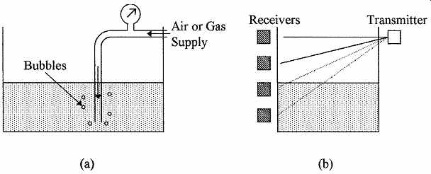
FIG. 8 Liquid level measurements can be made (a) using a bubbler technique
or (b) using a radiation technique.
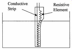
FIG. 9 Demonstrating a resistive tape level sensor.
Resistive tapes can be used to measure liquid levels (see FIG. 9). A resistive element is placed in close proximity to a conductive strip in an easily compressible nonconductive sheath; the pressure of the liquid pushes the resistive element against the conductive strip, shorting out a length of the resistive element proportional to the depth of the liquid. The sensor can be used in liquids or slurries, it is cheap but is not rugged or accurate, it is prone to humidity problems, and measurement accuracy depends on material density.
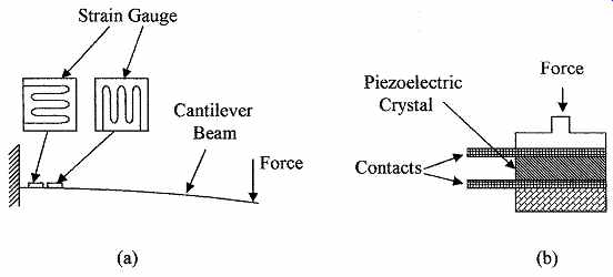
FIG. 10 Force sensors can be used for measuring weight using (a) strain
gauge technique or (b) a piezoelectric technique.
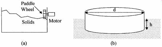
FIG. 11 Shows (a) Paddle wheel technique to measure the level of free
flowing solids and (b) a typical float shape.
Load cells can be used to measure the weight of a tank and its contents. The weight of the container is subtracted from the reading, leaving the weight of the contents of the container. Knowing the cross-sectional area of the tank and the specific weight of the material, the volume and/or depth of the contents can be calculated. This method is well suited for continuous measurement and the material being weighed does not come into contact with the sensor. FIG. 10 shows two elements that can be used in load sensors for measuring force. FIG. 10a shows a cantilever beam used as a force or weight sensor. The beam is rigidly attached at one end and a force is applied to the other end, a strain gauge attached to the beam is used to measure the strain in the beam, a second strain gauge is used for temperature compensation. FIG. 10b shows a piezo electric sensor used to measure force or weight. The sensor gives an output voltage proportional to the force applied.
Example 6 What is the depth of the liquid in a container, if the specific weight of the liquid is 82 lb/ft^3 ; the container weights 45 lb and is 21 in. in diameter? A load cell measures a total weight of 385 lb.
Using Eq. (eqn. 4) and (eqn. 5) we get the following:
Paddle wheels driven by electric motors can be used for sensing the level of solids in the form of power, grains, or granules. When the material reaches and covers the paddle wheel, the torque needed to turn the motor greatly increases.
The torque can be an indication of the depth of the material. Such a set up is shown in FIG. 11a. Some agitation may be required to level the solid particles.
4 Application Considerations
A number of factors affect the choice of sensor for level measurement, such as pressure on the liquid, liquid temperature, turbulence, volatility, corrosiveness, accuracy needed, single-point or continuous measurement, direct or indirect, particulates in a liquid, free flowing solids, and so forth.
Floats are often used to sense fluid levels because they are unaffected by particulates, can be used for slurries, can be used with a wide range of liquid specific weights, and flat floats due to their area are less susceptible to turbulence on the surface of the liquid. FIG. 11b shows a commonly used design for a float which can be attached to a level indicator. The float displaces its own weight of liquid as follows:
(eqn. 10)
where gL = specific weight of the liquid
d = diameter
h = immersion depth of the float
Float weight buoyant force == ?p L dh 2 4
When the float is used to measure one or more feet of liquid depth, any change in h due to large changes in gL will have minimal effect on the measured liquid depth.
Displacers must never be completely submerged when measuring liquid depth and must have a specific weight greater than that of the liquid. Care must also be taken to ensure that the displacer is not corroded by the liquid and the specific weight of the liquid is constant over time. The temperature of the liquid may also have to be monitored to make corrections for density changes. Displacers can be used to measure depths up to about 3 m with an accuracy of ±0.5 cm.
Capacitive device accuracy can be affected by the placement of the device, so the manufacturer's installation instructions must be followed. The dielectric constant of the liquid should also be regularly monitored. Capacitive devices can be used in pressurized containers up to 30 MPa and temperatures up to 1000°C, and measure depths up to 6 m with an accuracy of ±1 percent.
Pressure gauge choice for measuring liquid levels can depend on a number of considerations, which are as follows:
1. The presence of particulates that can block the line to the gauge
2. Damage caused by excessive temperatures in the liquid
3. Damage due to peak pressure surges
4. Corrosion of the gauge by the liquid
5. Differential pressure gauges are needed if the liquid is under pressure
6. Distance between the tank and the gauge
7. Use of manual valves for gauge repair
Differential pressure gauges can be used in pressurized containers up to 30 MPa and temperatures up to 600°C to give accuracies of ±1 percent, the liquid depth depends on its density and the pressure gauge used.
Bubbler devices require certain precautions when being used. To ensure a continuous air or gas supply, the gas used must not react with the liquid. It may be necessary to install a one way valve to prevent the liquid being sucked back into the gas supply lines if the gas pressure is lost. The bubbler tube must be chosen so that it is not corroded by the liquid. Bubbler devices are typically used at atmospheric pressure, accuracies of about 2 percent can be obtained, depth depends on gas pressure available, and so forth.
Ultrasonic devices can be used with pressurized containers up to 2 MPa and 100°C temperature range for depths of up to 30 m with accuracies of about 2 percent.
Radiation devices are used for point measurement of hazardous materials.
Due to the hazardous nature of the material, personnel should be trained in its use, transportation, storage, identification, and disposal.
Other considerations are that liquid level measurements can be effected by turbulence, readings may have to be averaged, and/or baffles used to reduce the turbulence. Frothing in the liquid can also be a source of error particularly with resistive or capacitive probes.
Summary
This Section introduced the concepts of level measurement. The instruments used for direct and indirect measurement have been described and the application of level measuring instruments considered.
The key points covered in this Section are as follows:
1. The formulas used by instruments for the measurement of liquid levels and free flowing solids with examples
2. The various types of instruments used to give direct measurement of liquid levels and the methods used to indirectly measure liquid levels
3. The difference between continuous and single-point level measurements in a liquid
4. Application considerations when selecting an instrument for measuring liquid and free flowing solid levels
Problems
1 What is the specific weight of a liquid, if the pressure is 4.7 psi at a depth of 17 ft?
2 What is the depth of a liquid, if the pressure is 127 kPa and the liquid density is 1.2 g/cm3?
3 What is the displaced volume in cubic meters if the buoyancy on an object is 15 lb and the density of the liquid is 785 kg/m3?
4 What is the liquid density in gram per cubic centimeter, if the buoyancy is 833 N on a 135 cm^3 submerged object?
5 The weight of a body in air is17 lb and submerged in water is 3 lb. What is the volume and specific weight of the body?
6 A material has a density of 1263 kg/m3. A block of the material weighs 72 kg when submerged in water. What is its volume and weight in air?
7 A container of 4.5-ft diameter is full of liquid. If the liquid has a specific weight of 63 lb/ft^3 , what is the depth of the liquid if the weight of the container and liquid is 533 lb? Assume the container weighs 52 lb.
8 The weight of liquid in a round container is 1578 kg, the depth of the liquid is 3.2 m. If the density of the liquid is 0.83 g/cm^3 , what is the diameter of the container?
9 A capacitive sensor is 3 ft^3 in high and has a capacitance of 25 pF in air and 283 pF when immersed in a liquid to a depth of 2 ft 7 in. What is the dielectric constant of the liquid?
10 A capacitive sensor 2.4 m in height has a capacitance of 75 pF in air if the sensor is placed in a liquid with a dielectric constant of 65 to a depth of 1.7 m. What will be the capacitive reading of the sensor?
11 A pressure gauge at the bottom of a tank reads 32 kPa. If the tank has 3.2 m diameter, what is the weight of liquid in the container?
12 What pounds per square inch is required by a bubbler system to produce bubbles at a depth of 4 ft 7 in water?
13 A bubbler system requires a pressure of 28 kPa to produce bubbles in a liquid with a density of 560 kg/m^3. What is the depth of the outlet of the bubbler in the liquid?
14 A displacer with a diameter of 4.7 cm is used to measure changes in the level of a liquid with a density of 470 kg/m^3. What is the change in force on the sensor if the liquid level changes 13.2 cm?
15 A displacer is used to measure changes in liquid level. The liquid has a density of 33 lb/ft^3. What is the diameter of the dispenser if a change in liquid level of 45 in produces a change in force on the sensor of 3.2 lb?
16 A bubbler system requires a pressure of 47 kPa to produce bubbles at a depth of 200 in. What is the density of the liquid in pounds per cubic foot?
17 A capacitive sensing probe 2.7 m high has a capacitance of 157 pF in air and 7.4 nF when partially immersed in a liquid with a dielectric constant of 79. How much of the probe is immersed in the liquid?
18 A force sensor is immersed in a liquid with a density of 61 lb/ft 3 to a depth of 42 in and then placed in a second liquid with a density of 732 N/m^3. What is the change in force on the sensor if the diameter of the sensor is 8 cm and the change in depth is 5.9 cm?
19 An ultrasonic transmitter and receiver are placed 10.5 ft above the surface of a liquid. How long will the sound waves take to travel from the transmitter to the receiver? Assume the velocity of sound waves is 340 m/s 6.20 If the liquid in Prob. 19 is lowered to 6.7 ft, what is the increase in time for the sound waves to go from the transmitter to the receiver?
Related Articles -- Top of Page -- Home