AMAZON multi-meters discounts AMAZON oscilloscope discounts
1. Piezoresistive Pressure Sensing
Pressure sensors convert input pressures to electrical outputs to measure pressure, force and airflow. These measurements are used to control everything from the water level in your washing machine to the gases emitted by your car's exhaust system.
Pressure sensors are used in medical equipment to monitor blood pressure, regulate intravenous infusions, and to detect such things as changes in cranial pressure, hearing problems and glaucoma. People in the manufacturing and process industries rely on pressure sensors to control their machinery and processes. They are essential to the operation of HVAC systems, forklifts, and earth-moving equipment. They measure altitude and turbidity on aircraft and are an important feature of the flight data recorders required on all commercial flights.
Wherever pressure, force or airflow needs to be precisely controlled, there is a potential pressure sensing application. Today's pressure sensors provide a high degree of repeatability, low hysteresis, and long-term stability in applications with input pressures ranging from less than one pound per square inch gauge (psig) to thousands of psig.
Fundamentals of Pressure Sensing Technology
Most pressure, force and airflow sensors are fabricated using silicon-processing techniques common in the semiconductor industry. Therefore, much of the same terminology used in the semiconductor industry also applies to pressure sensor technology. Piezoresistive ion implanted semiconductor technology dominates the component market for pressure sensors for many good reasons. Other approaches, including variable reluctance, variable capacitance, fiber optic, and piezoelectric, are available for niche applications; however, those technologies are not covered in this SECTION.
Piezoresistive pressure sensors (strain gage sensors) are often referred to as IC (integrated circuit) sensors, solid-state sensors, monolithic sensors (formed from single-crystal silicon) or just silicon sensors. They are processed in wafer form, where each wafer will contain a few hundred to a few thousand sensor die, depending on the size of the sensor die. A typical sensor chip measures 80 × 80 mils or 2 mm × 2 mm.
Piezoresistive (silicon) pressure sensors contain a sensing element made up of a silicon chip with a thin, circular silicon diaphragm and four piezoresistors. These nearly identical solid-state resistors are buried in the surface of the silicon.
The piezoresistance of a semiconductor refers to the change in resistance caused by strain when pressure or force is applied to the diaphragm. Pressure causes the diaphragm to flex, inducing a stress on the diaphragm and also on the buried resistors.
The resistor values change depending on the amount of pressure applied to the diaphragm. Therefore, a change in pressure (mechanical input) is converted to a change in resistance (electrical output). The sensing element converts or transduces the energy from one form to another, hence the term "pressure transducer." Pressure sensors are produced first by ion implanting the four piezoresistors into the silicon. Ion implantation is used increasingly to provide improved performance over sensors produced by diffusion.
After the four piezoresistors are formed, the diaphragm is created by chemically etching a controlled shape in the silicon from its backside (on the surface opposite the piezoresistors). The unetched portion of the silicon slice provides a rigid boundary constraint for the diaphragm and a surface for mounting it to some other member.
The thickness of the diaphragm determines the pressure range (sensitivity) of the sensor. However, this relationship is not a linear function. For example, doubling the thickness of the diaphragm decreases the sensitivity by a factor of four. Typical diaphragm thicknesses are 5 to 200 microns (pretty thin stuff), depending on their pressure range. Overpressure is a term used to specify the maximum pressure that may be applied to a sensor's sensing element without causing a permanent change in its output characteristics.
The high sensitivity or gage factor of silicon strain gages is approximately 100 times that of metal strain gages. By implanting the piezoresistors into a homogenous single crystalline silicon medium, they are integrated into the silicon force-sensing element. Typically, other types of strain gages are bonded to force sensing members of dissimilar material, resulting in thermoelastic strain and complex fabrication processes. Most discrete strain gages are inherently unstable due to bond degradation, temperature sensitivity, and hysteresis caused by thermo elastic strain. Silicon diaphragm pressure sensors are extremely reliable because silicon is an ideal material for receiving the applied force, and the implanted gages are not subject to bonding problems.
As a perfect crystal, silicon does not become permanently stretched but returns to its original shape. Silicon wafers are better than metal for pressure sensing diaphragms because silicon offers extreme elasticity within its operating range.
Silicon diaphragms normally fail only by rupturing, usually due to extreme overpressure. Micromachining and laser trimming help manufacturers produce reliable sensors capable of extreme accuracy.
The sensor's resistors can be connected in either a half-bridge or a full "Wheatstone bridge" arrangement, whereby two resistors increase with positive pressure while the other two decrease in resistance. When pres sure is applied to the device as shown in FIG. 1.1, the resistors in the arms of the bridge change by an amount, fir. The alignment of the resistor on the silicon determines if the resistor will increase or decrease with applied pressure.
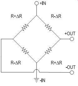
FIG. 1.1
The resulting differential output voltage VO, is easily shown to be VO = VBx AR/R. Since the change in resistance is directly proportional to pressure, VO can be written as:
VO = (SxPxVB) ± VOS
... where:
VO is the output voltage in mV
S is the sensitivity in mV/V per psi.
P is the pressure in psi.
VB is the bridge voltage in volts.
VOS is the offset error (the differential output voltage when the applied pressure is zero).
The differential output of a "raw" pressure sensor is, however, not precise in terms of calibration and temperature effects. It is partially because of this that sensor manufacturers offer a variety of levels of signal-conditioned sensors from their basic raw state, up through fully calibrated and compensated transmitters with amplified outputs and application-specific integrated circuits (ASIC).
Types of Pressure Measurements
Pressure sensors are categorized, in part, by the type of pressure they measure. Most sensors are offered in a series of products with different listings designed to measure different types of pressure: gauge, differential, absolute, or vacuum gauge.
Most people are accustomed to dealing in gauge pressure--that is, pressure relative to the normal atmospheric pressure that surrounds us. As such, absolute pressure and absolute pressure sensors, which measure pressure relative to a perfect vacuum, can be confusing. Since the zero absolute pressure of a perfect vacuum is impractical to achieve, absolute pressure is much more difficult to measure. It is easier to understand absolute pressure once you have a clear understanding of the more familiar differential and gauge pressures.
Differential pressure is the difference in pressure between two pressure sources--for instance, measuring two sources of pressure to determine the status of a filter. This type of pressure measurement is usually expressed in pounds per square inch differential (psid).
Differential pressure sensors are designed to simultaneously accept two independent pressure sources, so they have two pressure ports. The output is proportional to the pressure difference between the two sources, so we can use this output to determine if the filter needs to be cleaned or replaced. Bidirectional differential pressure sensors are differential pressure sensors that allow the greater input pressure to be applied to either pressure port.
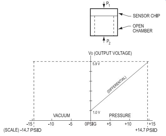
FIG. 1.2: A signal-conditioned, differential pressure sensor output
is shown. One-volt output occurs when pressures are equal on both ports.
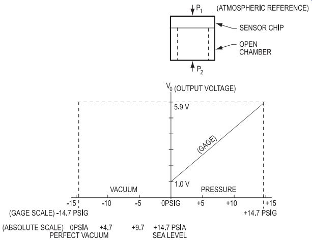
FIG. 1.3: A high-level gauge pressure sensor output is shown. One-volt
output represents ambient pressure.
In the differential pressure sensor shown in FIG. 1.2, measurands (the physical parameters being quantified by the measurements) are applied to both ports.
When one of these two pressure sources is ambient pressure, this is then called gauge pressure. Therefore, gauge pressure is a form of differential pressure measurement in which atmospheric pressure is used as the reference. Measurement of auto tire pressure, where a pressure above atmospheric pressure is needed to maintain tire performance characteristics, is an example. With a gauge device, as shown in FIG. 1.3, the P1 port is vented to atmospheric pressure, and the measurand is applied to the P2 port.
Absolute pressure is measured with respect to a vacuum reference. Absolute pres sure sensors are most commonly used to measure changes in barometric pressure or as altimeters. These applications require reference to a fixed pressure, as they cannot simply be referenced to the surrounding ambient pressure.
Absolute pressure sensors must measure input pressure in relation to zero pressure (a total vacuum on one side of the diaphragm). For example, 10 pounds per square inch absolute (psia) would be 10 psi above a perfect vacuum. This is roughly 4.7 psi below the standard atmospheric pressure at sea level of 14.7 psia. Zero psia is then the pres sure of a perfect vacuum.
In the absolute pressure sensor shown in FIG. 1.4, the P2 port is sealed with a vacuum representing a fixed reference. The difference in pressure between the vacuum reference and the measurand applied at the P1 port causes the deflection of the diaphragm, producing the output voltage change.
Note: For illustrative purposes, pounds per square inch (psi) is used as the unit of pressure measure. This unit can obviously be converted to other common pressure units such as in Hg, kPa, bar, and so forth.
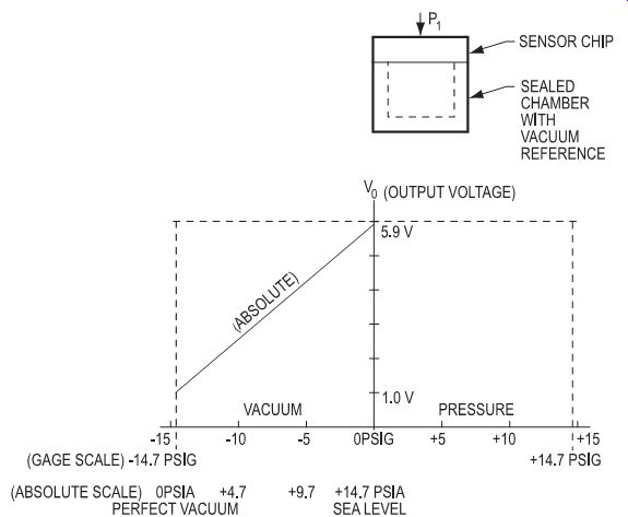
FIG. 1.4: A signal-conditioned, absolute pressure sensor output is
shown. One-volt output represents a perfect vacuum.
Absolute pressure sensors can be made by hermetically sealing a vacuum reference chamber to one side of the sensing element. (See FIG. 1.5.) Pressures to be measured are then measured relative to this vacuum reference. The actual "vacuum," which is sealed into the sensor, is approximately 0.0005 psia (25 millitorr). If gas becomes trapped in the reference chamber, it will exert pressure during expansion and contraction with temperature in accordance with Boyle's law, so this near absolute vacuum is used as a reference to eliminate any potential thermal errors. One of the advantages of the integrated circuits of piezoresistive sensors is the small volume of trapped vacuum reference, which, in conjunction with a reliable silicon-to-silicon hermetic seal, makes these devices time and temperature stable.
Finally, vacuum gauge pressure is a form of pressure measurement in which vacuum pressures are sensed with reference to ambient pressure. FIG. 1.6 shows an out put from a vacuum gauge sensor.
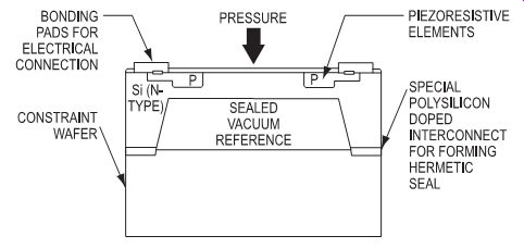
FIG. 1.5: An absolute pressure sensor with a hermetically sealed
vacuum reference chamber on one side of the sensing element.
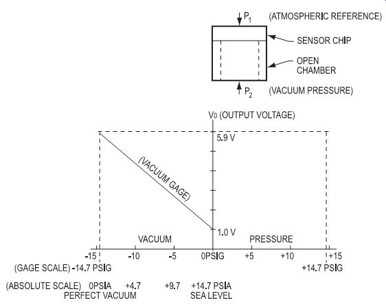
FIG. 1.6: A high-level vacuum gauge sensor output is shown.
One-volt output represents ambient pressure.
Selecting and Specifying Pressure Sensors
With the type or types of pressure you need to measure in mind, you can begin to narrow your search for the right sensors by considering the performance parameters that are important in your specific application.
Sensor manufacturers want to insure the sensors you purchase are compatible with your application, and most suppliers offer some type of application data sheet to help you gather the information needed to specify the right sensors for your application.
For example, point your browser here for a form listing the most relevant specifications for selecting pressure sensors, including pressure, accuracy, electrical packaging and environmental requirements.
What pressure will the transducer measure?
Your first consideration is the maximum pressure of your system. In general, you want to use a transducer that has a maximum pressure range of at least 1.5 times the maximum pressure expected in your system. This extra capacity is advised because many systems, especially hydraulic and process control systems, have pressure spikes or continuous pulsations. The spikes can be five to ten times over the "maximum" pressure. These high-pressure, short-duration spikes can destroy a pressure transducer.
Continuous high-pressure pulsations, near or slightly above a transducer's rated maxi mum, can also limit the life of the transducer. If pulsation frequencies approach the natural (resonance) frequency of the transducer, even low-amplitude pulsations can cause resonance excitation and damage the transducer. However, specifying a higher range transducer is not always a solution because you will sacrifice resolution. You can use a snubber to reduce the spikes, but this is also a trade-off in that it slows the response time of the transducer.
In a sensor's specifications, Span or full-scale output is the algebraic difference between the upper and lower limits of the sensor's pressure range (the difference between the output curve endpoints). Normally these endpoints are null and full scale.
Null offset (zero measurand output or ZMO) is the electrical output that occurs when the pressures or forces on both sides of the sensor's diaphragm are equal. "Null" refers to the equal pressure and "null offset" to the output you get when the pressure is at null.
Most manufacturers can tell you how many cycles their products are designed to with stand without loss of performance. For example, Honeywell designs to more than 200 million full-pressure cycles. Consider the system pressure carefully when choosing a transducer. You will be trading off system accuracy versus life of the transducer.
What is the pressure medium?
Another key factor you must consider when selecting a transducer is the medium it will measure. Is it a viscous liquid or a slurry that could plug a pressure port? Is it a solvent or corrosive that could attack the transducer's materials in contact with it, or is it clean, dry air?
These questions will determine whether you need a flush diaphragm device and what materials can be in contact with the medium. Some models have flush diaphragms and others have pressure ports. You can specify stainless steel diaphragms when there is contact with the medium to reduce problems caused by corrosive media. (See FIG. 1.7.)
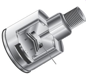
FIG. 1.7: For sensing in harsh or wet environments, you can specify
a stainless steel pressure cavity to protect performance.
How accurate does the transducer need to be?
Accuracy is a general term used by many transducer manufacturers to describe the measurement error or uncertainty in the transducer's output. Sources of these errors may include nonlinearity, hysteresis, non-repeatability, temperature, zero balance, calibration and humidity effects. Most manufacturers specify "accuracy" as the combined effects of nonlinearity, non-repeatability, and hysteresis. Other errors may be specified separately.
Linearity error is the deviation of the sensor output curve from a specified straight line over a desired pressure range (the degree to which the output of a linear device deviates from ideal performance). It is usually expressed as a percent of full-scale out put. One method of computing linearity error is least squares, which mathematically provides a best fit straight line (B.F.S.L.) to the data points (See FIG. 1.8.) When selecting a pressure transducer, the user must be careful to define the method used to calculate linearity error.
Another method of defining linearity is terminal base linearity (T.B.L.) or end point linearity. (See FIG. 1.9.) T.B.L. is determined by drawing a straight line (L1) between the end data points on the output curve. Next draw a perpendicular line from line L1 to a data point on the output curve. The data point is chosen to achieve the maximum length of the perpendicular line. The length of the perpendicular line represents terminal base linearity error. T.B.L. is approximately twice the magnitude of B.F.S.L.
Repeatability error is the deviation in output readings for successive applications of any given input pressure with other conditions remaining constant. (FIG. 1.10). Hysteresis error is usually expressed as a combination of mechanical hysteresis and temperature hysteresis. FIG. 1.11 expresses hysteresis as a combination of the two effects.
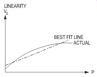
FIG. 1.8: Best fit straight line linearity.
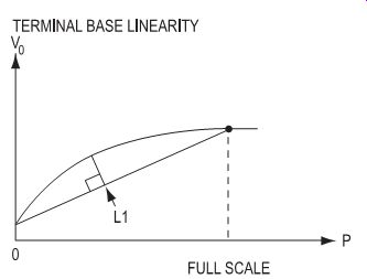
FIG. 1.9: Terminal base linearity.
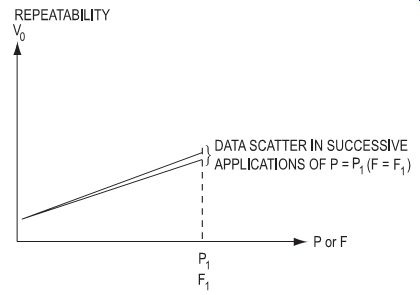
FIG. 1.10: Repeatability error.
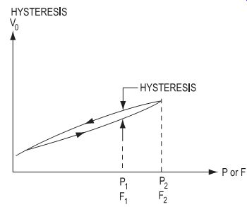
FIG. 1.11: Hysteresis.
Mechanical hysteresis is the output deviation at a certain input pressure when that input is approached first with increasing pressure and then with decreasing pressure.
For many transducers, "accuracy" errors are less than those due to zero balance or temperature. Higher accuracy transducers generally cost more. Does your system truly need this higher accuracy? Using a high-accuracy transducer with a low-resolution measurement instrument creates an ineffective solution.
What temperatures will the transducer see? Pressure transducers, like all physical measurement systems, are subject to error or failure from extreme temperatures. There are usually two temperature ranges specified for a transducer. They are the operating and compensated ranges. The compensated range is a subset of the operating range.
The operating temperature range is that temperature range over which the transducer can be exposed while energized and not suffer damage. However, it will not meet its published performance specifications (temperature coefficients) when subjected to temperatures outside the compensated temperature range.
The compensated temperature range is typically a narrower range within the operating range. Within this band, the transducer is guaranteed to meet its published specifications. Changes in temperature affect the output of the transducer in two ways. They may cause the zero output to change and may also affect the full-scale output. The transducer performance specification should list these temperature errors as:
¦ ± x% of full scale/°C,
¦ ± x% of reading/°C,
¦ ± x% of full scale over the entire compensated temperature range, or
¦ ± x% of reading for the entire compensated temperature range.
Not having these figures available will cause you uncertainty when using a transducer.
Is the change in transducer output due to a change in pressure or a change in temperature? Most manufacturers specify the operating and compensated ranges and the temperature coefficients of zero and Span for each product. The temperature effects on a transducer are often the most complicated part of understanding how to use a transducer.
Null temperature shift (thermal zero shift) Null temperature shift is the change in output at null pressure resulting from a change in temperature. Null temperature shift is not a predictable error because it can shift up or down from unit to unit. A change in temperature causes the entire output curve to shift up or down along the voltage axis. (See FIG. 1.12.)
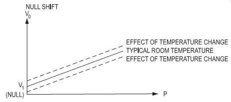
FIG. 1.12: Null shift error.
Sensitivity temperature shift is the change in sensitivity due to change in temperature.
Change in temperature causes a change in the slope of the sensor output curve. (See FIG. 1.13.) The more generic error sensitivity shift refers to a change in sensitivity from any environmental change.
Temperature hysteresis is the output deviation at a certain input, before and after a temperature cycle.
In some applications, some of the manufacturer's published specifications can be reduced or eliminated. For example, if a sensor is used over half the specified temperature range, then you can reduce the specified temperature error by half.
What output signal should I use?
Nearly all transducers are available with a choice of millivolt, amplified voltage, milli ampere, or frequency output. The output you select will depend on the distance between the transducer and your system's controller or display, the presence of "noise" or other electrical interference, whether amplification is necessary, and where it is best to place the amplifier. For many OEM products with a short distance between the transducer and the controller, millivolt output is usually adequate and less costly.
If you need to amplify a transducer's output, it may be easier to use a different transducer with a built-in amplifier. For long cable runs, or areas with high electrical noise, a milliampere or frequency output is desirable. For environments with very high levels of radio frequency interference or electromagnetic interference (EEI or EMI), you will need to consider special shielding and filtering in addition to milliampere or frequency outputs.
What is excitation voltage?
The type of output desired might determine the excitation voltage you need. Many amplified transducers have built-in voltage regulators and will operate over a wide range of voltages from an unregulated power source. Some transducers are ratiometric and require a regulated excitation. Ratiometricity implies the sensor output is proportional to the supply voltage with other conditions remaining constant. Ratiometricity error is the change in this proportion and is usually expressed as a percent of Span.
The power available may dictate whether you use a regulated or unregulated transducer. Consider the trade-offs between the available excitation and system cost. Many transducer or strain gage amplifiers will provide either a regulated voltage or a regulated current excitation.
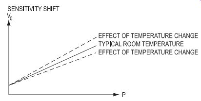
FIG. 1.13: Sensitivity shift error.
Do I need the transducer to be interchangeable?
Is it important that the transducers are interchangeable from system to system, or will you calibrate each unit as part of the system? This is important, especially for an OEM. Once you have shipped your product to your customer, the cost of field calibration can be very high. If the transducers are truly interchangeable, you should be able to replace a transducer in the field and expect the system to stay within specification.
How stable does the transducer need to be over time? Most transducers will "drift" somewhat over time. It is important to discuss long-term stability with the transducer vendor. This up-front work can pay off in fewer field problems in the future.
How will I connect the transducer to my electrical system? Will a short cable on the transducer be adequate? Or, in the case of long cable runs, should I have a connector on the transducer? Most pressure transducers can be supplied with cable or optional connectors.
How rugged does the transducer need to be?
One factor that is often overlooked, much to the chagrin of the user, is the ruggedness of the transducer, especially its housing. It is crucial to consider the transducer's prospective operating environment. Is it high in moisture or humidity? How will the transducer be installed? Will there be high levels of shock or vibration? All of these questions should be considered when selecting a housing style.
Because pressure sensors are used in such a wide variety of applications, they are available as light-duty units in cost-effective plastic housings, up through hermetically sealed devices encased in stainless steel housings for extreme or hazardous environments, areas with corrosive chemicals, and applications with sterility concerns, such as food processing or medical equipment manufacturing.
Here's a look at a number of applications where the environment in which the sensor needs to work is important to sensor selection.
1. Autoclaves and sterilizers used in medical, food and process industries
Sterilizers are used primarily to reduce biohazards by disinfecting instruments or treating biohazard waste before disposal. They can use steam, gas, electricity and UV rays to kill bacteria, but pressure sensors are only used in steam or gas sterilizers. Autoclaves have many uses, including curing and bonding, treating wood and growing chemical crystals. They work exclusively with pressurized steam chambers and may be as small as a microwave or as large as a room.
Functions of the sensor: Pressure measurements on the refrigerant are typically made at the compressor inlet (low-pressure gas) and outlet (high pressure gas), and at other locations in the cycle. The pressures involved range from approximately 100 to 500 psi. Measurements may also be made on the lubricating oil for the compressor or media to be cooled (gas or liquid). Temperatures may range from -100°C to +250°C.
Recommended environmental specifications:
¦ All-wetted design, sealed for dust, moisture and RFI/EMI
¦ Stainless steel housing
¦ Temperature range wider than expected temperatures
¦ Amplified output compatible with relevant controllers
3. Off-road vehicles used in agricultural and construction, and material handling equipment for manufacturing, distribution or disposal applications
Off-road vehicles have the ability to cross terrain while hauling, lifting, towing or moving solid materials.
Process: Most dump trucks, aerial lift trucks, loaders, excavators and material handling equipment, such as hoists, lifts and fork lifts, use hydraulics to move material.
Sensor functions: Off-road vehicle OEMs use pressure transducers to measure the oil pressure in their engines to maximize efficiency and ensure performance. Typical pressure ranges are 150 to 200 psi. Due to the proximity of the sensor to the engine, it must be able to withstand high-end temperature ranges of 1250 to 1400°C.
Pressure sensors are also used to measure hydraulic pressure, which can be measured both at its source as the hydraulic charge pressure and in the system.
Source pressures typically range from 700 to 800 psi, and system pressure ranges can vary from 4,000 to 9,000 psi. The hydraulic pressure provides the vehicle or equipment operator with feedback and balances the power delivered against the load to be lifted.
Recommended environmental specifications:
¦ Stainless steel package designed to withstand extreme environments, including protection from dust, humidity, bumps, shocks, and wash-downs
¦ EMC protection, overvoltage and reverse voltage protection
¦ -40 to +150°C temp (generally)
4. Industrial air compressors used to supply air for operation of pneumatic controls, actuators or power tools.
The application determines the type and size of industrial air compressors, which range in size from 2 to 10,000 HP and may be fixed or portable. The most common pressure is 125 psi with the amount of air volume ranging from 1 to 15,000 CFM.
Process:
a. Reciprocating compressors take air into a confined space and elevate it to a higher pressure using a piston within a cylinder as the compressing and displacing element.
b. Rotary compressors use two rotors to take in and compress air within a casing.
c. Centrifugal compressors depend on the transfer of energy from a rotating impeller to the air. The rotor changes the momentum and pressure of the air, slowing it down.
Sensor functions: A pressure transducer detects pressure drops across separators used to remove dirt, water and oil from the air. Removal of such contaminants is critical to the efficiency and life of the compressor and neglect can result in costly downtime. Manufacturers typically require filter changes when the pressure drop reaches 10 psi, which is approximately 6 to 12 months of operation. Total pressure drop is 14 psi (new filter elements) and 35 psi (dirty). The amount of energy consumed is also a major consideration.
Recommended environmental specifications:
¦ Stainless steel housing
¦ Compensated temperature range with error band of less than 1% FS over the full temperature range
¦ Shock and vibration protection
¦ Electrical isolation of media from the electronics
¦ Application-specific integrated circuit with amplified output
¦ Small size
Applicable Standards
ANSI (American National Standards Institute): ansi.org
FDA (Food and Drug Administration): http://www.fda.gov Products for food and beverage applications may require FDA and ANSI/NSF agency approvals based on whether the product is exposed to the application medium. The sensor itself would not require FDA approval.
FM (Factory Mutual):
factorymutual.com
IEC (International Electrotechnical Commission):
iec.ch
IEEE ( Institute of Electrical and Electronics Engineers):
ieee.org
ISA (Society for Instrumentation, Systems and Automation):
isa.org
NEMA (National Electrical Manufacturers Association):
nema.org
UL (Underwriter's Laboratories):
ul.com
Interfacing and Design Information
As you design your application, it's important to understand that pressure sensors are not "ideal" devices. Laser trimming on high-level amplified sensors generally reduces null and full-scale errors to approximately one to two percent of Span but does not completely eliminate them. Additional corrective circuitry is sometimes necessary for applications with extremely tight tolerances.
FIG. 1.14 illustrates the "ideal" pressure sensor. Output drift with time, trimming tolerances, and changes in ambient temperature all contribute to a constant offset error (common-mode error), designated by fivo. Changes in ambient temperature also add another deviation, known as sensitivity shift, which changes the slope of the pres sure versus voltage curve.
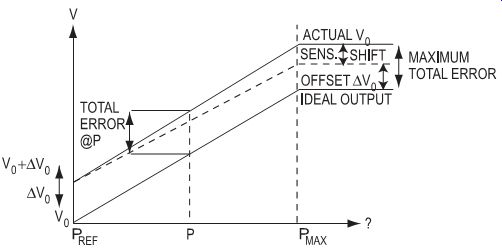
FIG. 1.14: Sensor errors.
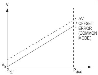
FIG. 1.15: Common-mode errors.
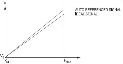
FIG. 1.16: Auto-referenced signal.
Methods known as auto-referencing techniques provide a powerful tool to compensate for these errors. System design engineers find these methods attractive since implementation costs are minor in comparison with ultra-stable pressure sensors.
Also, device accuracy is substantially increased. Either analog or digital auto-referencing is possible. The digital method is the most cost-effective and easiest to use.
When the accuracy limits of the auto-reference circuit replace errors, the errors can be reduced by as much as 250 times, leaving only the sensitivity shift (normal-mode)
error. This is a significant improvement for the added cost involved. In any application where maximizing sensor accuracy is of value, consider an auto-referencing circuit.
Common-mode auto-referencing replaces common-mode error sources. Common mode errors are present at some reference pressure and contribute the constant offset voltage shown in FIG. 1.14. These errors are generally larger than the sensitivity shift, especially at pressures close to the reference pressure. Therefore, they allow the greatest accuracy improvement when auto-referenced.
Common-mode errors are easily corrected.
Sample the output voltage at reference pres sure and compare it to the desired reference voltage. Generate an error correction voltage and subtract it from the output signal at any "measure" pressure. (See FIG. 1.15.) Common-mode auto-referencing is expressed by the formula:
Vcorr = Vout - fivo.
Vout is any measured output signal; fivo is the common-mode error, and Vcorr is the corrected output signal. Note that no slope correction is provided for sensitivity shift error, and the actual output signal will appear as shown in FIG. 1.16.
The basic functions required to implement common-mode auto-referencing are shown in the block diagram of FIG. 1.17. They include analog switches, a sample-and-hold, summers, and synchronizing logic for switching between the read and reference cycles on the input and output sides of the pressure sensor. To maintain optimum system accuracy, auto-referencing should be used as often as possible in order to eliminate errors due to power supply fluctuations and output drift with time.
To assure that the pressure measurements will be the most accurate, they should immediately follow the auto-reference command.
Although common-mode auto-referencing is almost a universal technique, there are situations where it would be of little value: systems with short measurement cycles where the reference point is read or manually adjusted before cycle startup, or where the sensor is AC coupled and the DC response is ignored.
Certain types of measurement cycles are inherently suited to auto-zeroing (reference pressure is actually zero). Ideally, there is a series of short cycles that can have a quick referencing inserted prior to each cycle. A short measurement cycle preceded by a reference point, followed by a lengthy period of no activity, is also well suited.
Many applications are in one of these categories. Many that are not can be converted to the short repeated cycle format with a little design creativity.
Examples of "ideal" auto-zeroing applications are: weighing scale; toilet tanks; washing machines; and pressure reservoirs such as tire pressure, oil pressure, and LP gas tank pressure. The reference condition is applied before the measurement. Other categories are flow measurement and control applications, such as electronic fuel injection systems, sphygmomanometers, and forced air heating systems. Flow rate is zero at some point, usually at system power-up. If an auto-zeroing technique is used, the null-offset and null-shift errors can be eliminated.
The key to an auto-reference circuit is applying the trigger signal to command the reference to take place at the appropriate time. This is called command auto-referencing.
There are three levels of sophistication:
1. The simplest auto-referencing method is the manual command. A momentary contact switch initiates the auto-zeroing sequence. This is the most restrictive method, as it requires the user to be present while the system is running in order to periodically reference the sensor. However, it could be done as part of a routine calibration procedure.
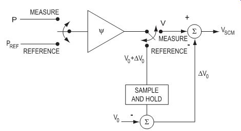
FIG. 1.17: Basic common-mode auto-referencing.
2. With semi-automatic command, the user initiates the action. After it is triggered, the system sequences through multiple functions controlled by timers or shift registers. This could include solenoid actuation to switch from measurement to reference pressure, followed by the auto-reference function, then a return to the measurement mode. FIG. 1.17 illustrates a basic semi-automatic circuit.
3. Using automatic command, the system steps through multiple functions similar to the semi-automatic command. However, on returning to the measurement mode, additional timing circuitry triggers and, after a set measurement time, the sequence is restarted. Depending upon the degree of complexity desired, a small microprocessor-based system and its related soft ware could consolidate the auto-reference circuitry, timing and control logic all into one unit.
Auto-referencing requires an established system reference point. Batch processing and continuous processing are the two main categories of measurement cycle. In a batch process, a reference condition exists at some time, usually at system power-up.
For example, a toilet tank has a high water level prior to flushing, corresponding to some reference pressure. When the flushing cycle is complete, the tank is filled to the previous level. The obvious point for auto-referencing is just prior to flushing when the water is at a known level.
In a continuous process, there is no easily accessed reference condition. For example, the volume of fluid in a water tower is being monitored. This is a function of the depth of the water and can be sensed with a pressure sensor. Unlike the toilet, without actually taking a pressure measurement, there is no point in time at which the depth will be known. The sensor/auto-reference/enable system can be used for a simple case when a known reference exists periodically. Also, a reference condition actuator such as a solenoid valve can be used. It can switch the sensor input from the measured pressure to some other reference pressure.
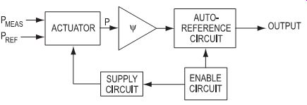
FIG. 1.18: Auto-reference with reference condition actuators.

FIG. 1.19: Timer-actuated circuit, single-port sensor.
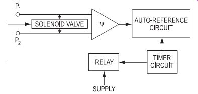
FIG. 1.20: Timer-activated circuit, dual-port sensor
The solenoid can be activated by the user, by some condition such as power-up, or by a timer activated circuit. (See FIG. 1.18.)
The valve must be activated long enough for the pressure to have a chance to stabilize so a valid reading may be taken.
For instance, consider the water tower.
A gauge pressure sensor near the bottom senses the water depth. A vent tube to the surface serves as a pressure reference.
A three-way solenoid valve is the actuator, connecting the water and the vent to the sensor input port. A timer circuit is the enabler. (See FIG. 1.19.) Next, suppose the water exits through a single pipe of constant diameter. The velocity can be measured with a differential pressure sensor. A two-way solenoid connected between the two inlet ports serves as the reference actuator as shown in FIG. 1.20.
Latest and Future Developments
Many of the latest developments associated with pressure sensing involve sensors that provide more than pressure measurements. As more and more control systems become CAN based networks and the systems themselves get "smarter," sensor manufacturers are seizing the opportunity to provide more "information" as opposed to simple output signals.
CAN technology has led to smart sensors that offer a variety of self- and process-related diagnostic functions. They are showing up in "intelligent" appliances, on plant floors, and on-board aircraft and vehicles.
Another trend involves the bundling of different types of sensing elements within the confines of a single chip. Honeywell used this approach when it used a mass airflow sensor to create a microsensor that simultaneously measures ambient temperature, pressure, thermal conductivity and the specific heat of a fluid. Such technology can be applied in chemical plants, chemical storage facilities and on automobiles where, for instance, it enables the engine to adjust itself to changes in fuel properties each time the fuel tank is refilled, resulting in improved gas mileage and cleaner exhaust.
This same approach is being used to develop a high-sensitivity, high-temperature Silicon-On-Insulator (SOI) piezoresistive technology that provides pressure sensing, temperature sensing, and feedback and bias resistor networks all integrated on a single miniature 90-mil-square chip. This technology was designed for applications with both high temperature and high pressure. Its high gage factor is very important in applications where a large "signal-to-noise" ratio is essential to achieving high ac-curacy performance, particularly over wide temperature ranges such as that required by the turbine engine and down hole oil industries. Sample test results show that the sensor design has successfully eliminated and/or minimized mechanical and thermal hysteresis error sources to levels that challenge the measurement capability of present state-of-the-art instrumentation.
References and Resources
PDFs:
1. "Piezoresistive Technology and Pressure Measurement Types," Honeywell, Inc.
2. "Pressure Sensors Conversion Factors and Chart," Honeywell, Inc.
3. "Pressure Sensors Plumbing and Mounting Considerations," Honeywell, Inc.
4. "Pressure or Force Sensor Switch Circuits," Honeywell, Inc.
5. "Protecting Pressure Sensor Diaphragm From Rupture Due To Water Hammer," Honeywell, Inc.
--------
2. Piezoelectric Pressure Sensors
The brothers Pierre and Jacques Curie discovered the piezoelectric effect in 1880. They found that some crystalline materials were generating an electrical polarization when subjected to a mechanical load along some crystal directions. Among the materials they investigated were quartz and tourmaline, two crystals which are today still often used in piezoelectric sensors. The first piezoelectric pressure sensor was reported around 1920, but commercial sensors were not available until the 1950s, when electrometer tubes of sufficient quality became available. Today, piezoelectric pressure sensors are widely used in laboratories and in production. The main applications are found in combustion engines, injection molding and ballistics, but they can be used in any field requiring accurate measurements or monitoring of pressure variations. The main advantages of piezoelectric sensors are:
¦ wide measuring range (span to threshold ratio up to 108 )
¦ high rigidity (high natural frequency)
¦ high linearity between output signal and applied load
¦ high reproducibility and stability of the properties (when single crystals are used)
¦ wide operating temperature range
¦ insensitive to electric and magnetic fields
It is often stated that piezoelectric transducers based on the direct piezoelectric effect can only be used for dynamic measurements. This is partly true, as they react only to a change in the load and hence cannot perform true static measurements. However, a good sensor with a sensing element made of single crystal material, in conjunction with adequate electronics, can be used for accurate measurements down to 0.1 mHz.
In other words, quasistatic measurements lasting up to a few hours are possible.
This SECTION will give an insight about the design, properties and applications of piezoelectric pressure sensors based on the direct piezoelectric effect (charge generation under mechanical load). These sensors are called active sensors, as they do not need any external power supply. They have a charge output which requires an external charge to voltage converter. Essentially, there are two types of converters, the electrometer and the charge amplifier. The charge amplifier was invented by W.P. Kistler in 1950 and gradually replaced electrometers during the 1960's. The introduction of MOSFET or JFET circuitry and the development of high insulating materials such as Teflon™ and Kapton™ greatly improved performance and propelled the field of piezoelectric measurements into all areas of modern technology.
Technology Fundamentals
Piezoelectricity
Piezoelectricity is basically defined as a linear electromechanical interaction in a material having no center of symmetry. One distinguishes the direct and the converse piezoelectric effect. In the first case, a mechanical load or deformation of the crystal induces a proportional charge or electrical potential. In the second case, an electric field applied to the crystal induces a mechanical deformation or a load proportional to the field. In this paper, we will focus on pressure sensors based on the direct piezo electric effect only, which can be described in the following way:
D = e·E + d·X
…where D is the induced electric displacement, E the applied electrical field and X the mechanical stress applied to the material. The dielectric constant e and the piezoelectric coefficient d are describing the materials properties. D and E are vectors, e is a 2nd rank tensor, d a 3rd rank tensor and X a 4th rank tensor. This means that the piezoelectric properties are anisotropic, the active coefficients for d and e being determined by the crystal symmetry. The orientation of the crystalline measuring element is therefore critical and determines its properties.
Longitudinal and transverse cuts, volume effect
In a longitudinal cut, the surface AQ on which the charge Q is induced is the same as the surface AF on which the load (force) F is applied. The piezoelectric sensitivity depends solely on the longitudinal piezoelectric coefficient dL. Conversely, in a transverse cut, the induced charge and applied load do not share the same surface. The sensitivity depends both on the transverse piezoelectric coefficient dT and the surface ratio AQ/AF (FIG. 2.1).
longitudinal cut: Q = dL
· F
transverse cut: Q = dT
· F · AQ
/AF = dT
· F · l / t
where l and t are the length and the thickness of the slab.
The advantage of the transverse cut is that the sensitivity can be increased by the geometrical factor l/t, provided the longitudinal and transverse piezoelectric coefficients are the same. This is always the case for quartz and all crystals belonging to the same crystal symmetry as quartz. For tourmaline, lithium niobate, lithium tantalate and piezoceramics, the transverse coefficient is only 1/10th to 1/3rd of the longitudinal coefficient; hence, transverse cuts are seldom used.
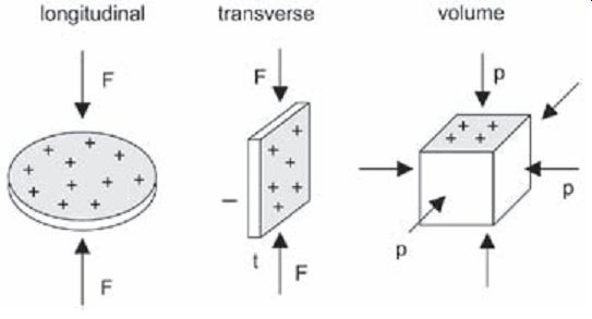
FIG. 2.1: Longitudinal cut (left): induced charge and applied force
share the same surface. Transverse cut (middle): charge is not induced
on the same surface on which the force is applied. Volume effect (right):
a hydrostatic pressure is applied to the sample, the charge being generated
on two opposite surfaces.
Both the longitudinal and the transverse effects are basically uniaxial. The pressure to be measured is converted into an uniaxial force by a diaphragm. The volume effect differs from the uniaxial effect in that the force is applied on all surfaces of the sensing element. The sensitivity is the sum of the longitudinal and the transverse contributions.
Volume effect: Q = (dL · p + 2 · dT · p)·AQ = dh · p · AQ
where dh is the hydrostatic piezoelectric coefficient and p the applied pressure. Note that the hydrostatic piezoelectric coefficient is always zero for quartz and all crystals having the same symmetry as quartz. The volume effect is mainly used in shock wave sensors or in hydrophone applications, where the direction of propagation of the pres sure wave is not known.
For the longitudinal, transverse and volume effects, the load is applied perpendicular to the piezoelectrically active surface. Shear cuts, where the load is applied parallel to the surface, could in principle be used, but would not significantly improve the properties.
Piezoelectric materials
The sensing element is the heart of the transducer and should hence be selected care fully. Electronic or software compensation for "bad" crystal properties are hardly possible. High sensitivity, high insulation resistance, high mechanical strength, high rigidity, low temperature dependence of the properties over a wide temperature range, low anisotropy, linear relationship between charge and mechanical stress, no aging, no pyroelectricity (insensitive to temperature changes), good machinability, low manufacturing costs-these are a few requirements for a good piezoelectric material.
Of course, the ideal material fulfilling all the criteria mentioned above does not exist.
Quartz has been used extensively in the past years and is still the material of choice for most pressure sensors. It is very stable, has a very high mechanical strength, can be used up to 400°C, has outstanding electrical insulation properties, has minimal sensitivity deviation up to 350°C (with special crystal cuts), is not pyroelectric, and is available at low cost. The only disadvantage of quartz is its relatively low sensitivity and its tendency to twin under very high loads.
Tourmaline has a lower sensitivity than quartz, but its temperature range extends to at least 600°C. However, it is pyroelectric and it is only available as natural crystals.
Lithium niobate and lithium tantalate have a higher sensitivity, but they are strongly pyroelectric and their insulation resistance is quite low, limiting their practical use to purely dynamic applications.
Crystals of the CGG group (typical crystals are Ca3Ga2Ge4O14 and langasite, for instance) have been intensively studied over the last 20 years. Belonging to the same crystal symmetry as quartz, they are not pyroelectric and possess a higher sensitivity.
Unlike quartz or gallium orthophosphate, they have no phase transition up to their melting point (above 1300°C), so that their properties remain very stable up to very high temperature and no twinning occurs. However the growth of large crystals is more difficult than for quartz, although langasite crystals up to 4 inches diameter have been grown.
Gallium orthophosphate has the same crystalline structure as quartz. Its sensitivity is twice that of quartz and is practically constant up to 500°C. Its phase transition lies around 970°C (573°C for quartz), extending the useful temperature range to at least 600°C. It is however very difficult to grow (the growth lasts a few months to one year) and is not available as large crystals.
PZT-based piezoceramics and Lead-Metaniobate have a very large piezoelectric sensitivity (up to 100 times that of quartz), but aging (time dependent depolarization), poor linearity and huge pyroelectric effect limit its use to applications for which accuracy is not critical.
High temperature piezoceramics (bismuth titanate based materials) can be used up to 500 or 600°C, but suffer similar (although not as serious) problems as PZT. Their sensitivity is about 5 to 10 times higher than that of quartz. They are used in high temperature applications (e.g., accelerometers operating up to 600°C).
Electronics
As already mentioned in the introduction, piezoelectric transducers are active systems (they do not require any power supply) which have a charge output (high-impedance output). For data acquisition and signal analysis, the charge output must be converted to a voltage, for instance by means of an electrometer or a charge amplifier.
Charge amplifiers
A charge amplifier is basically a high-gain inverting voltage amplifier with a very high input insulation resistance configured as an integrator. A typical measuring chain with a charge amplifier is shown in FIG. 2.2; examples of laboratory and industrial charge amplifiers are shown in FIG. 2.3.
The most common output voltage Uout is ±10 V. The range capacitors Cr can be switched usually between 10 pF to 100 nF, allowing for measurements over a wide charge range. A time constant can be switched on with the resistor Rt (usually 1 G ohm , 100 G ohm). The Reset/Operate (R/O) switch allows setting the zero point of the charge amplifier.
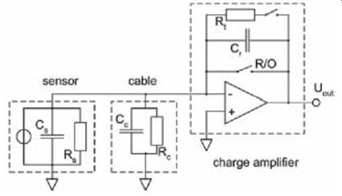
FIG. 2.2:
Measuring chain with charge amplifier. The sensor is modeled as a current
source (charge source) in parallel with the sensor capacitance Cs and resistance
Rs. The properties of the cable are described by a capacitance Cc and an
insulation resistance Rc. The charge amplifier consists of a high gain
amplifier with a range capacitor Cr, a time constant resistor Rt and a
reset/operate (R/O) switch.
The output voltage of the ideal charge amplifier (infinite open loop gain A, no leak age current, no offset voltage at the input) depends only on the induced charge and the range capacitor, where the input impedance has no influence.
Output signal
Uout = -Q / Cr
Lower frequency limit (-3dB) fl = 1 / (2p · Rt · Cr )
If no resistor Rt is selected, the charge amplifier operates in DC mode and the steady state behavior is governed by drift.
These relations are sufficient for most applications. In some extreme cases, the properties of the real charge amplifier must be taken into account:
Upper frequency limit fu = 200 … 500 kHz
When operating at frequencies above 100 kHz, the input impedance can no longer be neglected, as the open loop gain of the amplifier depends on frequency.
Drift due to leakage current IL < 10 fA (MOS-FET), IL < 100 fA (J-FET)
Leakage currents cause a drift in the output voltage, which eventually bring the amplifier to saturation. The time dependent charge QL = IL · t generates a time dependent output voltage Uout (t) = -IL · t / Cr.
Drift due to offset voltage and low input resistance
Uoff = a few mV
The offset voltage at the amplifier input induces a current Id = Uoff/ (Rs // Rc). As for leakage currents, this current may bring the amplifier into saturation. Some charge amplifiers have a built-in zero adjustment to keep the drift to a very low level.
Should the input resistance be very low (for instance when measuring at high temperature), switching on a time constant resistor Rt or adding a coupling capacitor in series between sensor and amplifier might solve the drift problem. In both cases, the lower limit frequency fl increases.
High input capacitance (> 1µF) U Q
In applications for which very long cables are needed, the cable capacitance cannot be neglected, in particular if the open loop gain of the amplifier is not very high. This results in a decrease of the output signal.
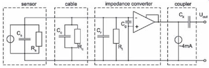
FIG. 2.4: Measuring chain with an impedance converter.
Impedance converters are very common in sensors with integrated electronics (sensors with voltage output or low impedance sensors). Compared to the charge amplifier, the impedance converter is a cost effective solution and is usually found in industrial applications. Conversely, the charge amplifier offers more flexibility: the output voltage does not depend on the input capacitance, the output voltage is proportional to the applied load, the pressure ranges can easily be switched, allowing any sensor to be connected to the same unit.
In FIG. 2.4, the sensor is modeled as a current source (charge source) in parallel with the sensor capacitance Cs and resistance Rs. The properties of the cable are de scribed by a capacitance Cc and an insulation resistance Rc. The impedance converter consists of an unity gain amplifier with a range capacitor Cr, and a time constant resistor Rt. The coupler powers the impedance converter with a constant current of about 4 mA. The capacitor Ck decouples the measuring signal from the offset voltage.
Noise suppression
Single-ended charge amplifiers are mostly used. They have a common path for one of the signal sides. In order to prevent ground loops, the system (sensor + amplifier) should be grounded at one point only. This solution usually provides a good signal-to noise ratio. For low level measurements in the presence of a strong electromagnetic field or when very long cables are needed, the differential charge amplifier may be required. Basically, the differential charge amplifier rejects unwanted signals present on both conductors (common mode rejection), as they amplify only the difference signal.
This requires sensors with equally balanced capacitances on each signal line.
Sensor Design and Applications
Basic design
Sensor housing
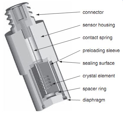
FIG. 2.5: Basic design of a pressure sensor for general applications.
The description of each component is found in the text.
The sensor housing protects the piezoelectric element against dirt and humidity. The housing also serves as an electrical shield. Further, it provides a means of mounting and sealing the sensor from the pressure media. The sealing area of the sensor is designed to meet the specific applications. All these requirements can only be met using hermetically sealed housings. The housing material is typically a precipitation hardened stainless steel.
Preload sleeve
Preloading the sensing element assures a good linearity and sensitivity stability of the sensor over its complete operating range. The preload must be assured over the entire operating temperature range. The wall of the preload sleeve may measure less than a tenth of a millimeter in thickness to optimize the elasticity and reduce the force shunt.
The material of the preload sleeve is usually made of the same material as the sensor housing. Not all sensors use a preload sleeve. Sometimes, the preload is provided by the diaphragm itself.
Diaphragm
The active area of the diaphragm converts the pressure into a proportional force acting on the element. This force generates a stress into the crystal yielding a proportional charge. Most diaphragms today are hermetically welded to the sensor housing and slightly preloaded or welded to the front end of the sensing element. The diaphragm is the most critical part of the pressure sensor. It determines the durability of the sensor and the accuracy of the measurements. It must be insensitive to brief thermal shocks (i.e., combustion engines) so as not to create measurement errors. In order to achieve superior results, diaphragms must be optimized for various applications.
Connector
The electrical connectors for piezoelectric sensors must have a very high insulation resistance. Depending upon the operating temperature range, the insulator is made of PTFE or aluminum oxide.
Spacer ring
This ring compensates for the difference between the thermal expansion of the crystal and preload sleeve material. By appropriate dimensioning and material selection, the ring effectively reduces temperature induced output drifts.
Crystal element
The shape and size of the piezoelectric crystals vary depending upon sensor design and application. The examples shown in Figures 2.5 and 2.6b use a design with three crystal elements using the transverse effect. The mechanically unloaded surfaces are metal vacuum coated and insulated from each other to form electrodes for collecting the electrical charge. A helical-shaped spring contacts the flat surfaces and carries the charge to the connector. The cylindrical side contacts the preloading sleeve.
Design of the piezoelectric sensing element
Today, sensing element designs can vary significantly to meet specific requirements such as pressure range, operating temperature and environmental considerations.
Crystal disks cut for the longitudinal effect (FIG. 2.6a)
Sensing elements using these plates can consist of one or several crystal plates. The sensitivity of these elements is directly proportional to the number of plates used. Further, these plates do not require metalized surfaces. The charge is collected directly from the loaded surfaces using electrodes. Such elements are used for high frequency (short rise time) or high temperature pressure sensors.
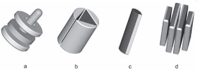
FIG. 2.6: Different crystal element design. a) is based on longitudinal
cuts. b), c) and d) are based on transverse cuts.
Set of crystals cut for the transverse effect (FIG. 2.6b)
In the transverse effect, the force is acting on the end faces and the electrical charge appears on the mechanically unloaded faces of the crystal. These faces are metal coated and insulated from each other. Depending on their size, a set of three crystals generates a charge equal to 5 to 15 piezoelectric disks of the longitudinal effect. These elements are ideal for small to medium sized pressure or force sensors and yield a high sensitivity.
Crystal rod cut for the transverse effect (FIG. 2.6c)
In this configuration, the metal coating of each unloaded surfaces extends to one of the end faces. The smaller sized crystal generates a charge equal to 4 to 6 piezo electric disks of the longitudinal effect. These crystals allow for very small sensing element designs.
Set of crystal plates cut for the transverse effect (FIG. 2.6d) Each of the four plates is similar to the crystal rod previously described. The set has a sensitivity of approximately 7 to 10 piezoelectric disks of the longitudinal effect.
However, with a plate thickness of only a few tenths of a millimeter, several plates are used in parallel to increase the load bearing capacity. This configuration is ideal for very small sensors.
Standard sensors for general pressure applications
Sensor with longitudinal crystal cuts --- Sensor with transverse crystal cuts
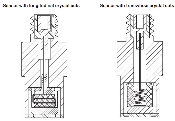
FIG. 2.7: Sensors for general pressure applications. Left: Design
with longitudinal cuts (crystal discs). Right: Design with transverse cuts
(crystal slabs).
Both sensors shown in FIG. 2.7 have the same sensitivity. While the sensor on the left is using crystals in the longitudinal effect and has a higher resonant frequency (approx. 300 kHz), the sensor on the right is using crystals in the transverse effect, and is therefore essentially insensitive to the twinning effect in quartz. The crystals can be cut in certain ways to optimize the temperature coefficient of sensitivity. Sensors using the longitudinal effect of quartz should not be used for high-temperature applications.
Sensor manufacturers offer a large selection of optional mounting hardware such as: adaptors, connecting nipples, etc. This allows a small number of sensor types to be used effectively for many applications. In situations where space is limited, sensors can be installed directly without the need for an adaptor.
Sensors are available in various sizes. Smaller versions have an outer diameter of 6 mm, the larger ones 11 mm. While the smaller sensors have a sensitivity of 16 pC/bar, the larger produce 80 pC/bar with measuring ranges from 250 bar to 1,000 bar. It is worth noting that piezoelectric sensors have a very large dynamic measuring range.** Acceleration compensation All pressure sensors are sensitive to acceleration, especially in the axial direction.
In high vibration environments with small pressures levels, the acceleration induced signal can reach a few mbar/g. While in most applications the acceleration error can be ignored, it can disturb measurements where the sensor is subjected to strong vibrations while measuring small pressure. In such applications (e.g., acoustic or sound level detection), acceleration compensated sensors should be used.
Acceleration compensated pressure sensors may use longitudinal or transverse effect crystals.
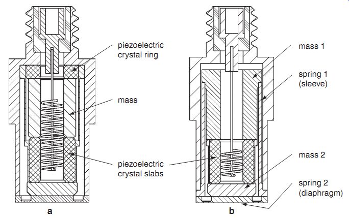
FIG. 2.8:
Design for acceleration-compensated sensors. a): traditional design, b):
new design. ** The same sensor can be used for a partial measuring range
of 1 bar as well as for a full range of 1000 bar.
Traditional design (FIG. 2.8a):
The helical-shaped spring connects the charge from the set of crystal slabs to the mass. The crystal ring is installed with opposite polarity to the transverse effect crystals, thereby reducing the pressure sensitivity of the sensor. The compensating mass is dimensioned so that the crystal ring produces the same, but opposite signal acting on the transverse effect crystals. Under acceleration, the signals originating from the two sets of crystals cancel each other. Acceleration compensation adds complexity to the sensor, but a recent design achieves acceleration compensation without the crystal ring.
New design (FIG. 2.8b):
In this new patented design, the two spring-mass systems are adjusted to be equal eliminating any acceleration-induced forces to act on the crystals. The vibration sensitivity of these designs is typically smaller than 100 µbar/g.
Ground insulated pressure sensors
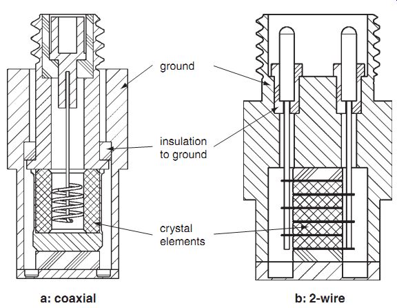
FIG. 2.9: Ground insulated sensors. a): coaxial design. b): 2-wire design.
Ground isolated sensors reduce ground loop hum which arises when big potential differences build up between the sensor and the measuring chain (electronics). This may happen when electronics and sensors are connected with very long cables. In the coaxial design (FIG. 2.9a), the outer shield of the coaxial cable is not electrically connected to the sensor housing. The two-wire system (FIG. 2.9b) requires true differential design of the piezoelectric measuring elements and also needs a true differential charge amplifier. These sensors are primarily used in high to very high temperature applications in gas turbines, aeronautic and aerospace applications. Most of these sensors are also acceleration compensated.
Sensors for ballistics (high pressure)
Piezoelectric pressure, force and acceleration sensors have been used for many years for ballistics measurements. About fifty years ago, the first piezoelectric pressure sensors used for ballistics had a mechanical piston instead of a diaphragm. These sensors had to be disassembled and cleaned after every shot. Today, piezoelectric high-pres sure sensors are used worldwide for acceptance testing of ammunition and gun powder. These tests assure that the ammunitions pass the stringent pressure profile requirements specified by the gun manufacturers.

FIG. 2.10: Typical design for a ballistics sensor. The thread is
separated from the crystal element (Anti-strain design). Available with
M10 to M12 thread.
Today, front sealing sensors have replaced the shoulder sealing sensors. FIG. 2.10 shows a front sealing "Antistrain" pressure sensor. This design eliminates measurement errors caused by the mechanically induced mounting strain. Further, the Antistrain design also eliminates sensitivity variations due to varying mounting torque. The measurement range for ballistic high-pressure sensors range from 5,000 bar to 10,000 bar with a linearity of less than ±0.5 % full scale with excellent long-term sensitivity stability. The life expectancy is several thousands of pressure cycles. As with any piezoelectric sensors, the same ballistic pressure sensor is capable of measuring a few 100 bar up to 10,000 bar.
Older designs required the user to apply periodically a protective coating of grease to the diaphragm to protect it from the hot gases. New sensor designs are capable of measuring accurately with an excellent life expectancy without the need for protective coatings.
Cavity pressure sensors
Measuring the cavity pressure in molds of plastics injection machines improves the quality and reduces the production time cycles. Optimizing this process assures that the parts have a constant weight and remain dimensionally stable. Continuous monitoring of the pressure profiles during molding improves yield resulting in reduced production cost.
Special pressure sensors were developed for these applications. Contrary to conventional sensors, they do not have a diaphragm (FIG. 2.11). As the hot plastics material contacts the relatively colder cavity of the mold, the plastic immediately forms a skin acting as a diaphragm, hence preventing the hot material from penetrating the less than 0.03-mm wide gap between the measuring element and the mold.
This eliminates the need for a diaphragm that would limit the life expectance of these pressure sensors. Further, the front end of these sensors can be shaped to conform to the surface of the mold.
Most sensors are mounted directly into the mold without the addition of a protective sleeve. This reduces the size of the sensor, making it suitable in molds used for very small parts. Direct mount sensors have typically diameters from 4 to 8 mm (FIG. 2.11a), the smallest has a diameter of only 1 mm.
Cavity pressure sensors operate reliably in temperatures up to 200°C. Although the mold temperature limits the functionality of the sensors, the actual melt tempera ture of the material can be higher (400°C). Most of the sensors include an integrated O-ring to reduce contamination that often lodges between the sensor element and the mold, but this is not essential for the proper operation of the sensors.
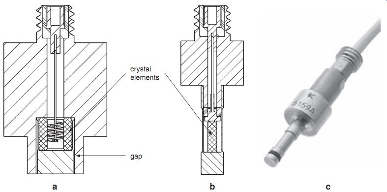
FIG. 2.11: Sensors for cavity pressure measurements. a): front diameter
6 mm. b) and c): front diameter 2.5 mm.
Sensors for engines
Piezoelectric pressure sensors were used early on to measure combustion pressure in engines. Today, most piezoelectric pressure sensors are used for the development of automotive engines. New sensors are being developed continuously to meet the higher demands for smaller engines and higher accuracy.
The typical operating temperature varies between 150 to 350°C depending on measuring location and test conditions. However, the diaphragm temperature can be considerably higher. The diaphragm is exposed directly to the hot cyclic combustion gases of approximately 2,500°C. Special diaphragm designs and materials minimize thermally induced measurement errors and assure high life cycle durability. Meeting these requirements pose special challenges to the diaphragm design and demands that the sensors must be optimized for specific applications.
Today's combustion engines are becoming smaller and have four or more valves per cylinder. This limits the space available for the combustion pressure sensor. Sensors with an M5 mounting thread and a front diameter of 4 mm make these installations possible (FIG. 2.12a). For further space restricted applications, sensors can be integrated directly into specially designed spark plugs or glow plugs (FIG. 2.12b).
Water-cooled sensors improve zero stability (FIG. 2.13a). Initially, water cooling of the sensors was required to protect the sensors from the high temperatures of the engines. Modern sensors can be used without water-cooling, hence will not be dam aged if for some reason the cooling is interrupted. The smallest water-cooled sensor today has an M8 mounting thread.
To monitor large diesel and gas engines for power stations and ships, robust, uncooled pressure sensors are used. These sensors are designed for continuous operation and feature a long lifetime (FIG. 2.13b). Often, the measurement systems include an integrated charge amplifier customized for specific applications.
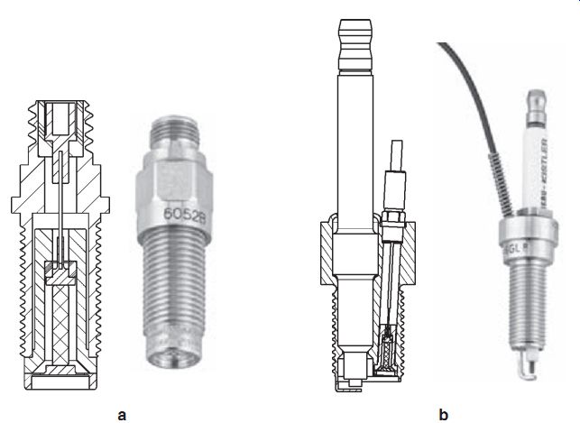
FIG. 2.12a: Combustion pressure sensors with an M5 mounting thread.
FIG. 2.12b: Small pressure sensor integrated in a M12 spark plug.
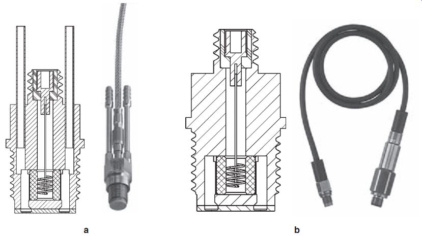
FIG. 2.13a: Water-cooled pressure sensors M8 for engine applications.
FIG. 2.13b: Robust uncooled sensor M10 for engine monitoring.
High-temperature pressure sensors
The gas turbine manufacturers need high-temperature pressure sensors able to operate at temperatures higher than 400°C in order to monitor small fluctuations of the combustion pressure. Sensors operating up to 650°C with a pressure range of 0 .. 250 bar are available (FIG. 2.14). To withstand these high temperatures, the sensing part of the sensor is made of tourmaline discs and the sensor is fitted with a two-wire mineral insulated cable. The sensor design is similar to FIG. 2.9b.
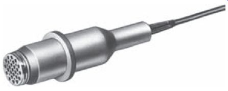
FIG. 2.14: Transducer for operating temperatures up to 650°C.
Sensor Selection
The sensor manufacturers can help you find the most appropriate sensor for your application. Data sheets are nowadays available on the internet and together with search functions or application oriented tools greatly facilitate the search for the right sensor.
Hereafter is a list of the most relevant sensor and electronic properties you need to know before starting a search:
Sensor
Pressure range - the maximum pressure the sensor will have to measure.
Calibrated partial range - useful for measurements in a smaller pressure range.
Note that piezoelectric sensors offer several decades of measuring range without loss of accuracy.
Overload - the maximum pressure the sensor will have to withstand.
Natural frequency - This defines the upper frequency limit of the dynamic pressure signal.
Sensitivity - the sensitivity of the sensor (usually in pC/bar or mV/bar).
Thermal sensitivity shift - the variation of sensitivity as a function of temperature.
Linearity - usually in ±%FS (full scale). Deviation from a true linear relation ship between output signal and pressure.
Hysteresis - usually in %FS (full scale). Output difference when the same increasing and then decreasing pressure is applied consecutively.
Insulation resistance - a sensor with good electrical insulation properties will allow measurements down to the mHz range. Note that the electrical insulation of the sensor decreases as the temperature increases.
Temperature range - the minimum and maximum operating temperatures. If the temperature exceeds 300°C, special attention is needed for the connector and the cables.
Sensor dimensions - the maximum allowed dimensions of the sensor (mounting hole).
Shock resistance - the maximum shock resistance (usually in g).
Acceleration sensitivity - relevant if the sensor is mounted on a vibrating structure (engine for instance). One distinguishes radial and axial acceleration sensitivities.
Thermal shock - output signal (usually in bar) due to a thermal shock on the sensor. Important in engine measurements.
Environment - usually the sensors are hermetically sealed and made of stain less steel. Special attention is however required if you intend to use the sensor in a very corrosive or abrasive medium, or if the sensor will be submitted to nuclear radiations.
Connector and cables - low-noise coaxial cables (charge output), standard coaxial cable (voltage output).
High-temperature applications (> 300°C) require special cables and connectors.
Sensor output - charge or voltage output. Voltage output is achieved by integrating the electronics in the sensor. The advantage is that you do not need any additional electronics (charge amplifier), but the flexibility is greatly reduced, as only one pressure range and one time constant are available.
The temperature is limited to about 150°C.
The lower frequency limit depends basically on the range capacitor and the range resistor. Let us assume that you have the following configuration:
Sensitivity of the pressure sensor: 20 pC/bar
Pressure range: 200 bar
Full scale output: 10 V
First you have to select the range capacitor. The output sensitivity (sensitivity of the charge amplifier) is given by:
20 pC/bar · 200 bar / 10 V = 400 pC/V
This is also the ideal value of the range capacitor Cr = 400 pF. Of course, a real charge amplifier is not configured with thousands of range capacitors, but only with 4 or 5 very precise decade capacitors (100 pF, 1, 10, 100 nF, for instance). In our example, the effective range capacitor is the next higher capacitor, i.e., 1 nF.
In AC mode, the time constant, t, depends on the product Rt · Cr .
Assuming Rt = 100 G?, the time constant is now t = Rt · Cr = 100 s and the lower frequency limit (3 dB amplitude decrease of a sine wave) is computed according to fl = 1 / (2p ·t) = 1.6 mHz
Latest and Future Developments
Today's development is driven mainly by two factors: miniaturization and high temperature. These two factors have been pushing the research for new piezoelectric materials with better properties: higher sensitivity and good stability at high tempera ture (>300°C). As a result, new materials belonging to the CGG group are replacing the standard materials (quartz and tourmaline) in miniature or high temperature sensors.
Miniaturization
Sensors have to be smaller. This is a consequence of the trend observed in many application areas. For instance, engines are always more compact, requiring sensors of diameters M5 or even smaller. In injection molding of plastics, sensors with diameter 2.5 mm for pressure measurements up to 2,000 bar are now commonly used.
Reducing the size of sensors is a challenging process. Apart from the difficulty of manufacturing small sensor components, the sensitivity decreases proportionally to the diaphragm area. As the diameter decreases, the force acting on the piezoelectric element decreases with the square of the diameter. Accordingly, reducing the diameter of the sensor (diaphragm) by a factor of two results in a sensitivity drop by a factor of four. This may be overcome by cutting very thin slabs of crystals and using the geo metrical factor in transverse crystal designs to enhance the sensitivity or/and by using materials with higher sensitivity.
High temperature
Standard pressure sensors can be used today up to 350°C. Above this temperature, many problems have to be overcome: the piezoelectric element has to be stable and still maintain high insulation, corrosion can be avoided by using nickel-based alloys (but they are difficult to machine or to weld), conventional cables have to be replaced by integrated metal cables, etc. Of course, the sensor must withstand these temperatures often over thousands of hours, as the machines (turbines for instance) cannot be stopped at will to replace a defective sensor. Some manufacturers offer sensors operating up to 600 or 700°C, based on tourmaline, lithium niobate or high-temperature piezoceramics.
Sensor identification
Each sensor is calibrated by the manufacturer and comes with a so-called calibration sheet. Before using the sensor, the operator has to enter the correct sensor sensitivity in the charge amplifier. For applications requiring many sensors, this may be a tedious task and a mistake is possible. Sensor identification, coupled with a database containing all the needed information (ID, sensitivity, sensitivity shift under temperature, etc.) has now become available and greatly facilitates the implementation of large numbers of sensors. One way is to integrate a TEDS (Transducer Electronic Data Sheet, according to IEEE 1451.4 Standard) digital chip in the sensor or its connector.
When plugging the sensor to the charge amplifier, the data is read from the TEDS and the charge amplifier automatically adjusts its parameters according to the sensor sensitivity. TEDS are rewritable, allowing subsequent modifications or adaptations of the sensor properties. Another way is to integrate an ID chip (for instance a coded surface acoustic wave (SAW) tag) in the sensor. The charge amplifier recognizes the sensor and can get the relevant information in a database, provided it is connected to a PC.
References and Resources
1. Bill B., "Messen mit Kristallen," Die Bibliothek der Technik, Band 227 (2002) or "Measuring with crystals," Kistler V900-335e.
2. Cavalloni C., & Sommer R., "PiezoStar Crystals: A New Dimension in Sensor technology," Kistler Special Print 920-240e-07.03 (2003).
3. Gautschi G., "Piezoelectric Sensorics," Springer (2002) and references therein.
4. IEEE Standard on Piezoelectricity (ANSI/IEEE Std 176-1987).
5. Ikeda T., "Fundamental of Piezoelectricity," Oxford University Press (1996).
6. Krempl P.W., Schleinzer G. & Wallnöfer W., "Gallium Phosphate GaPO4: A New Piezoelectric Crystal Material for High-Temperature Sensorics," Sensors and Actuators A61, 361-363 (1997).
7. Tichy J. & Gautschi G., "Piezoelektrische Messtechnik," Springer (1980).
8. Wilson J., "Noise Suppression and Prevention in Piezoelectric Transducer Systems," Endevco TP 270.
NEXT: Sensors for Mechanical Shock
PREV: