AMAZON multi-meters discounts AMAZON oscilloscope discounts
At the first Shock and Vibration Symposium in 1947, mechanical shock was defined as "a sudden and violent change in the state of motion of the component parts or particles of a body or medium resulting from the sudden application of a relatively large external force, such as a blow or impact." Since then the specific words used have changed somewhat but the meaning remains the same. Most analysts treat shock as a transient vibration. No matter how it is described or what source produced it, the effects of mechanical shock on structures and equipment create major design problems for a wide variety of systems.
1. Technology Fundamentals
Shock measurement is usually accomplished by measuring the acceleration, velocity, or displacement response of the body. Shock measurement is important in studying the effectiveness of protective packaging design, earthquakes, effects of explosive events (pyroshock), effects of handling and or dropping items, transportation environments, many military applications, automotive crash testing and ballistic effects.
Shock Measurement
Shock measurement usually requires good high frequency response, good linearity and a wide dynamic range. Frequency content can reach 100 kHz and higher, and amplitudes may exceed 100 kg (˜10^6 m/s^2 ). Long duration transients may also require good low-frequency response. Two basic categories of shocks may have to be measured, velocity shocks and oscillatory shocks.
Velocity Shocks
Velocity shock has two components: intensity, usually measured in g's (1 standard g = 9.80665 m/s^2 ), and duration, measured in milliseconds. A drop from table-top height onto a hard floor can result in shock in excess of 1,000 g's over a period of about 3 milliseconds. A component in an artillery shell experiences about 16,000 g's for 12 milliseconds. Higher shock levels usually have shorter duration, perhaps fractions of milliseconds, and lower shock levels can have a duration as long as 20 milliseconds.
Shocks resulting in crushing or bending of impact surfaces may last hundreds of milliseconds.
Oscillatory Shocks
Oscillatory shocks, such as pyroshock and ballistic shock are shocks that do not cause a significant change of velocity of the object experiencing the shock. Instead, they cause an oscillatory response or ringing. For example, hitting a large bell with a hammer will cause the bell to oscillate (ring) but will not significantly change the bell's velocity.
High Amplitudes
Many shocks involve large forces and result in high amplitude acceleration response.
Accurate measurement requires a wide dynamic range and good linearity.
Low level (less than 100 g's) can usually be measured using general-purpose accelerometers. Higher peak acceleration levels will usually require accelerometers that have been designed specifically for shock measurements.
Shock accelerometers have lower sensitivities and higher resonance frequencies than general purpose accelerometers. And, of course, they are designed to survive many applications of the high internal stresses caused by high amplitude shocks.
High Frequencies, Short Rise Times
Shock transients often have very short rise times requiring good high-frequency response and minimal ringing. Pyroshock measurements may require physical mitigation of extremely high frequencies that excite accelerometer resonance frequency. If the accelerometer survives the mechanical stresses of the resonance, it will produce an excessive output signal level which may overload signal conditioning causing clipping and loss of data. Mechanical filtering combined with electrical filtering can minimize these problems, but the characteristics of the mechanical and electrical filters need to be well-matched to prevent distortion in the frequency range of interest (usually up to 10 kHz).
High Sensor Stresses
The sensor measuring the shock must not only be able to survive it, but also to maintain its accuracy and linearity for many repetitions of similar shocks. Internal stresses in the sensor may cause shifts in performance characteristics, cumulative damage, fatigue failures, nonlinearities, or other problems. Some of the symptoms of such damage are significant changes of resistance and/or capacitance, excess noise, change of zero measurand output, and change of sensitivity.
2. Sensor Types, Advantages and Disadvantages
Shock is commonly measured with an accelerometer or velocity sensor measuring the response of the device under test as it responds to the transient force input. Non contact measurements may be made using optical techniques such as laser Doppler velocimetry. Occasionally, strain gages are used to directly measure the strain(s) induced in a structure by the shock transient.
Piezoelectric Accelerometers
Piezoelectric accelerometers, described elsewhere in this handbook, have proven to be very popular for many shock measurement applications because of their inherent ruggedness and wide variety of characteristics available. Although mechanical structures vary widely (compression, annular shear, flat plate shear, etc.), they can be divided into two basic types, charge mode (high output impedance) and internal electronic (low output impedance).
Charge Mode (PE)
Charge mode accelerometers are used with an external charge amplifier or in-line impedance converter that senses the charge generated by the strain of the PE crystal.
Their output is measured in picocoulombs and must be very carefully transmitted using well-shielded low noise coaxial cable. If the cable is not treated for triboelectric noise or not well-shielded, the cable noise or electromagnetic interference noise may seriously corrupt the signal.
Charge mode accelerometers are inherently the most rugged and most reliable be cause of their simplicity of design and construction.
Internal Electronic PE (IEPE)
Internal electronic piezolectric (IEPE) accelerometers incorporate a preamplifier in the accelerometer case. Their output is pre-amplified and has low output impedance.
It is, therefore, less susceptible to environmental noise and cable noise. However, including electronic components, with multiple electrical connections, inside the accelerometer reduces their inherent reliability. Also, the internal electronics has a fixed gain which determines the dynamic range of the sensor. This limits the flexibility of application.
Piezoresistive Accelerometers (PR)
Modern piezoresistive (PR) accelerometers are manufactured using MEMS (micro electro mechanical systems) technology. Those designed for shock measurement typically have semiconductor strain gages implanted into complex spring-mass structures. Their primary advantage over other types of accelerometers is that they have frequency response down to DC (steady state, infinite low-frequency time constant). Therefore they can be used to measure very long duration shocks with no degradation of fidelity. When this steady state responding characteristic is combined with high resonance frequency, low sensitivity capability, an ideal shock measurement sensor results. MEMS technology enables this combination of characteristics to be realized in a relatively small physical size sensor.
The biggest disadvantage of PR accelerometers is their relative fragility if excited to resonance. Since their seismic systems have mechanical amplification factors up to 100 at resonance response, even a small amount of excitation energy near their natural frequency will cause excessive response with high stresses and likely breakage.
Therefore, PR accelerometers must be very carefully applied in shock measurement applications.
Laser Doppler Velocimeters
Laser Doppler velocimeters measure the Doppler shift in the frequency of a modulated laser beam reflected from a target surface. The reflected beam is compared with the incident beam and the frequency shift is used to determine the velocity of the target.
Since this is a non-contact measurement, it can sometimes be used where a sensor could not be mounted. It also eliminates the possible errors caused by mounting and mechanical effects in a contact sensor.
Disadvantages are that the instrument is relatively large and expensive and the measurement requires a line of sight be established between the velocimeter and the target. Some velocimeters have specific stand-off requirements restricting the geometry of a test setup.
Strain Gages
Because the objective of many shock tests is to try to determine stresses in the subject structure, strain gages are often used instead of, or in addition to, other sensors. They can be located and oriented to directly measure strain in critical areas. However, they do not characterize the shock transient or the structural response of the device under test (DUT). Strain measurements may be affected by local flaws or discontinuities in the structure.
3. Selecting and Specifying
Applications such as package drop-testing, automotive crash-testing, and pyroshock / simulation require accelerometers with special capabilities. An accidental drop of a cellular phone from standing height can produce peak acceleration levels well over 10,000 g's. Many novices in shock testing make the wrong assumption that the shock measurements of an object can be approximated using a rigid body model, and completely forget about the localized material responses. In a high-g shock test where structural responses are often nonlinear and difficult to characterize, choosing the right accelerometers can be critical. In addition to the characteristics of the shock to be measured, other environmental effects must also be considered. Basic accelerometer selection considerations for shock measurement follow.
Expected Amplitude
Range - Usable output range should not be confused with survivability. An accelerometer may only have to measure 100g full scale, but it may be required to survive an initial shock of 10,000g preceding the lower level event. Another distinction should be made between the maximum expected level from a Shock Response Spectrum and the actual input spectrum the accelerometer is likely to experience.
Low-pass filtering - Low-pass filters can be used at the input of an amplifier to pre vent overload condition due to unexpected input spikes.
Zeroshift - Zeroshift or DC-offset, a sudden change of baseline level during a high-g event (see FIG. 3.1), is a type of error usually associated with, but not limited to, PE/ISOTRON accelerometers. There is no universal standard for this parameter, so it cannot be found in the Performance Specifications. PR devices designed for high-g shock are typically immune from zeroshift. Accelerometers with a built-in mechanical filter, such as Endevco Models 7255A and 7270AM6, are designed to eliminate this problem. FIG. 3.1 illustrates the principle of a built-in mechanical filter. There have been several papers written on this subject; readers are advised to refer to Endevco Technical Paper TP290 and TP308.
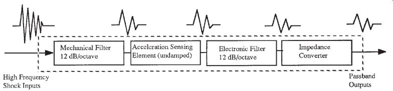
FIG. 3.1: Model for accelerometer with built-in mechanical filter.
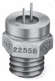
FIG. 3.2: Shock accelerometer with solder terminals.
Survivability - In lower level shock applications, most accelerometers can survive the environment without causing internal damage. But in high-g testing, physical dam age to the sensor is often a reality. It is suggested to overestimate the maximum shock level when selecting the range of a shock accelerometer. A general rule-of-thumb: the closer the accelerometers are to the source (explosive or impact), the higher the input g level. Survivability extends to cables and connections. In high-g shock, a small amount of unrestrained mass would translate into large force, causing connector failures (or bad contacts) and generating triboelectric noise with ordinary coaxial cable.
Solder terminals (see FIG. 3.2) and ribbon wires are recommended in high-g applications because of their light weight, but extra care is required in installing and handling these delicate connections.
Expected Frequency Content
As will be shown, the frequency content of the transient to be measured can vary widely. Especially when measuring shock, frequency extremes-both low and high- should be considered.
Low Frequency
When measuring long duration shock or measuring rigid body motion of the structure (i.e., ship shock), accelerometers with DC response are required to capture the low frequency information accurately. If the acceleration data is to be integrated to yield velocity or displacement information, DC response is an absolute necessity. Low frequencies may be contaminated by thermal transient response, discussed later in this SECTION.
High Frequency
The input spectrum of high g-shock, be it mechanical or pyrotechnic, has always been underestimated by practitioners in the measurement industry, leading to improper test equipment selections. Furthermore, most transducer manufacturers have very limited experience in high-g shock test, and it is reflected in the design approaches of many so called "shock" accelerometers. This author suggests that, in close range (near-field) high-g shock measurement, the accelerometer must be protected from all ultra-high frequency input energy in order to avoid sensor resonance, which is the root cause of many problems in high-g shock measurement.
All undamped, spring-mass type accelerometers have a finite seismic resonance.
When the resonance of such a device is excited, integrity of the output signals is suspected. To ensure linear response and minimize error, spectrum of the acceleration input must stay within the transducer's recommended bandwidth. As a general rule of-thumb, the maximum usable bandwidth for an undamped accelerometer is to be less than one-fifth of the transducer resonance. This rule is generally well observed in the vibration test community, but not so well observed in shock measurements.
Unfortunately, the term "maximum usable bandwidth" is often mistaken for the avail able bandwidth of a Shock Response Spectrum by many test engineers. Since most Shock Response Spectra stop at 10 kHz or 20 kHz, accelerometers with resonance in the neighborhood of 100 kHz are considered adequate for high g-shock applications, ignoring the fact that there is much energy beyond 20 kHz. The problem is further complicated by the issue of damage potential of high frequency. It is a well established fact that shock energy above 10 kHz seldom causes any damage to the test article, and it is routinely overlooked in most data analysis. These high frequency components, although posing no danger to the article, seriously affect the linear operation of any spring-mass type accelerometer.
It has been demonstrated that the input spectrum of most high-g shock measurements contains frequency components for above 100 kHz. These high-frequency components tend to cause resonance of almost any real structure, including accelerometers.
A few papers and articles have been published concerning the effect of ultra-high frequency impulses on shock measurements. This out-of-band transient phenomenon is referred to in the papers as a "Pre-Pulse" stress wave that approximates a true-impulse.
Two types of shock simulations are capable of generating near true-impulses
a) Close-Range (Near-Field) Pyrotechnic Shock
In pyrotechnic shock, the process of explosion involves chemical reactions in a substance which convert the explosive material into its gaseous state at very high temperature and pressure. Most explosives, such as Flexible Lin ear Shaped Charge and pyrotechnic bolts, do not contain as much energy as ordinary fuel, but generate an extremely high rate of energy release during explosion. The response of the structure near the immediate region can actually approach a true impulse due to the instantaneous velocity change at the explosive interface. As a result, measuring the data in the area surrounding a pyrotechnic explosion has always been a nightmare for engineers and scientists.
Depending on the explosive location and the point of measurement, the amount of high-frequency energy reaching the transducer is inversely proportional to the distance between them. In a remote sensing location where the shock wave has to propagate through a long path or many joints of dissimilar materials to reach the transducer, high-frequency components can be significantly attenuated.
b) Close-Range (Near-Field) Metal-to-Metal Impact
Most shock simulation devices, such as drop towers and pneumatic hammers, rely on high velocity metal-to-metal impact to generate the required shock spectrum. When the point of impact allows very little material deformation (like in all reusable shock machines), the acceleration response of the structure can also approach a true impulse. Again, the input spectrum is highly dependent upon the accelerometer location relative to the point of impact.
Failure Modes
Although these common methods of shock simulation present a formidable challenge for the entire measurement system, from sensor to data capture, the accelerometer is by far the most vulnerable under such conditions. There are two types of widely used shock accelerometers: piezoresistive and piezoelectric devices. Each reacts differently under the attack of near true-impulses. Three common failure modes are observed:
a) Sensor Failure
Recent new designs in piezoresistive accelerometers have tremendously improved their usable bandwidth and rigidity. One piezoresistive sensor (Endevco Model 7270A) exhibits seismic resonance above 1 MHz, leaving quite a large margin of safety for the general rule-of-thumb. Under the at tack of true-impulses, however, the sensor can still be set into resonance (at 1 MHz) due to the nature of the input signals. Since the gauge mechanism is practically undamped, displacement of the elements goes out of control at resonance and eventually causes permanent gauge damage. The result of this type of failure is complete loss of data.
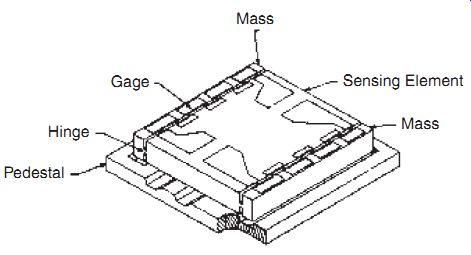
FIG. 3.3: Sensing element of high-resonance frequency PR accelerometer
.
Piezoelectric sensors are more robust under the same conditions, but they fail in other fashions:
b) Zeroshift
This subject has been well examined in many technical papers. A piezoresistive accelerometer generally does not exhibit zeroshift until the gauge mechanism has been damaged or, is in the process of deterioration. Piezoelectric sensors, on the other hand, account for most of the zeroshift phenomena associated with transducers.
When a piezoelectric element is set into resonance, three things can happen:
1. Relative displacement of the sensing element at its resonance can exceed 100 times of the input. Internal stress at the molecular level is therefore unusually high. This overstress condition produces spurious charge out puts due to domain switching, a characteristic common in polycrystalline materials. The result of this type of phenomenon is DC offset in the time history, as shown in FIG. 3.4.
2. Crystal elements that have monocrystalline structure do not exhibit domain switching phenomenon, but they produce zeroshift in another fashion.
Most monocrystal (such as quartz) shock accelerometers are compression type design, as depicted in FIG. 3.5. In this type of design, the sensor assembly is held together by a preloaded screw. When the transducer is excited into resonance, the amount of relative displacement between the components can actually result in shifting of their original positions. These physical movements of sensor parts cause a sudden change of the preload condition and manifest themselves as hysteresis effect-zeroshift at the output.
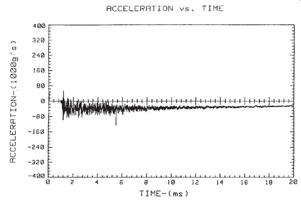
FIG. 3.4: Zero shift caused by shock transient.
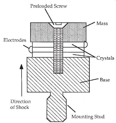
FIG. 3.5: Compression type accelerometer.
3. The crystal material is not overstressed, and no physical shifting of parts occurred, but a huge amount of charge is generated simply due to sensor resonance. This unexpected amount of electrical signal can saturate, or in many instances, damage the subsequent signal conditioners. The result of this type of malfunction is loss of data or gross DC offset in the time history.
Slight amount of zeroshift in the time history can yield unrealistic velocity and displacement during data reduction. The real danger remains that, although data with gross DC offsets are generally discarded, the minor offsets in the acceleration data (mostly unnoticeable by naked eyes) are accepted as good measurements.
c) Nonlinearity
The output of a transducer at resonance is sometimes nonlinear and not repeat able. The response of a saturated charge converter is also nonlinear and not repeatable. The result of this type of malfunction is poor repeatability in SRS, leading to incorrect definition of the shock environment.
Structural Resonance
Shock inputs with fast rise times (near true impulse) will often excite several resonant modes of the device under test (DUT) as well as the natural frequency of the accelerometer. If resonant modes of the structure are at frequencies near the natural frequency of the accelerometer, a multiplicative effect occurs. The structure multiplies the input by the Q of the DUT and that multiplied response becomes the input to the accelerometer. Thus the Q of the DUT is multiplied by the Q of the accelerometer.
Although this is the true response of the DUT (at that location), the double amplification may be sufficient to damage the accelerometer or force it into a nonlinearity.
Environmental Effects
As with any measurement, shock sensors respond to their total environment. Although sensor designers attempt to minimize response to non-shock inputs, there will always be some environmental effects on the measurement. The most common environmental effects are caused by temperature, thermal transients, transverse motion and electro magnetic interference.
Temperature
The sensitivity of an accelerometer varies as a function of temperature. Normal calibration data is applicable at +20°C. If an accelerometer is to be used at other temperatures, its expected responses should be understood. Since most laboratory shock test measurements are made at or near room temperature, this is often not of any consequence. However, if field shock measurements are to be made at temperatures significantly different from "room temperature," temperature sensitivity may be of concern.
For piezoelectric accelerometers, sensitivity variation with temperature is primarily a function of the change in properties of the piezoelectric material. A design is usually specified for operation over as wide a temperature span as stability and structural integrity permit. Over this range it will have a characteristic response, and individual variations from that will depend on material parameters, assembly and part variations.
A typical sensitivity plot for a temperature-compensated accelerometer is shown in FIG. 3.6.
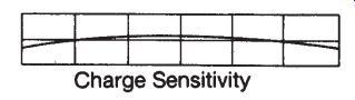
FIG. 3.6: Typical temperature response curve of compensated accelerometer.
[...]
most shock events are completed in such a short time. However, these outputs must be considered if the amplifier passes these low frequencies (usually less than 1 Hz) or if the outputs are sufficiently large that they would overload the amplifier. The amplitude and frequency content of thermal transient response is a function of the magnitude and rate of change of temperature. The pyroelectric characteristics of piezoelectric crystals are known and the output for any particular accelerometer-amplifier combination can be experimentally determined under specified temperature transient conditions.
There are three mechanisms that cause thermal transient outputs; they are called primary, secondary, and tertiary pyroelectric effects. The thermal transient response of an accelerometer is the resultant of all three.
Primary pyroelectric effect is the output caused by uniform temperature change in a constrained crystal. It occurs on surfaces perpendicular to the axis of polarization.
Some natural piezoelectric crystals (e.g., quartz) do not produce primary pyroelectric output. Compression designs using ferroelectric ceramics have a large primary out put. On the other hand, ferroelectric shear accelerometers do not produce a primary pyroelectric response because their electrode surfaces are parallel to the axis of polarization. Their pyroelectric response is comparable to natural crystals.
Secondary pyroelectric response is caused by thermal deformation of the crystal from uniform heating. Some natural crystals (e.g., tourmaline) have a large secondary out put, but still small compared to ferroelectrics.
Tertiary pyroelectric response is produced by all accelerometers. It is caused by a temperature gradient across a crystal. The tertiary component is dependent on mechanical design, polarization axis, and electrode orientation, not on the specific crystal material. In shear designs, the crystal elements are usually well isolated from the case structure so that thermally induced case strains do not produce an output. This, plus the absence of primary pyroelectric response, makes shear type accelerometers less affected by transient temperature changes than compression types. The Endevco Isobase design isolates the crystal from the accelerometer base, and decreases the thermal conductivity from the environment to the crystal. The Isobase design reduces the pyroelectric output by approximately one order of magnitude. The use of low-frequency roll-off in amplifiers will reduce the amplitude of slowly varying pyroelectric outputs to an insignificant level and block any steady state outputs. In most applications, amplifiers with a low-frequency cut-off of 3 Hz or above will have no significant output errors caused by pyroelectric effects. However, amplifiers with extended low-frequency response can pass some transient pyroelectric signals.
ANSI recommends a pyroelectric test procedure for the complete transducer-amplifier combination. In this procedure, the transducer is mounted on a test block whose mass is much greater than the transducer mass. The test block and the transducer are then subjected to a sudden 50°F ambient temperature change while the amplifier output (FIG. 3.7) is monitored.
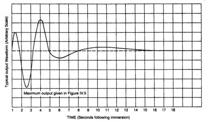
FIG. 3.7: Thermal transient response of accelerometer.
The results of such a test on various transducers are presented in Table 3.1. Two different methods are compared in Table 3.1. In the older method, only the mounting block was immersed; in the newer method the block and the accelerometer are both immersed.
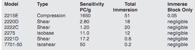
Table 3.1: Thermal transient response of several accelerometers.
In obtaining these data, the transducer and mounting block were stabilized at 82°F and then plunged into an ice bath at 32°F. The transient output following immersion was a series of two to five low-frequency polarity reversals of approximately sinusoidal shape within a time span of 1 to 10 seconds. The results are indicative of the maximum pyroelectric sensitivity of various transducers only under the described test conditions. Actual pyroelectric outputs for any particular accelerometer-amplifier combination should be experimentally determined under the temperature conditions present in the measurement.
A word of caution: Compression accelerometers (built with P-8 or P-10 crystals) which have been subjected to changing ambient temperatures while disconnected should not be connected to the amplifier without first shorting the transducer terminals. Damaging (not lethal, but shocking) potentials of several hundred volts have been observed in open-circuited accelerometers due to pyroelectricity.
Transverse Motion
For any single-axis accelerometer, one axis provides maximum response to an acceleration input. In an ideal accelerometer there would be no output signal for acceleration inputs along any other axes. In practice it is very difficult to produce this ideal transducer due to small manufacturing tolerances. However, a quality accelerometer will have minimal transverse sensitivity. Typical practical values are 3% or less in the axis of maximum transverse sensitivity.
Almost all Endevco accelerometers are tested for transverse sensitivity as a normal inspection step in their manufacture. The input motion must be unidirectional. Most electrodynamic vibration exciters do not have adequate low transverse motion to test high quality accelerometers. Because of this, Endevco developed a special mechanical, large displacement shaker which operates at 12 Hz and 7 g. Direction of motion is well-controlled, and the moving assembly permits rotating the accelerometer while it is being vibrated. Thus, the transverse sensitivity can be measured to produce a plot similar to FIG. 3.8 and the maximum transverse sensitivity noted on the ac celerometer calibration card. The value supplied is only a measure of the misalignment of the accelerometer. Further errors can be caused by improper surface preparation and mounting (flatness, smoothness, perpendicularity).
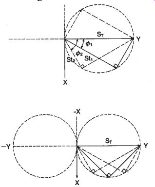
FIG. 3.8: Typical transverse sensitivity plot.
Electromagnetic Interference
Radio frequency and magnetic fields have no effect on piezoelectric elements. How ever, if an accelerometer includes magnetic materials, a spurious output may be observed when it is vibrated in a high magnetic field or subjected to high intensity changing magnetic flux. Adequate isolation must be provided against RF ground loops and stray signal pick-up. Insulated mounting studs can be used to electrically isolate accelerometers from ground. High intensity RF or magnetic fields may require special shielding of the accelerometer, cable, and amplifier.
Other types of accelerometers will have varying sensitivities to EMI/RFI environments depending on their construction, internal shielding, and connecting cables.
Some shock environments also include a high intensity electromagnetic pulse. Since this causes a rapidly changing magnetic field around the accelerometer, it can generate a high voltage pulse in the accelerometer and connecting cable. The induced voltage may exceed the shock signal, and may be high enough to damage signal conditioning electronics. Although it cannot prevent damage, a placebo sensor can sometimes be used to minimize the distortion of the acceleration data.
A placebo accelerometer is identical to the measurement accelerometer in all respects except it has zero sensitivity to acceleration. Therefore, any signal from the placebo must be noise induced by the environment. By placing the placebo near the measurement unit, it is exposed to the same environment. Thus the signal from the placebo can be subtracted from the signal from the measurement unit, and the result is the acceleration signal. This is not a foolproof technique, though, as some environmental effects may change the performance of the measurement unit without producing noise (change sensitivity, cause zero offset, etc.).
4. Applicable Standards
IEST Institute of Environmental Standards and Technology, 5005 Newport Drive, Suite 506, Rolling Meadows, IL 60008-3841, USA, 1-847-255-1561; www.iest.org; IEST RP-DTE011.1, 2003 ISA
ISA, The Instrumentation, Systems and Automation Society, 67 Alexander Drive, Research Triangle Park, NC 27709, USA, 1-919-990-9314; www.isa.org; ISA-RP37.2 1982, ISA-RP37.5-1975, ISA-Dtr37.14.01 (draft in process).
5. Interfacing Information
The fast rise time, high frequency content and high amplitude of most shock pulses requires special attention to the mounting of the accelerometer. Electrical connections and signal conditioning must be capable of accurately processing the transient signal without introducing extraneous noise.
Mechanical Interface, Mounting
For specimens having small cross-sectional dimensions, the attachment method, as well as the size and mass of the accelerometer, can alter the stiffness of the specimen.
Ideally, the dimensions of the accelerometer should be small compared to the dimensions of the structure in the local area where the accelerometer is attached. If the accelerometer dimensions are too large, the local stiffness of the structure increases and the resonance frequency and amplitude of vibration are correspondingly changed.
Similarly, the use of a fixture or accelerometer mounting stud may produce these stiffening effects. Choose microminiature accelerometers and use cement mounting for these small structures.
In addition to the accelerometer's effect on the dynamics of the mechanical system, an error source can also be introduced if the accelerometer is not securely attached to the structure. As frequency content increases, one must take special steps to attach the accelerometer. Accelerometers that are designed for stud mounting will ideally be mounted using the provided mounting stud and properly torquing them into the specified tapped hole.
Accelerometers may be cemented directly to the test surface with several types of epoxies and quick-set cements. The strength of the bond should be evaluated, particularly if severe shock amplitudes are expected. If strains may be present on the surface, cements should be chosen with appropriate elastic properties. To avoid degradation, bonds must be thin, for example, 0.1 mm or thinner. Cyanoacrylate adhesives provide extremely thin bonds and minimal response change with miniature designs.
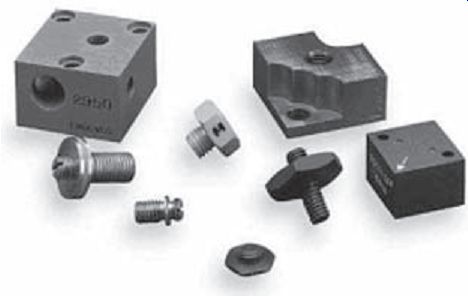
FIG. 5.1: An assortment of special mounting blocks and adapters.
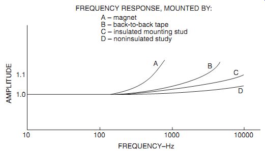
FIG. 5.2: Effect of attachment means on frequency response of a 30-gram
accelerometer.
Threaded studs are used to mount most accelerometers. Several important considerations are:
1. The surface condition of both the accelerometer and test specimen must be flat, smooth and clean. For most applications, the surface should approximate a 0.0003 inch TIR flatness and less than 32 micro-inch rms roughness.
2. Coating all mating surfaces with a thin film of oil or acoustic couplant improves coupling at high frequencies and is recommended when frequency components exceed 2000 Hz.
3. The manufacturer's recommendations for mounting torque should always be followed.
4. Insulated mounting studs may be needed for electrical isolation in some applications. When used, the resonant frequency is reduced and the effect on frequency response can be significant. For example, the resonant frequency of a 30 kHz, 1-ounce accelerometer typically reduces to 25-26 kHz when an insulated stud is used. Below 5 kHz the difference is less than 1%.
5. If the accelerometer cannot be mounted to a rigid block or boss, an accelerometer with low base strain sensitivity should be used.
The use of mounting blocks and fixtures almost always degrades frequency response above 1000-2000 Hz for all but the microminiature accelerometers. When tests are performed at higher frequencies, a frequency response calibration of the accelerometer with fixturing is recommended. If biaxial or triaxial measurements are required, biaxial or triaxial accelerometers provide better frequency response than uniaxial accelerometers on a fixture or block. FIG. 5.2 shows typical deviations in frequency response for a 30-gram accelerometer having a 30-kHz resonance frequency when mounted by different techniques.
Endevco Technical Paper Number 312, by James Mathews, explores the effect of various mounting methods on lighter weight accelerometers at different temperatures.
Generally, the best adhesive is a cyanoacrylate such as Aron Alpha, or Super Glue.
They cure very quickly at room temperature, and provide a broad frequency range and good temperature range. Disadvantages are the need for a solvent to break down the glue bond for removal, time-consuming removal, and difficulty getting a good bond on a rough surface.
Dental cement is also useful in many applications. It provides good transmissibility and high strength. However, like the cyanoacrylates, it is difficult to remove from the test structure and from the accelerometer.
Not Recommended for shock measurement:
Waxes, such as petro-wax and beeswax, double-sided tape, hot glue and magnetic mounts are not recommended for accelerometer mounting for shock measurements.
Petro-wax is often a convenient alternative, but has rather strict limitations. It is very easy to use, but requires a thin (less than 0.1 in.) wax layer. It is also very quick to use and easy to remove. Because of limited bonding strength, Petro-wax should not be used at peak vibration levels above about 20 g, frequencies above 2 kHz, or temperatures above 200°F.
Double-sided tape is also quick and convenient, and has a temperature range similar to cyanoacrylates. However, it has low bonding strength limiting the amplitude range.
Cable motion of some top connector or high profile accelerometers can cause trans verse forces that may break the bond.
Hot glue from a glue gun may be useful, is better than waxes or tape, but is problematic for shock measurements. Hot glue mounting is appropriate for temperatures from -18°C to +93°C. Above 93°C, hot glue loses its stiffness and frequency response decreases rapidly. It is very convenient and provides quick cure time. The quick cure time is also one of its greatest disadvantages, requiring the user to mount the accelerometer as soon as the glue is applied. Maintaining a thin bond line for maximum transmissibility is difficult with hot glue applications.
Magnetic mounts are not recommended for shock measurement. For vibration measurements, if the mounting surface is a magnetic material, accelerometers are often mounted using a magnetic mounting attachment. They are often used on industrial machinery that has cast iron or steel structures. They offer ease of use, quick mounting, broad temperature range, good holding strength, and are available in a variety of sizes. Disadvantages are size and weight (may increase mass loading effects), reduced bandwidth and the need for careful application. If a user "slaps" the accelerometer/ magnet onto a hard surface, the high frequency, high amplitude shock can cause catastrophic damage to an accelerometer.
TIP: If possible, it is advisable to have the accelerometer calibrated for frequency response, at the expected usage level and temperature, mounted as it will be mounted in service. Ideally, shock measurement sensors should be calibrated using a shock input.
Electrical Interface, Signal Conditioning
Signal conditioning electronics must be properly matched to the accelerometer used.
Shock measurement may be accomplished by almost any type of sensor, so the user must be sure to match the signal conditioner to the type of sensor. Charge mode ("High Impedance") accelerometers require a charge amplifier; IEPE ("Low Impedance") accelerometers require a signal conditioner that provides constant current excitation and a coupling capacitor; strain gage (piezoresistive or metal strain gage) and variable capacitance accelerometers require a bridge amplifier (usually an "instrumentation amplifier") with excitation voltage source; velocity sensors require an instrumentation amplifier but do not need any excitation voltage source.
Regardless of the type of sensor, the signal conditioner must have adequate low- and high-frequency response and any filtering must be designed for transients.
6. Design Techniques and Tips, with Examples High Mechanical Resonance Frequency
Mechanical resonance of a shock sensor should be at least three times (five times is recommended) the highest frequency in the transient being measured. Frequency response at one-fifth of the resonance frequency, for most shock sensors, is up by about four percent; at one-third the resonance frequency, response will be up about 12%.
Rugged
High frequency or short rise time of the shock pulse may excite the resonance of the sensor, so the sensor should be able to withstand occasional resonance excitation without permanent damage. Even relatively low level excitation at frequencies near the resonance frequency can cause excessive response because of the high Q resonance of most shock sensors. Piezoresistive (silicon strain gage) accelerometers are often broken by this kind of excitation. Although piezoelectric accelerometers may survive resonance excitation, they may be damaged such that their sensitivity decreases. Repetitive resonance excitation of piezoelectric accelerometers may cause low cycle fatigue failure of the crystal or other internal components.
Damped Resonant Response
Some piezoresistive and variable capacitance accelerometer designs incorporate mechanical damping to flatten their frequency response curves and reduce the Q of their resonance responses. The ideal damping ratio is 0.707 times critical to provide mini mal phase distortion and ideal frequency response.
Mechanical Filtering
There are two shock accelerometer designs (Endevco 7255A and 7270AM6) that incorporate mechanical filtering between the mounting surface and the sensing mechanism. This provides mechanical low-pass filtering to protect the sensing mechanism and to flatten frequency response. It is combined with an integral matched electronic filter to provide flat response up to 10 kHz and then produce rapid rolloff at higher frequencies. External mechanical filter adapters have also been utilized in some special applications. FIG. 6.1 shows a mechanical schematic of an internal mechanical filter.
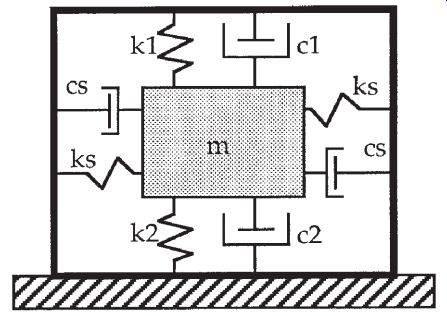
FIG. 6.1: Internal mechanical filter model.
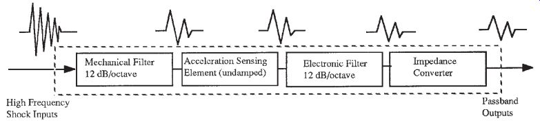
FIG. 6.2: Integral electronic filter schematic.
Electronic Filtering
Electronic low-pass filtering is often used in shock measurement systems. It can be incorporated into the sensor design, included in the signal conditioning, provided for anti-aliasing prior to an analog to digital converter, or performed with digital signal processing as part of the data post processing. In most cases, the earlier in the instrumentation chain the low-pass filtering is performed, the better the results and the less the likelihood of distortion, clipping, or overloading. FIG. 6.2 shows a schematic of an accelerometer with both mechanical and electronic filtering built in.
7. Latest and Future Developments
MEMS
Micro-Electro-Mechanical Systems (MEMS) are fabricated by chemically etching silicon or other similar materials to precisely controlled shapes. If a silicon wafer, sliced from a silicon crystal, is photolithographically masked and the proper etchant applied, geometrically precise shapes can be produced. Depending on the orientation of the wafer cut, the etchant, and the time of exposure, deep rectangular or other precise shapes can be etched into the silicon. This, combined with doping and thin film processes, can be used to produce very small, precisely controlled mechanical structures, which may also incorporate electronic components.
MEMS is used to fabricate small, lightweight, extremely robust silicon sensing elements that are used in some shock sensors.
References
1. Ed. Jon S. Wilson, Shock and Vibration Measurement Technology, Publ. Endevco (Part No. 29005), San Juan Capistrano, CA, 2002.
2. IEST RP DTE-011.1, Sensor Selection for Shock and Vibration Measurement, Publ. Institute of Environmental Sciences and Technology, Chicago, 2003.
3. IEST RP DTE-012.1, Handbook of Dynamic Data Acquisition and Analysis, Publ. Institute of Environmental Sciences and Technology, Chicago, 1993.
4. Anthony Chu, Endevco Technical Paper 290, Zeroshift of Piezoelectric Accelerometers in Pyroshock Measurements, Endevco, San Juan Capistrano, CA, 1987.
5. Anthony Chu, Endevco Technical paper 308, Built-In Mechanical Filter in a Shock Accelerometer, Endevco, San Juan Capistrano, CA.
6. James Mathews, Endevco Technical Paper 312, Guide to Adhesively Mounting Accelerometers, Endevco, San Juan Capistrano, CA, 1998.
NEXT: Test and Measurement Microphones
PREV: