AMAZON multi-meters discounts AMAZON oscilloscope discounts
1. Introduction
Noncontact sensors and measurement devices-those that monitor a target without physical contact-provide several advantages over contacting devices, including the ability to provide higher dynamic response to moving targets, higher measurement resolution, and the ability to measure small fragile parts. Noncontact sensors are also virtually free of hysteresis, the error that occurs with contacting devices at the point where the target changes direction. With these noncontacting sensors there is no risk of damaging a fragile part because of contact with the measurement probe, and parts can be measured in highly dynamic processes and environments as they are manufactured.
Noncontact sensors are based on various technologies including electric field, electromagnetic field, and light/laser. Two complementary sensor technologies will be discussed in detail in this section: capacitive--electric field based, and inductive (eddy current)--electromagnetic field based.
A capacitive or inductive sensor consists of a probe, which is the actual physical device that generates the sensing field, and a driver, the electronics that drive the probe and generate the resulting output voltage proportional to the measurement. In some sensors, the driver is physically integrated in the probe itself.
Capacitive and inductive noncontact sensors have many similar characteristics as well as some characteristics unique to each technology. In the following pages we will discuss those things which are common to each of the technologies, compare those things which are different, and look at applications for each and at the unique solutions that are possible when using them together. We will start with capacitive sensors.
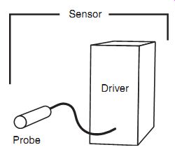
FIG. 1.1: Noncontact sensor system.
2. Capacitive Sensors
Capacitive sensors are noncontact devices used for precision measurement of a conductive target's position or a nonconductive material's thickness or density. When used with conductive targets they are not affected by changes in the target material; all conductors look the same to a capacitive sensor. Capacitive sensors sense the surface of the conductive target, so the thickness of the material is not an issue; even thin plating is a good target. Capacitive sensors are widely applied in the semiconductor, disk drive and precision manufacturing industries where accuracies and high frequency response are important factors. When sensing nonconductors they are popular in packaging and other industries to detect labels, monitor coating thickness, and sense paint, paper, and film thicknesses.
Capacitive displacement sensors are known for nanometer resolutions, frequency responses of 20 kHz and higher, and temperature stability. They typically have measurement ranges of 10 µm to 10 mm although in some applications much smaller or larger ranges can be achieved.
Capacitive sensors are sensitive to the material in the gap between the sensor and the target. For this reason, capacitive sensors will not function in a dirty environment of spraying fluids, dust, or metal chips. Generally the gap material is air. Capacitive technology also works well in a vacuum, but the sensors must be properly designed for the peculiarities of a vacuum environment to prevent the probes from compromising the vacuum. Under some circumstances they can be used while immersed in a fluid but this is not common.
When used with a conductive target, capacitive sensors are usually factory calibrated. Using capacitive sensors with nonconductive materials requires experimentation to determine the sensor's sensitivity to the material and the technology's suitability for the measurement.
Capacitive Technology Fundamentals
Capacitance is an electrical property that exists between any two conductors that are separated by a nonconductor. The simplest model of this is two metal plates with an air gap between them. When using capacitive sensors, the sensor is one of the metal plates and the target is the other. Capacitive sensors measure changes in the capacitance between the sensor and the target by creating an alternating electric field between the sensor and the target and monitoring changes in the electric field.
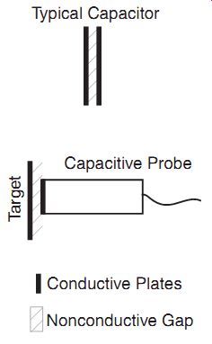
FIG. 2.1: A capacitor is formed by the target and the capacitive probe's
sensing surface.
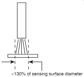
FIG. 2.2: "Spot size" on the target is about 30 percent
larger than the probe's sensing surface area.
Capacitance is affected by three things: the sizes of the probe and target surfaces, the distance between them, and the material that is in the gap. In the great majority of applications, the sizes of the sensor and target do not change. When used with conductive targets, the gap material does not change. The only remaining variable is the distance between the sensor and target, so the capacitance is an indicator of the gap size, or the position of the target. Capacitive sensors are calibrated to produce a certain output change to correspond to a certain change in the distance between sensor and target. This is called the sensitivity.
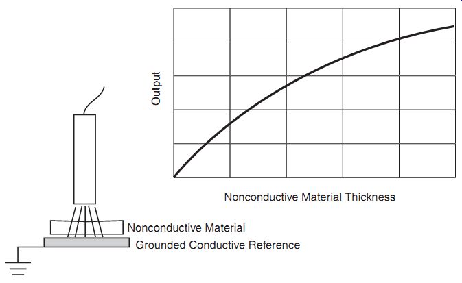
FIG. 2.3: When measuring nonconductors, the electric field from a
capacitive sensor passes through the nonconductive material on its way
to a conductive target.
Target Considerations
The electric field generated by a capacitive sensor typically covers an area on the target approximately 30 percent larger than the sensor area. Therefore, best results are obtained when the target is at least 30 percent larger than the sensing area of the probe. Sensors can be specially calibrated to smaller targets when the application demands it.
When used to measure nonconductive materials, the gap between the sensor and a conductive target is held constant and the material to be measured is passed through the gap. This way the gap is unchanging and the only remaining capacitance variable is the gap material. The output of the sensor will change with changes in the material's thickness, density, or composition. Holding two of these variables constant enables measurement of the third; for example, when a strip of plastic has a constant composition and density, changes in the capacitance can only indicate a change in thickness.
3. Inductive Sensors
Inductive sensors, also known as eddy current sensors, are noncontact devices used for precision measurement of a conductive target's position. Unlike capacitive sensors, inductive sensors are not affected by material in the probe/target gap so they are well adapted to hostile environments where oil, coolants, or other liquids may appear in the gap. Inductive sensors are sensitive to the type of target material.
Copper, steel, aluminum and others react differently to the sensor, so for optimum performance the sensor must be calibrated to the correct target material.
Inductive sensors are known for nano meter resolutions, frequency responses of 80 kHz and higher, and immunity to contaminants in the measurement area.
They typically have measurement ranges of 0.5mm to 15mm although in some applications much smaller and larger ranges can be achieved. Inductive sensors' tolerance of contaminants make them excellent choices for hostile environments or even for operating while immersed in liquid.
An inductive sensor's magnetic field creates electrical currents within the target material and therefore the targets have a minimum thickness requirement. Details are provided in the next section.
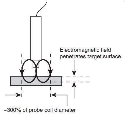
FIG. 3.1: Inductive sensors use electromagnetic fields.
Inductive Technology Fundamentals
While capacitive sensors use an electric field for sensing the surface of the target, inductive sensors use an electromagnetic field that penetrates into the target. By passing an alternating current through a coil in the end of the probe, inductive sensors generate an alternating electromagnetic field around the end of the probe. When this alternating field contacts the target, small electrical currents are induced in the target material (eddy currents). These electrical currents, then, generate their own electro magnetic fields. These small fields react with the probe's field in such a way that the driver electronics can measure them. The closer the probe is to the target, the more the eddy currents react with the probes field and the greater the driver's output.
Inductive sensors are affected by three things: the sizes of the probe coil and target, the distance between them, and the target material. For displacement measurements the sensor is calibrated for the target material and the probe size remains constant, leaving the target/probe gap as the only variable. Because of its sensitivity to material changes, eddy current technology is also used to detect flaws, cracks, weld seams, and holes in conductive materials.
Target Considerations
Inductive sensors are sensitive to different conductive target materials. Sensors must be calibrated to the specific material with which they will be used. Some materials behave similarly and others differ significantly. There are two basic types of target materials: ferrous (magnetic) and nonferrous (not magnetic). Some inductive sensors will work with both materials, while others will only work with one type or the other.
Some ferrous materials include iron, and most steels. Nonferrous materials include aluminum, copper, brass, zinc and others.
Inductive sensors are frequently used to monitor rotating targets such as crankshafts and driveshafts. However, measurements of rotating ferrous targets generate small errors because of tiny variations within the target material. This is called electrical runout or magnetic runout. These errors are quite small, on the order of 0.001 mm, which is negligible in the measurement of larger motions such as driveshafts. But inductive sensors are not well suited to high resolution measurement of rotating ferrous targets where they are expected to measure changes of 0.0001 mm.
Ideally, the target's measured surface must offer an area three times larger than the probe's diameter. This is because the electromagnetic field from an inductive sensor's probe is approximately three times the probe's diameter. Sensors can be specially calibrated to smaller targets when the application demands it.
Another target consideration is the thickness of the target material. Because electro magnetic fields penetrate the target, there is a minimum thickness requirement for the target. The minimum thickness is dependent on the electrical and magnetic properties of the material and on the frequency at which the probe is driven. As the frequency goes up, the minimum thickness goes down. This table lists some minimum thick nesses for common materials with a typical 1 MHz drive frequency.
Copper 0.2 mm
Aluminum 0.25 mm
304 Stainless Steel 0.4 mm
Brass 1.6 mm
1040 Steel 0.008 mm
416 Stainless 0.08 mm
Iron 0.6 mm
4. Capacitive and Inductive Sensor Types
Capacitive and inductive sensors are available in three basic types: proximity switch es, analog output, and linear output.
Proximity switches simply provide an on or off output to indicate whether or not the target is present in front of the probe. The distance from the probe to the target re quired to activate the proximity switch may be adjustable or may be fixed. Proximity switches do not provide any indication of the target's actual position, only whether or not its position is within the set proximity. Proximity sensors often have the driver electronics integrated in the probe body. They are inexpensive and readily available but they are not suited to precision positioning applications that require continuous readings of the target position.
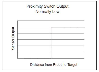
FIG. 4.1: Proximity type sensors only provide off or on outputs which
are triggered by the target position.
Analog output sensors provide a continuous analog output voltage that changes pro portionately to the changes in the probe/target gap. Common output ranges are 0 to 10 VDC, ±10 VDC, 0-20 mA, or 4-20 mA. With analog sensors, the relationship of the output to the changing gap is not linear. While the output is not linear, it is repeat able, allowing for the accurate detection of a repeated position of the target. Analog output sensors frequently have gain and offset adjustments for adjusting the sensor to each application. Adjustable setpoint outputs are often provided on this type of sensor.
These allow the user to set target position points at which digital outputs are activated.
[...]
5. Selecting and Specifying Capacitive and Inductive Sensors
Selecting the proper sensor starts by determining which of the three sensor types discussed previously is appropriate to the application. Proximity switches can be used to simply detect the presence of a target. Analog output sensors can be used for simple control of a process. Linear output sensors can be used for precision dimensional measurement of position, vibration, and motion.
Physical Configuration
Sensors are available in a large variety of shapes and sizes. The probes are usually cylindrical and are available with varied mounting schemes including threaded bodies for thru-hole or tapped hole mounting and smooth bodies for clamp mounting.
Cylindrical probes range in size from 3mm to over 50mm. Probes are also available in other shapes as well, such as rectangular or flat, coin-like disks. These probes provide a lower profile design for sensing in areas where the length of a cylindrical probe may be prohibitive.
The physical size of the probe is directly related to the measurement range and offset of the sensor. Larger probes have a larger range and offset. Capacitive and inductive sensors are readily available with measurement ranges from 10 µm to 15 mm. Some manufacturers are willing to create custom probe designs for individual applications.
These may be larger or smaller versions of standard probes or they may be incorporated into PCB designs or flex circuits for inclusion in equipment designs.
Drivers are available in various packages including: DIN rail mount, plug-in cards, bench top boxes, and small modules that are inline with the cable to the probe. Some drivers are integrated into the probe body itself, especially with the proximity switch type sensor.
Terminology
To make the best selection of sensor from the wide variety available you must first understand the terms used in the specifications. Unfortunately, not all manufacturers use precisely the same definitions but they are at least similar. These are some terms and definitions that you will encounter.
Output (or Output Range)
Output describes the type and range of the sensor's output which will be used to determine the measured dimension. Typical outputs are: 0-10 VDC, ±10 VDC, 4-20 mA, and 0-20 mA. The output indicates the total change of the output as the target moves through the total range. (Proximity switch sensors only have on/off switched outputs).
Range (or Measurement Range)
Range is simply the operating range of the sensor. Sometimes the sensor's range is plainly stated as a range such as 2 mm-3 mm. This indicates that the sensor can mea sure the position of the target when its distance from the face of the probe is between 2 mm and 3 mm. However, range is sometimes given as a single dimension such as 1mm. This means that the total range over which the sensor can measure the target is 1mm but it gives no information as to where this 1mm range is located in terms of absolute distance from the probe face. In this case another specification is given called offset or standoff.
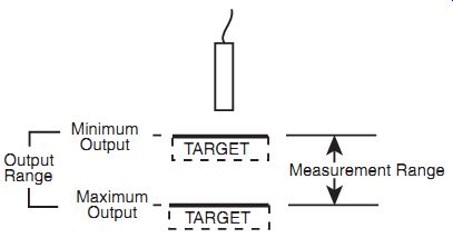
FIG. 5.1: How the "Output" and "Range" of a sensor
relate to target position.
Offset or Standoff
Offset or Standoff indicates where the active range is located relative to the probe's face. The range example above of 2 mm-3 mm may be listed as having a range of 1mm and an offset of 2 mm. This is typical for sensors with a single polarity output such as 0-10 VDC. Some manufacturers may take a bipolar approach and define this same sensor as hav ing a 2.5 mm standoff with a ±0.5 mm range. This is commonly used for sensors that have a bipolar output such as ±10 VDC.
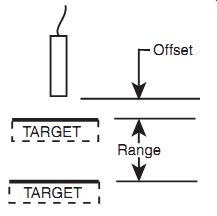
FIG. 5.2: Some ranges are defined with an "offset" value.
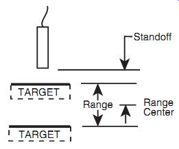
FIG. 5.3: Some ranges are defined with a "standoff" value.
Sensitivity
Sensitivity indicates how much the driver output changes as a result of a change in the gap between the target and the probe. If the sensitivity were 0.1 mm/1 V then for ev ery 0.1 mm of change in the gap, the output voltage will change 1 V. When the output voltage is plotted against the gap size, the slope of the line is the sensitivity.
Linearity
This specification applies only to linear output type sensors, although it may be given occasionally for analog output sensors. This is a measure of how straight the line is when the target position is plotted against the driver's output. It describes how far the actual output varies from a perfect straight line drawn through the points, typically using a least squares fit calculation. It is usually given as a percent of full scale.
Linearity is important for precise measurements throughout the active range of the sensor. Linearity is only a measure of the straightness of the sensor's output. It is a major contributor to the accuracy of the sensor but it is not equivalent to accuracy. A sensor may be very linear, but be very inaccurate due to gross sensitivity errors, but a nonlinear sensor's accuracy will always be limited by the nonlinearity.
Bandwidth (Frequency Response)
When measuring a vibrating target the output is frequency dependent. As the frequency of the vibration increases, at some frequency the output begins to decrease due to frequency limitations within the driver electronics. Bandwidth usually specifies the frequency at which the output falls to -3 dB-approximately 70 percent; for example, 1 mm of vibration at the bandwidth frequency would appear as 0.7 mm at the output.
Resolution
Resolution is defined as the smallest reliable measurement that a system can make. The resolution of a measurement system must be smaller than the smallest measurement the sensor will be required to make. The primary determining factor of resolution is electrical noise. Electrical noise appears in the output causing small instantaneous errors in the output. Even when the probe/target gap is perfectly constant, the output of the driver has some small but measurable amount of noise that would seem to indicate that the gap is changing. This noise is inherent in electronic components and can be minimized, but not eliminated.
To measure resolution the noise voltage from the driver is viewed on an oscilloscope and measured. That measurement is listed as the resolution of the sensor. But there are two ways to calculate the measurement of the noise. The first is peak-to-peak (p-p). This simply measures the difference from the highest point to the lowest point.
The other is RMS (root mean square) which is a mathematical calculation similar to but not the same as averaging. The RMS measurement of resolution is considerably lower than the p-p resolution. Both can be legitimate measurements, but be sure when comparing that all the sensors you are considering are using the same method.
Resolution is bandwidth dependent. Lower bandwidth means less electrical noise and therefore smaller resolution. Be careful when comparing resolutions that you know the bandwidth at which the measurement was taken. Many manufacturers list resolutions at several bandwidths, while others do not specify the bandwidth over which the resolution specification applies, resulting in an ambiguous specification.
Thermal Errors
All things electronic have the possibility of changing with temperature. In addition to electronic drift, physical changes in probes due to expansion and contraction can create output change that is related to temperature. Many of today's sensors are well designed to minimize and/or compensate for thermal errors but they are always present to some extent. Specifications may include thermal information listed as temperature coefficient or thermal drift. These specifications normally indicate the amount of change in the output per degree of temperature change.
Accuracy
Accuracy is the final result of the accumulated error sources that exist in any measurement system. Some error sources are part of the sensor itself, such as linearity, sensitivity errors, and thermal drift. Other sources are part of the measurement system as a whole, including fixturing, ambient temperature changes inducing differential thermal expansion within the system, mechanical alignment, electrical noise sources, and the accuracy of the equipment interpreting the sensor output. Because accuracy includes many factors outside of the sensor itself, it is rare for sensor specifications to include accuracy.
6. Comparing Capacitive and Inductive Sensors
Capacitive and inductive sensors each have unique characteristics. Below is a comparison of typical parameters for standard sensors. This is intended to provide a general idea of how the technologies differ. This data is by no means exhaustive; sensors are available with parameters exceeding those listed in Table 8.6.1.
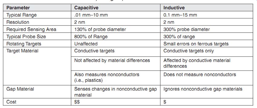
Table 6.1: Comparing capacitive and inductive sensors.
7. Applications
A myriad of applications exist for these sensor technologies. Some of these applications can use either technology equally well, while others require one technology over the other.
Typical Sensor Operation
Noncontact sensors generally indicate a change from a known state. They are not frequently used for absolute measurements. The probes are mounted to make the measurement and the output is adjusted to some reference, usually zero, while the sensor is measuring the current state of the part. Measurement then proceeds with changes in the sensor output indicating changes from this initial condition.
Linear or Analog
Whether an analog sensor or linear sensor is necessary will depend on the required accuracies and specifications of the application. Generally, where the application is intended to produce a specific dimensional measurement of a particular feature or parameter, linear is the best option. When the application can operate with a simple "more or less" type of measurement, an analog type sensor is sufficient.
Interpreting the Output
Converting the output of the sensor into dimensional units is accomplished with this simple formula:
Dimension = Output × Sensitivity
When using linear sensors the calculation is straightforward. A linear sensor's sensitivity is listed in calibration certificates or is otherwise listed on the sensor.
Multiplying the change in the sensor output by the sensitivity yields the dimensional change; for example:
(2 V) × (1 mm/1 V) = 2 mm
When using nonlinear sensors the sensitivity is not consistent throughout the range.
The average sensitivity can be determined experimentally by measuring two part masters of known dimension, recording the sensor output for each part master and calculating the sensitivity:
Sensitivity = (Change in Dimension)/(Change in Output)
Because of the nonlinearity there will be measurement errors for parts that have a different dimension than the masters.
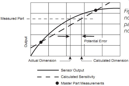
FIG. 7.1: Calibrating a nonlinear sensor with two part masters creates
errors at nonmastered points.
For more precise measurements with nonlinear sensors, an array of master parts is measured and recorded. The sensitivity is calculated for each sequential pair of parts.
The sensitivity will be different for each pair. These test measurements can be used to calculate accurate measurements with a computer program. The program can simply determine which sensitivity applies to the measured part, or, for maxi mum accuracy, a polynomial can be constructed based on the test measurements.
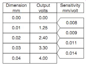
FIG. 7.2: Using multiple masters to calculate different sensitivities
throughout the range of a nonlinear sensor.
Multiple Channel Systems
Multiple channel measurements of the same physical target usually require that the sensors' drive oscillators be synchronized in frequency and phase. Sensor systems for multiple channel measurements need to be specified as such when ordered from the manufacturer so they are configured and calibrated to work together. Some less demanding applications may work with two independent, off-the-shelf sensors, but precision measurements will require synchronized sensors.
Applications for Capacitive or Inductive Sensors
These are typical applications in which either technology is effective assuming the measurement is taken in a relatively clean environment. Change the environment to include liquid, coolant, lubricant or other foreign material in the measurement gap and these all become applications for inductive sensors only.
All of the applications in this section assume a conductive target.
Relative Position (Displacement)
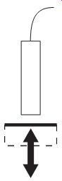
FIG. 7.3: Measuring target position; the most fundamental application
of noncontact sensors.

FIG. 7.4: Detecting a position window using a single sensor with two
setpoint outputs or two proximity type sensors.
This is the most typical application for displacement sensors. This measurement is used in servo systems, part inspection, photolithography stages, and a host of other applications ranging from nanometers to millimeters.
The probe is mounted to monitor the position of the target.
Changes in the output of the sensor indicate changes in position of the target. When using linear sensors, the output change of the sensor is multiplied by the sensitivity of the sensor to produce a dimensional value. Some sensing systems are available with integral displays that convert the sensor output and display the dimensional value.
This is a very specific application in which the position must be above a certain point but below another. This type of application is usually performed with an analog type sensor with two or more setpoints.
The probe is placed in the process to sense the position of the target.
A calibration routine follows in which each setpoint is adjusted to activate as a test or master target reaches the setpoint positions.
When setpoint 1 is active and setpoint 2 is inactive, the part is in the desired window.
If the setpoint outputs are in any other condition the part is no longer in the acceptable window and the system takes appropriate action.
This same application can be accomplished by using two proximity type sensors.
The outputs of the proximity sensors would be evaluated in the same way as the two setpoint outputs of the analog sensor. Cost, performance, and probe space determine the best solution. If there is room for two probes and the application doesn't require the higher performance and adjustability of analog sensors, proximity switches may be a more economical solution. Analog sensors are the choice if flexibility and adjust ability drive the application.
Deflection, Deformation, Distortion
Applied essentially as a multichannel displacement measurement, this application specifically measures the intentional or unintentional distortion of an object.
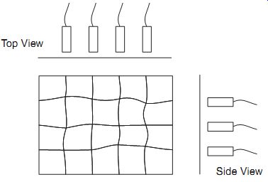
FIG. 7.5: Measuring deformation of a surface with an array of sensors.
Several probes are mounted to measure the positions of different areas of the part. As distortion occurs, the position change for each channel can be collected. This data can be interpreted directly by the user, or can be fed to computer software to analyze and report on the distortion and predict the end effect of the distortion on the process being monitored.
Thermal Expansion
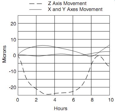
FIG. 7.6: Capacitive and inductive sensors monitor thermal expansion
in precision machine tools; here indicating 25 µm growth in the Z axis.
Thermal expansion and contraction can have profound effects on precision processes.
For example, high-performance machine tools (mills, lathes, etc.) suffer from thermal expansion of the spindle and the machine as a whole. This is from machine generated heat and, to a lesser extent, ambient temperature changes.
There are a few approaches to solving thermal expansion problems: (1) measure the expansion throughout the temperature range and compensate during production based on the current temperature, (2) in the case of machine generated heat, measure the expansion over time and determine the amount of time required for the process to thermally stabilize and include an appropriate warm-up time, (3) if possible, use a sensor to monitor the expansion during production and compensate in real time.
Thickness
There are two ways to measure thickness with sensors. The first is a basic single channel position measurement of the top surface of the target while it rests on a reference surface. Surface finish, contaminants, and other factors affecting the way the target rests on the reference surface will create errors in the thickness measurement.
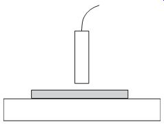
FIG. 7.7a: A simple one channel thickness measurement depends on the
quality of the contact between the target and the surface plate.
More precise thickness measurements which do not depend on a reference surface are accomplished with a two channel measurement. One channel measures the position of the top surface while the other measures the position of the bottom surface. The sum of the two indicate any changes in thickness while canceling any errors caused by the target moving up or down between the sensors.
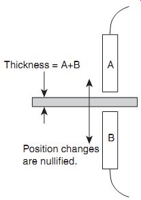
FIG. 7.7b: A two-channel, differential thickness measurement nullifies
errors created by changes in the target position.
As mentioned earlier in this section, inductive sensors require a minimum target thickness. Thin targets such as foils may not be thick enough for inductive sensors.
This is dependent on the specific material and inductive sensor.
Assembly Inspection Many assemblies include conductive and nonconductive parts. For critical assemblies 100 percent inspection is required to assure that the assembly includes the metallic component, which may or may not be visible.
Mount a probe such that the part to be inspected passes the probe such that the metallic part passes within the sensor's range.
Adjust the setpoint or a proximity switch to activate only when the metal is present.
Proximity type sensors can work in this application (especially inductive) but may not provide the level of adjustability required.
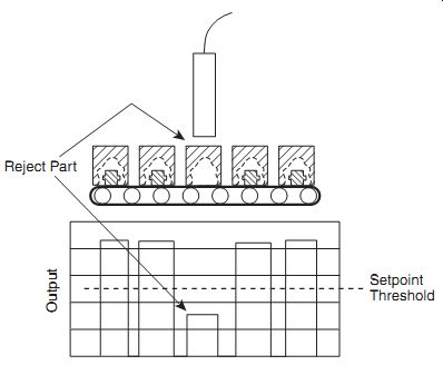
FIG. 7.8: Incomplete assemblies are detected on a production line
by a sensor with a switched output.
Vibration
Vibration is just a position measurement over time, but the output of the sensor is not only analyzed for position data but also for time-based information about the motion of the target. The sensor output is either viewed on an oscilloscope or collected by a computer data acquisition system for mathematical analysis.
Some manufacturers have basic signal processing modules designed to work with their sensors. These modules include peak capture functionality which can provide a TIR (total indicator reading) output. TIR is the difference between the maximum and minimum excursions of the output. A TIR output will indicate the total magnitude of the vibration of the target, but it provides no information on the time-based nature of the vibration.
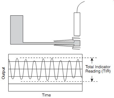
FIG. 7.9: Vibration can be monitored over time for detailed analysis
of simple TIR measurements.
When measuring vibration, bandwidth (frequency response) is a critical consideration in selecting a sensor. If the measurement is only concerned with total magnitude of the vibration, bandwidth must be only slightly higher than the highest expected vibration frequency. If the measurement is to analyze detailed time-based behavior of the vibration, a bandwidth from three to ten times higher than the highest vibration frequency is required.
Applications for Capacitive Sensors
Precision Spindle Error Motion (Runout)
Precision spindles in disk drives and high-performance machine tools are achieving error motions of less than 100 nanometers. The error motion in disk drive spindles is directly related to the amount of information that can be packed on a disk. The error motion in a machine tool is directly related to hole roundness, feature location, and the quality of surface finish. The only way to properly measure the error motion of these spindles is when they are at full speed. This is a perfect application for capacitive sensing technology because of inductive sensors' rotating target errors (electrical runout) when measuring ferrous targets.
In the machine tool application, a precision master is mounted in the tool holder of the spindle to function as the target. In the disk drive application the disk spindle itself is the target.
Two probes each are mounted in the X and Y plane (90° apart).
While the spindle rotates at operational speeds the outputs of the two channels are viewed on an oscilloscope or analyzed by computer software. When using an oscilloscope, the X channel is used to drive the horizontal axis and the Y channel is used to drive the vertical axis. This creates a lissajous pattern. The size and shape of the pattern gives indication of the amount and nature of the error motion of the spindle.
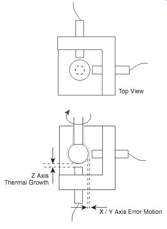
FIG. 7.10: Error motions of high precision spindles are measured by
capacitive probes in all three axes.
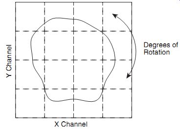
FIG. 7.11: Driving the horizontal and vertical axes of an oscilloscope
with the X and Y outputs indicates the motions of the rotating target.
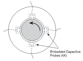
FIG. 7.12: Embedded capacitive probes monitor rotor motion in air
bearings and magnetic bearings.
For detailed analysis, computer software is required to calculate measurements for synchronous error motion (runout) and asynchronous error motion (nonrepeating runout NRR).
When precision rotating measurements of ferrous materials is required in a dirty environment, inductive sensors can be used by placing a nonferrous sleeve around the target or by characterizing the electrical runout of the target and using computer software to remove it from the result.
Rotor to Stator Gap (Embedded Sensors)
Stator to rotor gap can be a critical dimension in precision rotating devices such as air bearings and magnetic bearings. Capacitive probes can be designed to be embedded in the wall of the stators and monitor the position of the rotor. The sensor outputs are used as inputs to the servo system controlling the magnetic field or air pressure.
The specially designed probes are embedded by the bearing manufacturer and are in place for the final boring process of the stator. After final machining, the stator face with embedded sensors is as smooth as a standard stator. When the bearing is installed in the system, cables from the probes are connected to the driver electronics and the driver outputs connected to the system's servo inputs. When used in machine tools, these sensors provide extremely sensitive force measurements during the machining process.
Nonconductive Material Thickness
Because capacitive sensors are sensitive to gap material they are effective at measuring nonconductive targets. Assuming that the composition and density of a nonconductive material are constant, changes in thickness can be measured by capacitive sensors.
The electric field from the sensing area of a capacitive probe must eventually return to ground. Nonconductors by definition cannot provide a ground. Nonconductive measurement is usually performed while the target material is between the probe and a grounded reference as shown in FIG. 7.13. The gap between the probe and the grounded reference must be kept constant. Any change in that gap will appear as changes in the thickness of the target material.
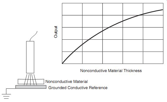
FIG. 7.13: A nonconductive target can be measured against a conductive
surface but the conductive surface must remain stationary.
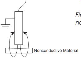
FIG. 7.14: Using a fringe field to sense a non-conductor without a
conductive backplate.
In some less critical applications, measurements of nonconductive targets can be made without the grounded reference target. In this instance, the electric field from the probe wraps back to the grounded outside shell of the probe or the fixturing that is holding it.
[...]
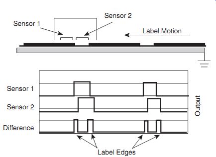
FIG. 7.16: Differential capacitive measurement senses the gap between
labels on a web.
Label Sensing
The current state of the art in label sensing employs capacitive technology. During the process of placing labels on containers such as bottles, the location of the leading edge of the label is critical to locating the label in the center of the bottle. Optical sensors were used to perform this function. Then in the 1990s, clear labels on clear backing became common and optical sensors were no longer functional. Because capacitive sensing only senses changes in density or thickness, and is not affected by color, it is an ideal solution.
In label sensors, the detection of the label edge is accomplished using a differential sensor. The sensor actually has two sensing areas that are driven by the same circuit. The sensor only activates its output when there is a difference between the two sensors. (This particular configuration and application is covered under a U.S. Patent.)
The advantage to the differential configuration is that the sensor is much more immune to changes in the gap between the sensor and the grounded reference. Any changes in the gap size are common to both sensors so there is no difference between them and the change does not affect the output.
Glue or Paper Additive Sensing
The presence and/or amount of glue or other material deposited on a nonconductive material has been solved in many industries using capacitive technology. If the thickness/density of the underlying material is constant, changes in the amount of glue or other material is easily detected with capacitive sensors.
The probe is mounted in a position such that the applied material passes through its sensing area. Tests are performed to determine the sensor's sensitivity to the mate rial and gain adjustments are made to an appropriate level. The output of the sensor is then monitored by the control system and either warns an operator if the material is no longer present, or in more sophisticated systems, the output is used to control the flow of the applied material.
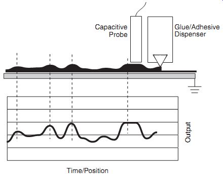
FIG. 7.17: Capacitive sensors' sensitivity to varying amounts of nonconductive
material make them ideal glue, adhesive, or additive sensors.
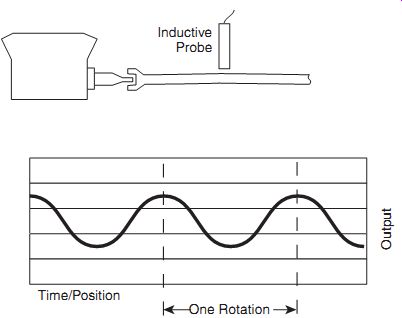
FIG. 7.18: Inductive sensors are ideal for measuring rotating motion
when the environment is dirty and accuracy less than a micron is not required.
Applications for Inductive Sensors Only These applications require a sensor that can operate in a dirty, hostile environment that would render a capacitive sensor ineffective or that exploit the unique nature of an electromagnetic field as opposed to an electric field.
Driveshaft Runout/Motion
While inductive sensors have small errors when measuring rotating, ferrous targets, these errors are usually less than a micron. There are many rotating target applications that take place in a dirty environment for which inductive sensors are well suited that do not require that level of resolution.
These measurements may be performed as part of a testing process or permanently installed in the final product. Examples are driveshafts or crankshafts running in an oil bath, or marine propeller driveshafts which may have water spraying or splashing in the sensing area, or power generator shafts which are monitored during operation to indicate bearing wear. The output of the sensor may be monitored by an operator or a computerized control system.
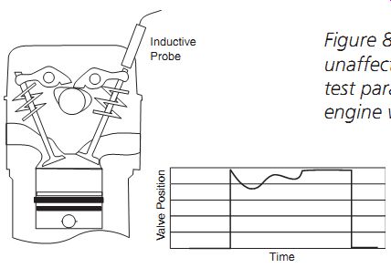
FIG. 7.19: Inductive sensors are unaffected by oil and can be used
to test parameters of internal combustion engine while they are in operation.
Valve Stroke, Piston Dynamics
Tests on internal combustion engines while they are running are ideal for inductive sensors. Their immunity to oil allows them to be installed directly in an engine for test during operation. One such test measures the position of the valve stem at its highest point. The probe is installed in the engine and positioned to sense the position of the end of the valve stem at its highest point. Measurements are taken while the engine is running and indicate the position of the valve stem as well as the repeatability of the valve stem position on consecutive excursions.
Calender Roller Gap
Rolling of sheets, coils, bars, and shapes is a process used to fabricate metals to proper thickness, shape, and texture. This rolling process also controls thickness, perforation, and texture on paper products, rubber, plastics, drywall, engineered wood, and other materials.
The calendar rolling process squeezes the material to shape and thickness through the bite area between two parallel calender rollers, which can be up to three feet in diameter and ten or more feet long. Depending upon material characteristics and process requirements, the material might be pre-heated or process working fluids could be present such as steam and solvents.
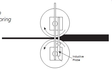
FIG. 7.20: Inductive probes help control material thickness by monitoring
the gap between calender rollers.
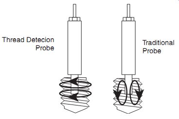
FIG. 7.21: Inductive sensors can detect the presence or quality of threads in a tapped hole.
The process requires precise control of roller gap to control quality and prevent roller crash damage and premature wear.
Inductive position sensors can measure the roller gap accurately in the hostile process environment while the material is running. This enables precision machine setup, real time roller gap control, and SPC data on the setup and running gap for all material produced.
Thread Detection
Inductive sensors are a perfect technology for detecting the presence/absence or the quality of threads in tapped holes. A traditional probe design in which the electromagnetic field radiates from the end of the probe can function as a thread sensor, but sensitivity is increased with specially designed thread detection probes. These probes have internal coils turned 90° so that the field emanates from the side of the probe's cylindrical body.
This gives deeper penetration of the field into the tapped surface. In its simplest application, these are used in automated production lines to check presence/absence of thread to check for a broken tap; especially when 0ppm defects are the requirement. A more sophisticated application uses the probes to monitor thread quality and depth to indicate the need to replace a worn tap. Thread detection probes are also monitored during insertion to detect a broken tap still present in the hole. The automation system stops the insertion if a broken tap is detected, thereby preventing damage to the probe.
Stamping/Molding Die Protection
When parts are formed through a stamping or molding process, offline measurement of finished product may not be desirable, since a significant quantity of product could be manufactured before a defect would be discovered.
Using inductive sensors during the forming process, real-time measurements can be made on part dimensions, die-half position/movement, mold closure, and mold core movement. Inductive sensors are the only choice because a stamping process will produce significant shock, often in an oily environment; the molding process can impart high temperatures (200°C) and significant pressures (20,000 psi) on the sensor.
In addition, these systems can be used to measure critical machine setup dimensions such as die closure position and the gap between the mold and core to ensure proper setup.
Application Using Capacitive and Inductive Sensors Together
This is a unique application that exploits the differences of the two technologies Film/Paint Thickness of Conductive Part For years measuring the thickness of paint or film against a moving metal substrate in a noncontact fashion has presented a difficult challenge. By using the unique aspects of capacitive and inductive sensors together, this can now be accomplished.
Capacitive sensors can measure the nonconductive paint or film, but they are also affected by any changes in the gap distance to the moving substrate. When the substrate is moving, it is not possible to discern if changes in the output are due to changes in the thickness of the paint or film or movement of the substrate.
Inductive sensors can measure movement of the substrate but they do not sense any changes in the paint or film thickness. (See FIG. 7.23.) If both technologies are used and their outputs combined differentially, any movement of substrate is cancelled through the differential operation, leaving only the changes due to thickness of the film or paint.
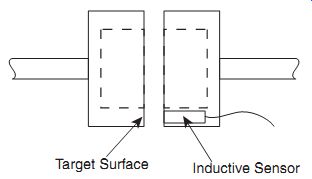
FIG. 7.22: Inductive sensors monitor injection molds for proper closure.
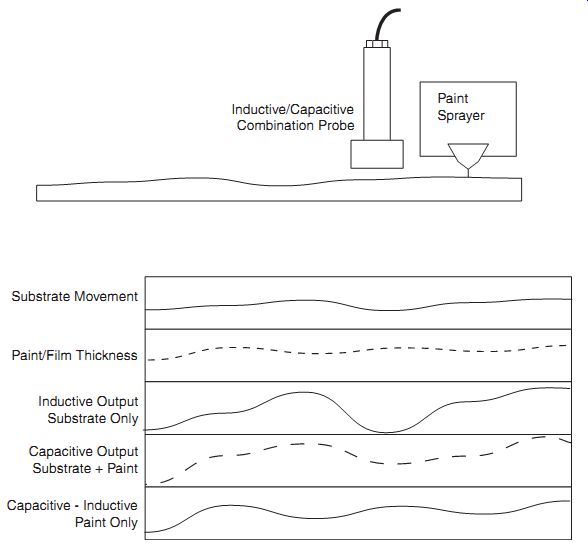
FIG. 7.23: Combining inductive and capacitive technologies in one
application to measure film or paint thickness on a metal substrate
Thickness Change = Capacitive Output - Inductive Output
which is essentially:
Thickness Change = (Substrate Movement + Thickness Change) - (Substrate Movement)
For greatest accuracy, the application should be performed with a specially designed probe that contains both capacitive and inductive sensing elements that are constructed to be coaxial. Coaxial construction assures that both sensors are reading precisely the same area of the target. If independent sensors are used, differences in the displacement of the substrate at the two different locations will appear as changes in the thickness of the film or paint. Don't underestimate this potential error source. When using sensors with sub-micron sensitivities, small differences can have profound effects.
Inductive Sensing Coil Capacitive Sensing Surface
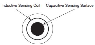
FIG. 7.24: End view
of a combination probe with capacitive and inductive elements.
Considerations for Maximum Effectiveness
Temperature effects are usually the largest source of error in a precision measurement.
Capacitive and inductive sensors exhibit some finite amount of drift associated with temperature. But with current design strategies these effects are minimized to very small amounts in comparison with temperature effects on fixturing and the physical properties of the target.
During design of the measurement system, care should be taken to minimize the structural loop-the total distance from the probe mount to the point of the measurement. The larger this loop, the more susceptible it is to temperature variations. There is also the potential for vibration. If not carefully designed, the probe mount system can function as a large tuning fork and vibrate at a resonant frequency. Stiffness of the mount is a key to minimizing these error sources.
Structural Loop
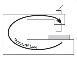
FIG. 7.25: Larger structural loops are sensitive to vibration and
thermal expansion. Keep them as small as possible.
Obviously, the best way to deal with temperature-related errors is to perform the measurement in a temperature stable environment.
8. Latest Developments
The physics of capacitive and inductive sensing has long been understood, not leaving much room for radical improvement in the physical design of probes. The relation ship between the area of the sensor and its measurement range will remain essentially unchanged. Electronics, however, continues to advance at a tremendous pace. One advancement is in reducing the electrical noise inherent in electronic amplifiers. This has resulted in increasing resolutions, which can now be measured in nanometers for high-end systems.
Another advancement has occurred in miniaturization. As circuitry gets smaller, more and more sensors will be produced with the electronics contained in the actual probe body. That style of sensor can't offer as much adjustability, so external electronics with adjustment knobs and switches are still the order of the day for applications requiring user setup and adjustment. But with miniaturization of computer technology, probes with embedded electronics will become available in which the adjustments are made through a simple serial interface to internal, electronic adjustments instead of external, physical adjustments. Obviously, these sensors would need to be connected to an external computer or controller that can transmit the setup commands to the sensor.
9. Conclusion
Capacitive and inductive sensors have been solving measurement problems for several decades. With each new decade and advancement of technologies such as automation, the demand and opportunities for these sensors continues to increase. Every year capacitive and/or inductive sensing solutions are discovered for problems that have nagged engineers for years. Increasing awareness of these sensing technologies will lead to better solutions sooner and provide an abundant saving of resources.
Resources
1. Capacitive Sensing Theory Website hosted by Lion Precision www.lionprecision.com/theory
2. Lion Precision Capacitance Displacement Measurement for 2003 Includes eleven page tutorial on capacitive sensing theory. Available from: Lion Precision 563 Shoreview Park Road St. Paul, MN 55126 USA 651-484-6544 www.lionprecision.com
NEXT: Electromagnetism in Sensing
PREV: