AMAZON multi-meters discounts AMAZON oscilloscope discounts
1. Introduction
This section discusses the basic principles behind the use of electromagnetism in sensing. Since many established sensor types rely on electromagnetism, it covers a broad set of designs and reviews several product types.
2. Electromagnetism and Inductance
Before we get too far into electromagnetism, we begin with a review of the properties of an inductor as used in electronic circuits. An inductor is a passive circuit element that resists changes in current. The equation governing its behavior is:
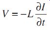
...where L is the inductance in units of henrys. As we can see from this equation, there is a voltage across the inductor whenever the current changes. The minus sign indicates that the voltage (V) opposes the change in current (I)--which is to say that whenever an external circuit tries to cause more current to flow, it must provide a volt age in order to overcome the voltage that arises in the inductor.
If we assume (as for all of the differential equations in this section) that the current and voltage are both oscillating quantities:
...then we have...
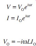
If we recognize Ohm's Law here (V = IR), then the effective resistance of the inductor is "R" = -(i ohm L). As was the case for a capacitor ("R" = 1/(i ohm C)), the i implies that there is a shift in phase between voltage and current, and the ohm (Greek omega) implies that the effective resistance increases with frequency.
Using this analogy, we can easily see how to build a large array of inductance-measuring circuits, which are exactly like resistance-measuring circuits (dividers and bridges). In fact, the most common approach to inductance measurement is a bridge.
How big is a typical inductance? The inductance of a coil is given by:
Assume we have a coil with a 1-cm diameter and a 1-cm length, with 1000 loops of wire. Then,
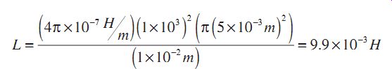
Now, if we want to measure the effective resistance of this device, we will need to apply an oscillating voltage at some frequency. Normally, if we used a frequency of 1 kHz, the effective resistance of this device would only be about 60 ohms. Clearly, this is a small resistance, and measuring it to a high degree of accuracy will be difficult. We may go to a higher frequency to improve this situation.
What is really preferred is an inductor with a higher inductance. This is achieved in a way that is very much like what is done in capacitors. In an inductor, we can fill the coil with a material that has a higher magnetic permittivity. For example, iron has a relative permittivity of about 300, and permalloy has a relative permittivity of as much as 5000. So, we generally see coils filled with metallic materials such as iron.
To understand the situation with coils, we must review some electromagnetic theory.
We will look at a few "laws" of electromagnetism and some example discussions of their effects.
Oersted discovered that whenever electrical charges move (current), a magnetic field is created. For the simple case of a straight wire, there is a magnetic field around the wire given by:
Since the magnetic field is a vector, we need also to be concerned about the direction.
For this case, the field lines form a loop around the wire, and the direction in the loop is determined by the righthand rule.
For a current of 1 ampere, the magnetic field 1 cm away from the wire is
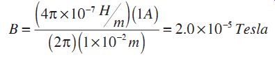
The earth's magnetic field is generally about 5 × 10^-5 Tesla, so this field is smaller than the earth's field. As we can see, the fields around wires are not generally large enough to be noticeable.
Whenever charges move in magnetic fields, there are forces on those charges. The expression for this force (known as the Lorentz force) is:
F = qV × B
Since V, B, and F are vectors, we need to recognize this as a vector cross-product, and use a different righthand rule to determine the direction of the resulting force.
In this case, the force is always perpendicular to the velocity, and causes a freely moving electron to be deflected into a circular orbit. Since the force and velocity are perpendicular, the speed of the electron is unchanged.
Finally, Faraday's law of induction states that whenever the magnetic field that passes through a loop of wire is changed, there will be a voltage induced in the coil. We define the flux, f (phi), as the product of the area of the loop and the component of the magnetic field perpendicular to the surface of the loop.
The induced voltage is therefore:
We can put all of this together to see what is going behind the concept of inductance. If we have a simple coil, and try to suddenly cause a current to flow through it, the initial current flow causes a magnetic field to begin to form in the coil. Since this magnetic field is increasing, there is a change in the flux through the coil, and an op posing voltage appears. Eventually, the current rises to its limiting value, the magnetic field is stable, and the opposing voltage dies away.
Throughout all of these equations, there are many minus signs to keep track of. Rather than become accurate bookkeepers, it is easier to become familiar with Lenz's Law, which simply states that the combined effect of all of these interactions is to resist the modification of the magnetic field. In the case of an inductor, the electromagnetic interactions resist current changes as a way to resist any change of the magnetic field in the coil. We shall see this effect in all inductance-based sensors.
3. Sensor Applications
A good example of the Faraday law of induction is illustrated in FIG. 3.1. Here a loop of wire is positioned between the pole faces of a permanent magnet. The mag netic field is confined to the region between the pole faces, and is essentially zero elsewhere. Therefore, the magnetic flux through the loops in this situation is simply the area of the loop that is within the magnetic field multiplied by the value of the field.
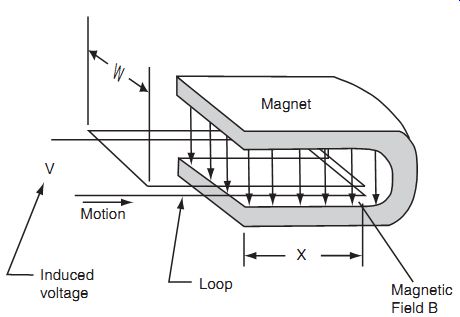
FIG. 3.1: Magnetic sensor.
A voltage V is induced in the loop whenever it moves laterally. In this case, we assume it is confined to motion left and right in the figure, and that the flux at any mo ment is given by:
Phi = Bwx
...where w is the width of the loop, x is the length of the loop within the coil, and B is the field in the magnet. Therefore, the voltage is:
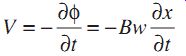
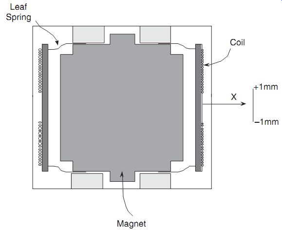
FIG. 3.2: Geophone.
Since dx/dt is really the velocity of the coil, we see that this configuration is useful as a motion detector, and useless as a position detector. This approach is the basis of many so-called "moving coil" detectors, in which a voltage is generated when ever an external signal causes a coil to move relative to a permanent magnet. A good example of a commercial product based on such a device is the Geophone, as made by GeoSpace Corp (see FIG. 3.2). In this device, a set of coils measures a differential voltage whenever a spring-supported magnet moves. This device is generally constructed with a fairly low frequency resonance--about 1 Hz. It is commonly used for detection of seismic signals or other low-frequency ground vibrations. It is also commonly used in the oil exploration business with buried explosive charges to map underground resource deposits.
Another very common approach to the use of electromagnetics in sensors is the inductive proximity sensor shown in FIG. 3.3. Here, a pair of coils are wired in a bridge circuit and biased with an ac signal. If a conducting object is positioned near the end of the device, it is closer to the sense coil than the reference coil. The presence of a conductor has an important and complicated effect in this situation.
FIG. 3.3: Inductive proximity sensor.
A sheet of metal may be described as an assortment of essentially free electrons. If an electric field is applied to the metal, the electrons are free to move, and do so with very little resistance-hence the low resistance of a sheet of metal. In the presence of a magnetic field, the electrons feel a Lorentz force, which causes their trajectories to be curled into circles. These circular trajectories create a new magnetic field, which extends out of the sheet of metal back through the coils in the device. Since the sense coil is closer to the metal sheet, the flux through the coil due to the sheet is larger in the sense coil. These additional magnetic fields cause an additional opposing voltage in the coil, and the effect is to increase the inductance of the coils. Since the sense coil is closer to the sheet, its inductance is increased more.
[...]
A number of commercial inductive proximity sensors are also available based on this general technique, some miniaturized for robotic applications.
An important but different sort of phenomena can be present if the metal object used to modify the inductance is a ferromagnetic material. Ferromagnetism is an effect in which the magnetic moments of the bound electrons and the nuclei also interact with external fields. In a ferromagnet, the orientation of the magnetic moments in the material can become aligned with external fields, causing an effective field amplification, which can be very large. In addition, this internal alignment can persist after the external field is removed, or even if its direction is changed.
Because the field amplification may be as much as 1000 times, the presence of ferromagnetic materials greatly increases the sensitivity of inductance coil bridges to their presence. Therefore, such sensors are very much more sensitive to ferromagnetic objects, and one often sees sensors which are tuned to detect a small piece of ferro magnet attached to a moving metal part.
A very common example of the use of a ferromagnetic element is as shown in FIG. 3.5. In this system, the amount of magnetic field from one coil that is directed towards part of a second coil is dependent on the position of a ferromagnetic element. In the sys tem shown in the drawing, the two halves of the pick-up coil (wired to Vout ) are wound in opposite directions. If the ferromagnet were not present, the flux in each half of the pick-up coil would be equal and opposite, and Vout would be zero. When the ferromagnet is positioned in the middle, there is also a complete cancellation of the flux. However, whenever the ferromagnet is displaced, the flux balance is changed, and the net effect is that there will be a voltage across the pickup coil whose amplitude is proportional to the displacement of the ferromagnet from its center position.
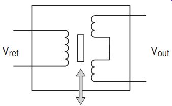
FIG. 3.5: Inductive sensor circuit diagram.
This sort of inductive position sensor is very commonly used in a class of devices called linear variable displacement transducers (LVDT). These transducers can have very good accuracy (much better than 1% of the total range of motion, which is commonly called "stroke"), and are often used for precision position measurement applications, such as flap and rudder position measurements on aircraft.
One method of analysis for these systems is based on a magnetic circuit analogy, in which the inductance is seen as the sum of a series of "reluctances," which are individually defined as
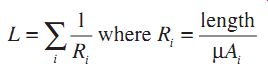
where the length is of a segment of the magnetic circuit, the µ is the permittivity of that segment, and Ai is the cross-sectional area of that segment.
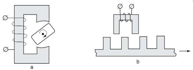
FIG. 3.6: A magnetic circuit example #1.
An example of a device that relies on a magnetic circuit is shown in FIG. 3.6. A coil is wrapped about one part of a ferromagnetic structure. The magnetic field creat ed when there is a current in the loop is almost entirely confined within the magnetic material. A moving ferromagnet is placed within the extended legs of the structure.
Since the magnetic field will mostly pass through the moving element, the length of the total magnetic circuit is dependent on the position of the moving element. Since the reluctance of the circuit is the sum of the reluctance of the elements, the total inductance that is measured at the coil is also dependent on the position of the moving element.
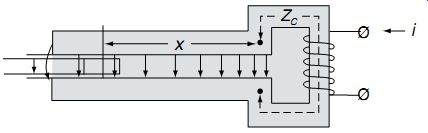
FIG. 3.7: A magnetic circuit example #2.
Alternatively, these systems may be used in situations where the reluctance is a continuous function of the position of a moving element, as in FIG. 3.7. The reluctance is inversely proportional to the permittivity, and the inductance is inversely proportional to the sum of reluctances, so the total inductance is maximized when the magnetic circuit has a minimum of air gap. In these systems, the inductance of the total element is increased by a large factor when the moving element is positioned so as to minimize the air gap.
4. Magnetic Field Sensors
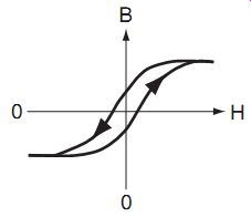
FIG. 4.1: Hysteresis loop.
There is another class of instruments used for detection of static magnetic fields. Magnetometers can be made in several ways, and here we will review a couple of specific devices that are of widest commercial use.
The flux gate magnetometer relies on measurement of the behavior of a ferromagnet-filled inductor. In the absence of external magnetic fields, current passed through the coil causes the formation of a magnetic field, which acts to polarize the ferromagnetic material. In general, the memory of the ferromagnetic material causes a hysteresis in the relation between the applied field and the polarization of the ferromagnet.
We can see this by thinking about the starting situation, where the ferromagnet is unpolarized and there is no current. If a current is applied, it polarizes the ferromagnet. As the current is increased, the polarization increases until saturation. Now, the current may be reduced to zero, and the resulting situation will include some residual polarization of the ferromagnet. If a current in the opposite direction is applied, the polarization is reversed, eventually saturated, and retains some residual reverse polarization when the current is again turned off. A graph of magnetization (B) versus applied magnetic field (H) is shown in FIG. 4.1.
The applied magnetic field is proportional to the current through the electromagnetic field and we see that the magnetization of the core responds to the applied field with hysteresis.
In the absence of an external magnetic field, the hysteresis loop is perfectly symmetric, and the graph of voltage versus current would only include the odd harmonics of the drive frequency.
If there is an external magnetic field, the hysteresis loop is shifted away from the origin. This is because there is a residual applied magnetic field when the current is off, due to the external magnetic field. One result of this is that the symmetry of the hysteresis loop is spoiled. If the I-V graph is analyzed, there will be a component at the second harmonic of the drive frequency, and the amplitude of this harmonic will be proportional to the component of the external magnetic field vector along the coil axis. Therefore, this device may be used to sense external magnetic fields. In fact, when properly constructed and wired, this sort of sensor can be very sensitive to small changes in external magnetic field. This class of magnetometers is generally used for space science missions, and for all precision terrestrial applications.
A miniature flux-gate magnetometer is available from Applied Physics Systems, featuring resolution of less than 10^-10 T/sqrt(Hz), very good linearity, and very small size. It is a fairly expensive instrument.
This style of magnetometer is also used for a number of prospecting applications. In several important applications, buried objects produce magnetic fields, and instruments that can measure local magnetic field gradients are very useful. Instruments available from Schonstedt feature a pair of flux gate magnetometers operated in a differential mode. If magnetic objects are positioned near the pair, the earth's magnetic field is distorted and the difference between the two magnetometers does not cancel perfectly. In this mode, the gradiometer can sense the presence of a magnetic object. This kind of instrument is commonly used by road-repair crews to locate buried cables prior to digging.
Another class of magnetometer is called the Hall effect sensor. In the Hall effect sensor, the transport of electrons through an electrical device is affected by the presence of an external magnetic field. As shown in FIG. 4.2, current flowing from the top to the bottom of a device is deflected to the right, causing a charge build-up, and a measurable volt age. This sort of sensing approach offers ease of fabrication as a substantial advantage, but does not offer the performance of the flux-gate devices discussed above. In general, a Hall effect sensor can measure down to about 5% of the earth's magnetic field.
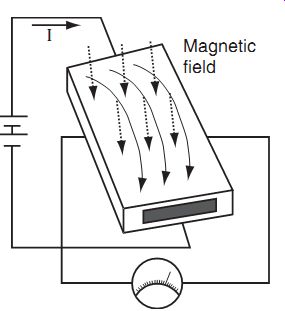
FIG. 4.1: Hysteresis loop.FIG. 4.2: Hall effect sensor.
Instead of measuring the build-up of a Hall voltage, it is also possible to measure the increased resistance of the device due to the deflected electrons. In this case, the Hall based sensor is called a magnetoresistor. Recent years have seen much research on materials for magnetoresistors at Honeywell and elsewhere. A very important advan tage of a Hall magnetoresistor is that the resistive film may be easily patterned into geometries that are easily connected into resistance bridges, as shown in FIG. 4.3.
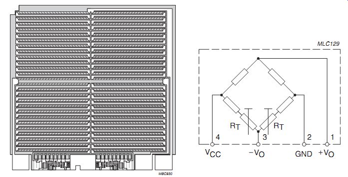
FIG. 4.3: Magnetoresistors: Resistive film patterned into Wheatstone
bridge on chip (offset trimmed to zero by RT).
A newer magnetoresistor material, which offers a larger magneto-resistance effect (called the Giant Magnetoresistance Effect or GMR for short), is being used for a number of applications. Several companies are marketing devices based on these new materials.
One very important application for miniature magnetic sensors is as the data-read head for disk drives. Clearly, improved sensitivity is important because it can enable increased storage density in disk drives. As a result, GMR read heads have become common on the newer generations of hard disk drives.
5. Summary
We have reviewed the basic principles of induction, and examined several examples of devices that use this principle to measure the position or presence of objects. We have also looked at flux-gate and magnetoresistance magnetometers, and looked at some products based on both. In general, a wide variety of magnetic sensor-based instruments are available. The emergence of thin-film sensors is important for the disk-drive industry, and other applications of thin-film magnetometers can be expected.
NEXT: Flow and Level Sensors
PREV: