A PRE-EMINENT PHONO PREAMP
AT LAST, I HAVE DEVISED what I consider to be my ultimate moving-magnet (MM) phono preamp. Al though this is only the third preamp article I have had published [1,2] many of my designs have never seen print. In light of all my experimentation, though, I think I can safely say that my new preamp, the P-100-mm, is the best I have done.
Design Philosophy
In designing my preamp, I considered the following parameters, which I have listed in order of their importance.
1. RIAA Equalization Accuracy. It has been proved that fractions of a decibel in frequency-response errors are audible in close listening tests.
Therefore, it is desirable to use precision design components and comprehensive design equations
(See Lipschitz’s discussion of RIAA (3) for an excellent analysis of design equations for the popular topologies.)
Note that the RIAA specifies the record/playback equalization only over a 20Hz to 20kHz bandwidth (Fig 1). Above and below these frequencies, the designer has no specific guidelines (Fig. 2). I prefer to continue the 75usec pole (roll-off) beyond 20kHz, mostly as a preventive measure (see design consideration 4). My research into what a typical record-cutting lathe actually puts on the record shows a -12dB/octave divergence from the 75usec pre-emphasis, beginning as low as 35 to 40kHz.
On the low end, I have adopted the IEC's proposed roll-off at 7,950usec (-=3dB at 20Hz). Strictly speaking, this differs from the true RIAA response by 3dB at 20Hz, but I have yet to hear a record or system that sounds better without the roll-off. This IEC pole is switchable on my reference preamp, so I have been able to make many listening comparisons over the years. If you disagree with me on this, you can easily shift this pole downward (see my section on “tweaks ”).
2. Dynamic Range. A properly designed preamp should be quiet enough not to impinge on the noise floor of the recording and still have satisfactory headroom to reproduce cleanly the largest signal it will en counter. While low-level hum is generally just a nuisance, low-level hiss can psychoacoustically interact with the signal, pad apparent reverberation and spectral content of low-level signals. Inadequate head room can compress signal dynamics and if severe enough, can cause audible distortions.
3. Input/Output Interfaces. Moving-magnet cartridges are relatively high-impedance transducers designed to be terminated by a fixed resistance (usually 47 k ohm) and some amount of fixed capacitance. The actual input impedance of the preamp circuitry should be many times greater, as it will be in parallel with the passive in put termination and can cause errors if it is too low or it changes over the audio band.
The preamp output impedance should be low, flat and preferably resistive. For hi-fi applications, a preamp will typically see loads of 10k or greater. In professional applications, it is possible to encounter 600 ohm loads. The preamp should also be comfortable driving reactive loads, as it may be connected to trans formers (inductive) or long runs of cable (capacitive), not to mention some rather exotic hi-fi cables.
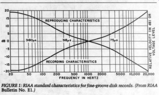
FIGURE 1: RIAA standard characteristics for fine-groove disk records.
(From RIAA Bulletin No. E1.)
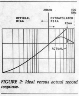
FIGURE 2: Ideal versus actual record response.
4. Linearity and Out-of-Band Signals.
The preamp should reproduce all in-band signals with no audible distortion. It should pass or attenuate (preferably the latter) any out-of-band signals without generating spurious artifacts that fall within the audible pass band or that can interfere with other signals in the system such as tape bias and digital sampling rates.
5. Separation. While cartridges are not known for outstanding separation, the preamp should be enough better than the best cartridge at all frequencies not to degrade the combined result.
The Design
One luxury of designing a preamp at this late stage in the life of electro mechanical recording is the benefit of history. Most of the obvious problems have been reported and solved.
This design is a distillation of several different techniques synergistically combined to take advantage of the best features of each without a significant increase in complexity. Figure 3 is the schematic diagram for the P-100-mm preamp, while Figs. 4 and 5 show the circuit board pattern and stuffing guide, respectively.
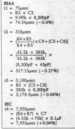
To ensure near-ideal input termination and wide dynamic range, I have specified a low-noise N-channel JFET (2SK117). This FET is quieter than any integrated circuit op amp and has extremely high input impedance. It is configured as a simple common-source gain stage. Instead of using the familiar Drain resistor, however, I have loaded it with a resistor and a capacitor in parallel (R3 and C2). This RC effects the 75usec (-3dB at 2,122Hz) RIAA roll-off.
NPN transistor Q3 forms a fixed DC current source that increases the current density of the input FET (Q1) for improved linearity and maximum in put dynamic range. PNP transistor Q2 also forms a DC current source and is controlled by a servo loop, with op amp A2b centering the out put of op amp Al for a symmetrical signal swing.
In the equalizer stage, opamp A1, with R4, R5 and C5, defines the 3,180 usec and 318usec RIAA time constants. C4 provides additional roll-off above 50kHz and trims in the 318 usec time constant.
Because the output of Q1 looks like a current source to Al, the op amp will be running at an effective closed-loop gain of about 14dB for a high loop-gain margin and thus extremely accurate playback equalization. Since the passive 75usec pole low-pass filters the signal before it reaches a negative feedback stage, this preamp cannot be slew-rate limited. The limiting factor for high frequency headroom is the input stage overload, which occurs at about ... 3.5V peak-to-peak. As that is well above the level at which the output would clip for any in-band signal (20Hz to 20kHz), the preamp's input headroom can be characterized as the output clipping point divided by the RIAA equalization normalized for 40dB of gain at 1kHz.
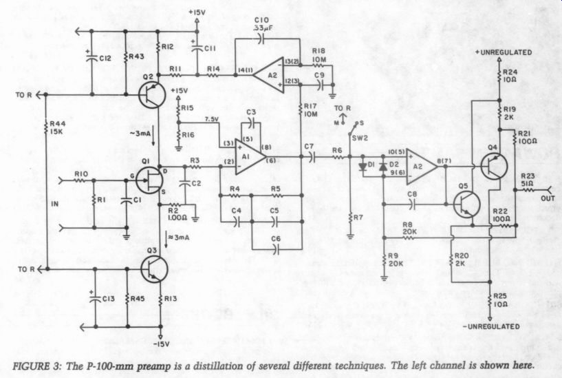
Fig 3
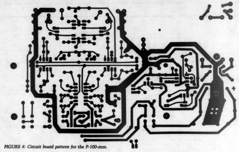
Fig. 4
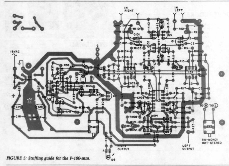
Fig .5
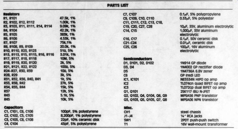
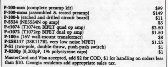
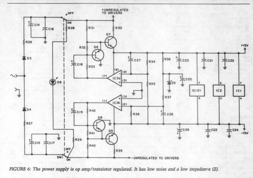
FIGURE 6: The power supply is opamp/transistor regulated. It has low noise and a low impedance (Z).
C7, R6 and R7 form the IEC high pass pole at 7,950usec (20Hz). A switch contact shorts the junction of R6 and R7 of both channels when mono operation is desired. Op amp A2a, with transistors Q4 and QS5, form a class AB output driver with approximately 5mA of bias current.
This driver will remain class A for any possible hi-fi load, and because the drivers are inside the feedback loop of A2, they will produce extremely low distortion even when operating in class B (above 6V peak to-peak into 600 ohm).
My simple opamp/ transistor regulated power supply (Fig. 6) maintains a reasonably low impedance over the audio band. But power sup ply impedance is only half of the equation. I have also designed each stage with a high power supply rejection ratio (PSRR) in mind. The cur rent sources in the input stage effectively isolate the audio signal path from power supply disturbances.
Both op amps in the forward audio path are operated at low closed-loop gains. This is important, as op amp PSRR is referenced to the input and degraded by high closed-loop gains.
The driver transistors in the output stage draw their current from the unregulated power supply, isolating the regulated supply from output load currents, a common source of difficulty when driving capacitive loads.
Finally, the passive 75 usec pole attenuates high-frequency transients before they can get to the regulated power supply to cause problems.
Tweaks
Although this preamp approaches my view of perfection, I anticipate that a few of you might not share my opinion. For that reason, I have added a few extra pads to the board and have tried to use common parts layouts to facilitate modification and substitu-
--------------
Eq Design Equations
------------------------
Parts List
(see above)$1 MasterCard and Visa accepted, add $2 for COD, $1 for handling on orders less than $10. Georgia residents add appropriate sales tax.
-----------------------
[…]
A1 is laid out for an NE5534, but this pin-out is very common. You […]
Anyone wishing to lower the low frequency cutoff should increase the value of C6. Unless you have a ready source of high-quality film capacitors, I would recommend paralleling the stock 0.1uF polypropylene with a Mylar. Adding another 0.1uF cap will bring the low-frequency -3dB point to 10Hz with no sonic deterioration.
The mono/stereo switch uses point to-point wiring, SO anyone not wanting that function can omit the wires.
You can add gain to accommodate high-output moving-coil cartridges by dropping the value of R2. Substituting a 49910 resistor will provide another 6dB of gain, with no performance penalty gain has been increased a like amount. The input headroom (in decibels) is constant. While it is possible to increase the gain further by reducing the value of R2 even more, I do not recommend trying to interface directly with low-output moving-coil cartridges. The extra 20 to 26dB of gain will compromise the system noise floor. (See reference 2 for a dedicated moving-coil preamp design.) Note: If the servo will not pull in after you have changed R2, replace R12 with a trimpot and adjust for approximately 0V on the output of A3. Additional pads are provided at the inputs to facilitate connecting switchable or adjustable input loads.
Caveat
My years of working with phono preamp designs has led me to conclude that preamps are not the weakest link in the chain. If your cartridge is not healthy, you are wasting your time and money upgrading the preamp.
Begin with a good cartridge. I know it is difficult to sort through the garbage, but do your homework, read the reviews and listen to as many cartridges as you can. Do not automatically assume that more expensive is better. I have heard great $20 cartridges (e.g., Grado) and mediocre $200 cartridges (which shall remain nameless).
Next, be aware that cartridge alignment, tracking force and antiskating adjustments can cause serious amounts of very audible distortion.
Mistracking can cause accelerated record and stylus wear. Get a test record and use it.
Check that the cartridge is properly loaded. Some are more sensitive than others, but a capacitance mis match can cause frequency response ...
------------------
Listening Tests
by Patrick. Amer
At the editor's request, I have evaluated John Roberts's P-100-mm prototype. It is a phono section only, so I played it through the auxiliary input of each comparison preamp, then compared it with the phono section of that preamp. The comparison units were the Fujitech A-1033 tube integrated amplifier, the Fujitech A-502 and the Phoenix Systems P-10 (which I reviewed in TAA 3/83, p. 48). In each case, I played the test records on a Ken wood D-500 turntable with an SME 30091 arm and a Dynavector cartridge. I split the output with my Jung-type active crossover at 375Hz, with the low-pass signal going through a POOGed Hafler 500 to the woofers and the high-pass signal going through the amplifier section of the A-1033 to the mid range and tweeters of my IMF TLS 501 speakers.
The P-100-mm prototype shared many of the sound characteristics of the Phoenix P-10. The sound was clear and clean, but dry and forward. The ambience sounds, which indicated depth of image on the Fujitech reference phono sections, were muddled and distorted on the test unit, suggesting indistinctness rather than depth. On the Accent recording of German Chamber Music (the Kuijken Quartet, Acc 8019), the flute sounded hooded rather than recessed, while on the A-1033 phono section, its location was clear.
The dryness of the sound made string instruments sound some what wiry. On The Scholars' “When Winds Breathe Soft” (L'Oiseau Lyre DSLO 33), the voices sounded shallow, without body or support. This effect was ex acerbated by a thinness of sound in the lower midrange, which weakened the support of the cellos, gam bas and baritones. In contrast to both the tube and solid-state Fujitech preamp phono sections, the P-100-mm does not seem to have the ability to handle complex sounds without mushing them together into a composite sound. It sounded fine when a single voice or instrument was playing, but it was unable to follow a second or third voice or instrument with fidelity.
On The Scholars' recording noted above, the P-10 had better balance than the P-100, with a full bottom, and the sound was not as mushed or dry as on the prototype.
On the Haitink, Amsterdam Concertgebouw recording of the Mahler Third Symphony (Philips 802 711/12), the P-10 was not as flat and shallow as the P-100-mm, and it had better trombones and tympani. Unlike the Fujitech pre amps, the Jung-White PAT-5 and several other comparable preamps, neither the P-10 nor the P-100-mm was able to re-create the open sound stage of the Philips recording.
In summary, I think the P-100-mm is still an experiment in process that needs additional work.
Mr. Roberts replies:
I agree with Mr. Amer that the Phoenix P-100 and P-10 sound similar. I think the P-10 sounds excellent also. In response to the criticism of weak low bass, I stand by my decision to incorporate the IEC pole (-3dB at 20Hz). I will, however, include the extra 0.1uF polyesters in the kit for those who wish to defeat it (see the Tweaks section of my article).
Since Mr. Amer listened to the P-100, I have reduced the input stage gain approximately 4dB.
While this will further improve linearity, I do not wish to speculate on the sonic effect, if any, on Mr. Amer's reported impressions.
-----------------------
...errors in the top octave and affect transient response.
By way of general maintenance, make sure that you keep your records and stylus clean. Check the stylus periodically for wear. Also check for loose wiring in the tonearm. Gold plated interconnect cables will not help if the wires on the cart. body are loose. If you find loose wires in your headshell, you can usually tighten them by removing the clips and squeezing them gently with long nose pliers before reinserting them on the pins. Be careful not to crush the wire clips, as they are fragile.
This circuit will exhibit a turn on/off transient that might be dam aging to speakers in high-powered systems. For that reason, I suggest powering up the preamp before the power amplifier and powering it down after. In fact, I prefer to leave my low-level electronics turned on.
Unlike tubes, semiconductors do not wear out and are stressed more by thermal cycling on and off than by remaining constantly on. There is even some evidence that semiconductors can get quieter after running for some time. (This is called “self-annealing. ”) Although this is just an overview of my preamp design, I think it gives you a good idea of how the P-100 mm works. As I said earlier, I think it is the finest unit I have built. mc you agree.
REFERENCES
1. Roberts, J.H., 'Build a Disco Preamp/ Mixer,’ Popular Electronics (Volume 14, Number 3), September 1978, pp. 61-71.
2. Roberts, J.H., “A High Performance Phono Preamplifier, ” Popular Electronics (Volume 19, Number 3), March 1981, pp. 79-84.
3. Lipshitz, S.P., “On RIAA Equalization Networks, ” JAES (Volume 27, Number 6), June 1979, pp. 458-481.
4. Standard Recording and Reproducing Characteristic, RIAA Bulletin No. E1 (rev. November 6, 1978).
5. Holman, T., “New Factors in Phonograph Preamplifier Design, ” JAES (Volume 24, Number 4), May 1976, pp. 263-270.
6. Motchenbacher, C.D. and F.C. Fitchen, Low-Noise Electronic Design (New York: Wiley, 1973), pp. 88-90.
--------
By John H. Roberts
----
Also see:
Six-Transistor Ultra Low-Noise MC Phono Preamp
All-JFET MM/MC Phono Preamp, Part 1
Ultra-Low Distortion Phono Preamp: The LP-797
LOW-DISTORTION, LOW-FEEDBACK POWER AMPLIFIERS, by R. N. Marsh
AR SYSTEM DRIVES NEW TURNTABLE, By Gary A. Galo