by B. Pohelhad
Tyger! Tyger! burning bright In the forests of the night, What immortal hand or eye Could frame thy fearful symmetry! from "The Tyger" (1794) by William Blake (1757-1827) LAKE'S VIVID IMAGERY easily fits the reputation of Tigersaurus. My audio interests were born during the
''super-amp revolution' of the early 1970s. Hearing the difference between 20W/channel and 200W was the beginning of my fascination with giant power amps. By 1977 I had found the courage (and the cash) to plunge hands first into one of the mammoth power amp kits.
I salivated over brochures from Great American Sound, Dynaco, Heathkit and Southwest Technical Products Corporation. I finally narrowed down my choice to either the Dyna Stereo 400 or SWTP''s monophonic 210/A ''Tigersaurus."' In those days Dyna gear was distributed by all the major retail audio outlets as well as Lafayette stores, so it was easy to hear and see the big Dyna amps. But Tigersaurus information was scarce.
---------
ABOUT THE AUTHOR: Ben is 39, has a BS in chemistry and works in the pharmaceutical industry. Colleagues occasionally regard him as something of a witch doctor, since he specializes in seeking new medicines from exotic plants and animals from around the world. He has published a dozen scientific articles in the fields of liquid chromatography and spectroscopic structure elucidation. An occasional contributor to Audio Amateur since 1984, Ben has been involved in ''roll your own'' audio for 14 years. Ben takes credit for the photos in this article.
------------------
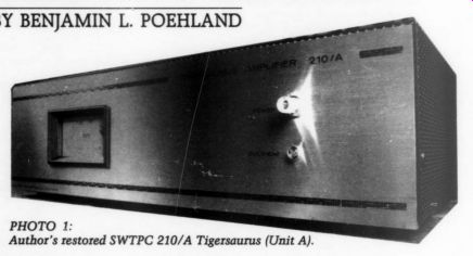
PHOTO 1: Author's restored SWTPC 210/A Tigersaurus (Unit A).
------------
Fortunately I was enrolled in an audio course taught by an engineer at the audio outlet where I had bought my equipment. The course introduced me to the cream of the local audio cognoscenti, and the near universal response I received to Tigersaurus queries ran something like, 'Oh, yeah, all those Tigersaurus amps just blow up.'' People who owned Tigersaurus could not tell me what one sounded like, but horror stories of fires, blasts, smoke and sparks abounded-and that was enough for me. So my first audio construction project was a Dyna ST-400. After several rounds of upgrade mods I still use that 400 today. But I always wondered about Tigersaurus.
Intimidated as I was by vivid tales of the monster amp that spouted flames, vestiges of curiosity about Tigersaurus remained. Could an amp really be that bad? By 1981 SWTP had abandoned the audio market, and Tigersaurus became an extinct audio dinosaur. Meanwhile my interests had diverted toward signal processors, and I all but forgot Tigersaurus until 1988.
During a conversation with another 'old timer' the subject of SWTP came up, and again I was regaled with tales of the Flaming Tyger. He was glad to un load his burned-out Tigersaurus hulks for a few bucks, and I welcomed the opportunity to investigate the mystery of the fiery amp at a price low enough to support a high expectation of disappointment. I arrived home one day to find The Beasts slouching at my front door.
Beast Encounters My very first meeting with Tigersaurus was unpleasant. Upon attempting to pick up one of the units [ immediately almost dropped it. Tigersaurus weighs about 32 pounds, and as I lifted the rectangular case I was unprepared for the uneven distribution of mass: 90% of the weight was on the right-hand side where the heavy power transformer is mounted. Worse, as the amp slid from my grasp the sharp edge of the perforated metal cover caught my shirt and ripped off half the cuff from my sleeve.
These amps were truly uncivilized! Warily eyeing them on my kitchen table, I noticed another uneven center of mass problem: neither unit sat level.
The heavy transformer had permanently squashed the right side rubber feet, giving the amps a pathetic lop sided appearance.
If by its external appearance Tigersaurus conveyed a poor impression, that was nothing compared to the interior carnage. The inner surface of the cages on both units was coated with fine, hand-blackening soot. The main circuit board in both amps was an audiophile's nightmare: a large area of the glass-epoxy in the vicinity of the ceramic bias resistors was badly scorched, here and there resistors appeared to have exploded, and the periphery of the scorched area contained remains of components too charred and melted to identify.
In one amp the wiring harness attached to the output heatsink appeared to have caught fire, leaving behind brittle threads of oxidized copper wire to which a few bits of charred insulation still clung. I pulled the B+/B- fuses from both units and found all of them violently blown, their filaments completely vaporized. I have repaired dozens of blown amps over the years, but never had I witnessed such a scene of cataclysmic destruction. The evidence confirmed the horror stories I had heard: the fiery reputation of Tigersaurus was apparently well earned.
Audio Archaeology
Appalled by the mess in these blasted hulks, I was overwhelmed by the challenges inherent in restoration. I sought information on these dinosaurs before committing my full resources to what looked like a major project with doubtful outcome. Technical information on Tigersaurus was sparse (I was unable to find original construction manuals from SWTPC), but what I found convinced me that a restoration attempt might be a worthwhile effort.
Dan Meyer's original Radio-Electronics construction article! was an essential prerequisite to any reconstruction work. As I pored over this article I made some intriguing observations.
First, Tigersaurus incorporates design features remarkably similar to a classic of solid-state power amplification: Ampzilla. Even today Ampzilla's sound quality remains a legend generally attributed to its design innovations.? Dual differential inputs with emitter degeneration fed by high-impedance current sources, direct-coupled full complementary-symmetry from input to out put, a constant current source in the driver stage, split power supplies, and series-connected output devices were all hailed as Ampzilla's contributions to the world of high-powered bipolar sound.
Tigersaurus incorporates all of these innovations, yet Dan Meyer published Tigersaurus fully nine months before Jim Bongiorno's landmark Ampzilla article.? Another surprising thing was the high current capacity of the Tigersaurus output stage: 60A. Specifications for Ampzilla and the Dynaco 416 output devices add up to an output current only half that of Tigersaurus. High-cur rent output did not become a fashion able selling point until the early 1980s.
Was Dan Meyer ahead of his time? I think he was, and I believe Dan could lay claim to a measure of audio immortality as the framer of the ''fearful symmetry'' of Tigersaurus: one of the first high-current output designs.
I also pulled out Walt Jung's truncated attempt to review Tigersaurus in Audio Amateur. Despite the generally negative tone of Walt's commentary, I derived great encouragement from it. In Walt's hands Tigersaurus merely behaved badly, exhibiting parasitic oscillations, high background hum levels, and a buzzing power transformer. Walt's report made no mention of the amps having set fire to his house. I took this as a positive sign, my first glimmer of hope that Tigersaurus could be turned on and listened to without erupting into a household volcano.
It wasn't much to go on, but armed with this scanty knowledge I now felt it might be possible to restore the dead Tygers to life. Eyeing the blasted car casses, I resolved to ferret out whatever flaws might have contributed to their violent end. And perhaps, with a little luck and blessings from audio Valhalla, I might wind up the ecstatic owner of a pair of superb classic superamps.
A Post-Mortem
As I prepared to plunge into the blasted hulks, I counted a few lucky breaks.
Cosmetically the amps were in good shape-clean front panels, no major scratches or dents in the sheet metal or cages. Next I pulled, inspected and tested the major power supply components: transformers, filter caps and bridges. They all checked out fine, and spray cleaner easily removed sooty stains. This was a relief, since sheet metal and power transformers are the toughest parts to replace. The rectifiers were mounted crookedly, since no chassis hole existed for the positioning pin. I filed off the positioning pins from both rectifiers and coated their bottoms with thermal compound in preparation for reinstallation.
I continued stripping the remaining power supply components: fuseholders, wiring, line cords, power switches, overheat indicators and thermal cut outs. Although the cutouts had been mounted without thermal grease, they tested good, giving an audible click when I touched them with a hot solder ing iron. The heavy three-wire line cords were in good shape.
One of the power switches was defective (broken toggle mechanism), and Tigersaurus had no pilot light. At a local Radio Shack store I found a unit with acceptable electrical specifications that had a built-in pilot light and was a good fit to the mounting hole in the Tigersaurus front panel. I replaced the switches in both amps with this part.
Cold Connections
Next I loosened the main circuit board in each amp, de-soldered the remaining wire connections and set the boards aside. I carefully removed the heatsink wiring harnesses (Photo 2). Each amp has two of these harnesses; one goes to the positive outputs, the other to the negative ones. The harnesses were com posed of #20 stranded wire with a gray vinyl insulation. Wire terminations were solder lugs and mechanical pin socket connectors covered with heat shrink insulation. On a few of these pin connectors the insulation did not fully cover the connector, and on one the ex posed connector exhibited damage due to arcing or a short circuit. This connector had probably been jammed down too far onto the output transistor pin and made undesirable contact with the metal case (collector) of the output transistor.
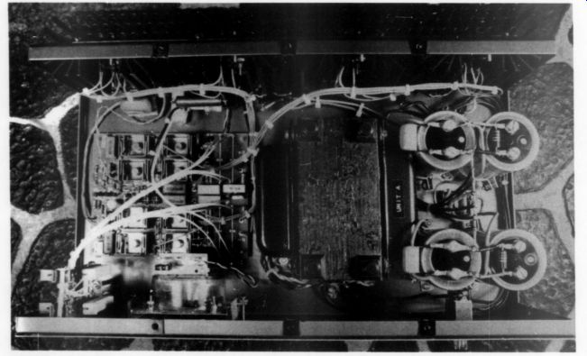
PHOTO 2: Tyger guts.
As I completed my inspection of these wires it occurred to me that the harnesses comprised a critical component of the amplifiers. Through their fragile mechanical connections must flow the supply voltages and heavy currents which drive the output load. A bad connection here could spell disaster. And many of the pin connectors were fouled with thermal compound, seriously compromising their conductivity.
I removed the heatshrink insulation from the pin connectors and reheated the solder connections to all the pins and lugs, revealing a total of five cold solder joints among the four harnesses (eek!). Before applying fresh heatshrink insulation I cleaned the pins in methylene chloride (from the hardware/paint store) outdoors-to avoid the fumes.
This solvent treatment is the best way I know to remove gummy deposits of silicone grease and zinc oxide from metal parts.
Contaminants Counteracted
I replaced burnt wire with suitable lengths cut from the output inductor wound around one of the filter caps. I carefully labeled each wire in each harness with the appropriate letter code identification to ensure correct connections to the output transistors. For good measure every pin and lug was liberally treated with 10% Cramolin Blue in isopropanol. The rear panel and heatsinks were treated next. I removed the output transistors from both amps, taking care to save all the insulators, sleeves, screws and hardware. Here I encountered more evidence of novice construction technique: all the output devices had been sloppily mounted with an excess of thermal compound which was oozing out everywhere, but the critical thermal bias tracking diode had been mounted with no grease at all! All the transistor mounting hardware was heavily contaminated with thermal compound that had to be removed.
I dumped the hardware into an old pickle jar, poured in some methylene chloride, screwed on the lid and shook it up. I poured off the solvent into a waste container (NOT down the drain!), added fresh solvent and repeated the process a few more times until the wash was clear. Outdoors, I spread the clean hardware on a towel to dry. I placed the waste container and pickle jar outside a few days until the solvent had all evaporated, then I capped them and discarded them in the trash.
Three different types of TO-3 insulating wafers had been used to mount the outputs, and some of them looked ragged. I trashed the lot and replaced them all with new mica insulators from my stock (obtained from Hanifin).
I wiped the grease from the output devices and checked them on a Radio Shack quick-tester, finding ten of the original sixteen still good.
Mixed Blessings
I also found two different types of out put devices had been used. SWTP specified Motorola MJ802/4502 transistors, but Texas Instruments 2N6328/6331s were present as well. I checked specs on the 6328/6331 devices' and found they were a lower hFE version of the 802/4502 but were close enough to make acceptable substitutes. There were enough good 6328/6331s to make one amp. I had some 802/4502s on hand but still had to order two 4502s (Hani fin) to complete the complement for the second amp. When the new 4502s arrived I had expected to receive Motorola units, but instead they were marked "PECOR." I was unfamiliar with PECOR but accepted the transistors anyway--and later regretted it.
Finally I inspected and tested the IN3754 bias tracking diodes. On one diode an excess length of wire from a crooked solder connection was in firm contact with the TO-l metal case-an unhealthy situation. I re-soldered the wire leads to the diodes, encased the joints in fresh heatshrink and slipped a 5-inch length of protective insulating sleeve over the wire leads.
I completed the chassis stripping by removing and discarding the rubber feet and removing the remaining hardware and output meters. The meters and their associated circuit boards were in good condition. Each cage and chassis was then given a good scrubbing in the kitchen sink with 409 cleaner and Q-tips to remove the last stubborn traces of thermal grease from heatsink holes.
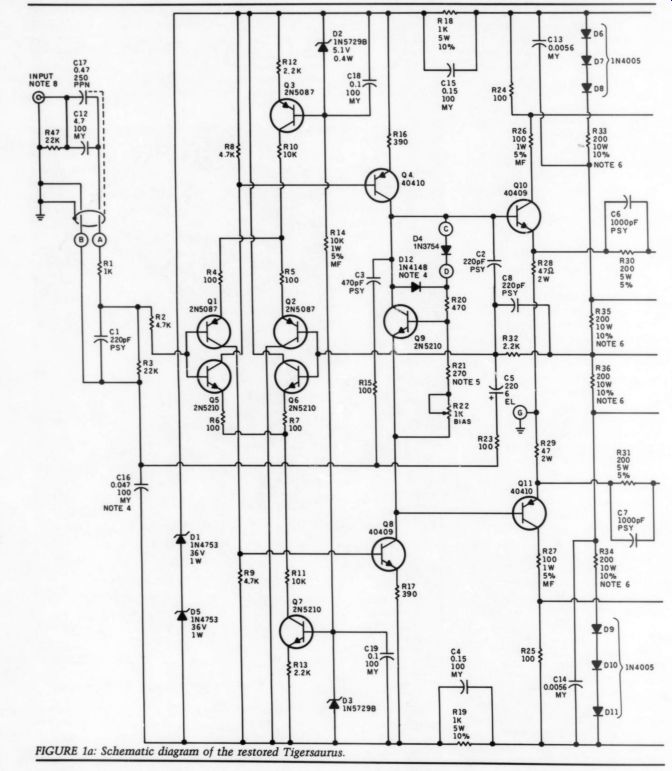
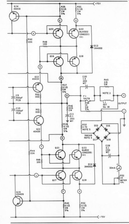
FIGURE 1a: Schematic diagram of the restored Tigersaurus.
The thin from dress panel on one chassis had begun to peel off so I restored it with Super Glue.
With the chassis and associated components now squared away I turned to the circuit boards.
Parts Parameters
Without hesitation I trashed all the small resistors and ceramic capacitors (many of which were trashed already). The eight large 2000 bias resistors checks OK, but all twelve 1NSQ60 bias diodes were completely roasted so I substituted 1N4004s. All the small TO-92 transistors checked OK, but I found five of the 16 RCA 40409/40410s to be defective and replaced them (Hani fin). Removing the RCA devices required considerable skill and patience to avoid damage to the foil runs; I employed a ''solder-sucker'' bulb to good advantage here. The remaining large resistors, zener diodes and capacitors all checked good.
After clearing excess solder from the foil traces and component holes the boards were bare but appeared badly barbequed. A mild scrubbing with Comet cleanser and a Scotch-brite pad in the kitchen sink completely re moved blast marks and sooty smears: the boards came up looking nice.
Severe scorch marks still lingered in the vicinity of the bias resistors and 4753 zeners, but even in these areas the G-10 material was structurally intact, and all the original silkscreened parts locations were legible. On the foil sides the traces were all intact, though the foil runs were apparently etched from thin 1-oz.
stock and were bare copper and thus susceptible to corrosion. Still, thin unplated foils were something I could deal with.
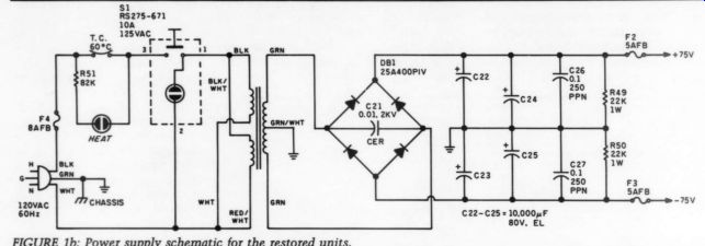
FIGURE 1b: Power supply schematic for the restored units.
Up to now my labors had largely been an act of faith: I had no way of knowing what I would find when I began my post-mortem of the Tygers.
I paused and surveyed my progress with a growing sense of confidence. Damage to the amps had been extensive but was not as bad as it looked, and I had salvaged many critical components. With a stock of replacement parts on hand, and good boards, sheet metal and power supplies, I began to believe I had a fighting chance at success. Most encouraging of all, my post-mortem had uncovered many flaws in design and construction that could be easily remedied. Frustration and much labor still lay before me, but as I began the reconstruction phase of this project I experienced that tingling sense of expectation and excitement that only audio builders can know.
Flaming Tyger Taming
I began re-stuffing the circuit boards with due regard for thermal dissipation.
---------------- NOTES:
1. All resistors 2W carbon film, 5% unless noted.
2. Capacitor types:
MY = Mylar PPN = polypropylene
PSY = polystyrene
PCB = polycarbonate
EL = electrolytic Cap values are in uF unless noted.
. May be replaced with Sound Values part
#453001.
. Parts added to later production units by SWTPC.
. Early production units may have different values.
. Off-board bias stack.
E = Ground-bus connection.
. Sound Values #355001 or similar insulated RCA socket.
---------------
The interior of any high-powered amp is a thermally stressful environment, so even the most noncritical resistor should be at least a quality half-watt carbon film type. Thus I upgraded all the 10%, 0.25 W resistors to 5%, half watt. In most instances these up grades provided a generous margin of dissipation and thermal stability. How ever, I identified two situations where the half-watt upgrade was mandatory, and another situation where it was in adequate.
A quick Ohm's Law calculation for the 22k resistors R43 and R44 (Fig. 1a) shows each of these components must continuously dissipate about 0.25W.
Thus, upgrading these resistors to 0.5W raises their derating factor from an unacceptable 0% to a much safer margin of 50%. In the case of the 10k resistor R14, the situation is almost scandalous. Here a measly quarter-Watt was required to dissipate nearly half a watt! The location of this resistor is critical, as it provides bias to the differential input current sources. Consequently I upgraded this component to a 5%, 1W metal oxide unit mounted one quarter inch above the board for a total derating factor better than 50%.
There was one more specific resistor upgrade I performed. The 1000 resistors R26 and R27 were originally 10% com position units whose measured values were beyond tolerance (86 ohm and 153 ohm).
Composition types are notorious for doing this. Given the critical role of these resistors in limiting output drive current, I also upgraded these to 5%, 1W metal oxide types for improved stability.
Heat Defeat
All the other large resistors were remounted in their original positions except for the four 200-ohm bias resistors R33-36. An Ohm's Law calculation for these resistors shows they must constantly dissipate a collective total of about 26W. From an electronic point of view that's an enormous amount of heat, enough to charbroil not only the circuit boards but also all the components in the immediate vicinity (which is what happened). Clearly these resistors had to be mounted some distance away from the board, so I set them aside temporarily.
I remounted all the semiconductor components in their original positions.
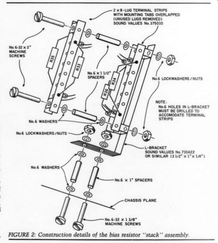
Fig. 2: 2 x 8-LUG TERMINAL STRIPS WITH MOUNTING TABS OVERLAPPED (UNUSED LUGS REMOVED) SOUND VALUES No.375010 --- NOTE: No.6 HOLES IN L-BRACKET MUST BE DRILLED TO ACCOMODATE TERMINAL STRIPS ----L-BRACKET SOUND VALUES No.710422 OR SIMILAR (3 1/2" x1"x 1/8")
Noting that the 1N4753 zeners (D1 and D5) are operated at the upper limit of their power ratings, I mounted them as high off the board as their short leads permitted and layered extra solder on their foil connections.
As I replaced capacitors I wanted to ensure that all the units I used had reasonable thermal stability, low di electric absorption, low leakage and good RF characteristics. These requirements precluded the use of ceramic capacitors anywhere on the boards.
Capacitors C1, C2, C3 and C8 were all polystyrene types that were retained.
Original 470pF ceramics C9 and C10 were replaced with 500pF polycarbonates. Ceramics C6 and C7 were replaced with 1000pF polystyrenes.
Original 0.005 uF ceramic bypass caps C13 and C14 were replaced with 0.0056uF Mylars.
Rolloff caps C11 were quality 250V Mylars that somehow survived toasting and were reused after checking OK on my cap meter. Bypass caps C4 and C15 were originally 0.1uF dipped Mylars that I discarded because they had contacted hot resistors R18 and R19 and partially melted. To ensure adequate clearance I replaced these with 0.15uF block-style Mylars I had on hand. Zener bypass C16, originally a bulky 0.01uF dipped Mylar, was replaced with a .047uF block-style unit. The 220uF electrolytic caps C5 were tested, found good, and reused.
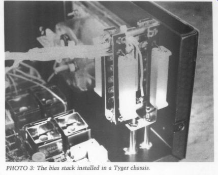
Photo 3
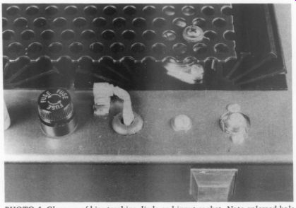
PHOTO 4: Close-up of bias tracking diode and input socket. Note enlarged hole for isolation of socket ground-shell. L-bracket fastening safety cover to extruded fin is faintly visible through cover perf-holes.
Board stuffing completed, I then had to deal with the problem of the thin foil traces. I carefully layered a thick solder plating on all the foil runs. Unfortunately this operation left gobs of flux on the foil sides of the boards. Excess flux introduces stray capacitance that can cause frequency instability, and recently it was suggested that flux might affect sound quality by generating low-level noise currents between foil conductors. I removed flux by going outside, holding the boards vertically over a container and vigorously brushing the foil sides with a varnish brush dipped in acetone (from the hardware store- caution, highly flammable). I avoided potential solvent damage to the component side by first stuffing all the unused board holes with toothpicks. Foil patterns came up thick, clean and shiny, with the built-in corrosion resistance of solder.
Moving Day
Now for the chassis. I relieved the un even mass problem by swapping the locations of the transformer and filter caps; the more central location of the heavy power transformer resulted in a greatly improved weight distribution that made the amps a lot easier to handle. Since I utilized the two innermost original mounting holes, I only had to drill two new holes in the chassis to mount the transformer in the new position. I used the capacitor mounting brackets as templates for drilling new holes to mount the filter caps outboard of the transformer.
With this new arrangement, I found some extra chassis space-enough to mount two additional filter caps. I happened to have some 10,000uF/80V caps left over from another project and was itching to put them to good use. Unable to resist these primitive audiophile compulsions, I drilled additional holes in the chassis to mount the extra filters. In the center of the square formed by the four large capacitors there was enough space to mount the bridge rectifier, enabling the heavy power connections to be made through a minimal length of wire.
Secondary leads from the power trans formers were long enough to reach the rectifiers, but on the primary side the leads were now too short to connect directly to the power switch and AC line terminals. So I drilled another hole in the chassis bottom, halfway between the front panel and front surface of the transformer, for mounting a terminal strip to hold the intermediate wire connections to the transformer primary.
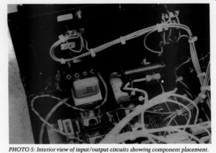
PHOTO 5: Interior view of input/output circuits showing component placement.
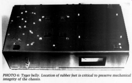
PHOTO 6
Hot Ohms
The last chassis modification turned out to be the toughest technical challenge of the project: mounting the four large 200 ohm bias resistors. The requirements were that these resistors be securely mounted in a mechanical con figuration permitting maximum air circulation, close enough to the main circuit board to minimize the lengths of required wire leads, yet far enough away so their blazing heat couldn't start another Tyger barbeque.
My confidence began to founder as I studied the chassis layout: at first examination no space seemed available.
To create some space I tried mounting the main board vertically along its short axis and found it protruded about a quarter inch above the chassis-good try, but no soap. With growing anxiety I searched through boxes of junk chassis parts and finally arrived at a combination of spacers, L-bracket, hardware and terminal strips to create the resistor ''stack'' assembly detailed in Fig. 2 and Photo 3. Connections from the stack to the PC board were made with quality #20AWG stranded wire whose insulation had to be able to withstand blazing temperatures without shrinking or melting-characteristics readily deter mined with a hot soldering iron.
Tigersaurus Resurrected
I commenced final assembly by installing all thermally sensitive components:
output transistors, bias tracking diode, bridge rectifier and thermal cutout. I took my time applying thermal com pound to the transistors and mica insulators, spreading the material in a thin even coat and maintaining a 0.5- inch margin around outside edges and connection pins. (My basic rule is: if the material squishes out past the edge of the insulator when you tighten down the device, you used too much.) I re mounted tracking diode D4 in a new location (Photo 4), using extra com pound to fill in the curved space be tween the diode mounting bracket and the edge of the heatsink.
Next I remounted the rear panel hard ware and line cord; the only chassis ground connection was made at the line cord input. At this time I had to make decisions regarding input circuit configuration and general ground-plane layout for the amps. The original Tigersaurus had two input connectors: one was direct-coupled, the other capacitor coupled through a tantalum electrolytic. A 10 k-O level control was also connected to both inputs. For all of my own equipment I have an ironclad rule: all inputs must be capacitor-coupled.
Input caps protect against DC offsets generated by upstream components, yet are usually cheap enough that you can use high-quality parts to minimize signal degradation without risking bankruptcy. For my input caps I selected nice Siemens 4.7uF/100V metallized polyester types in parallel with 0.47uF polypropylenes (both from Hanifin).
In stereo power amplifiers I use in put level controls during setup and testing when I want to hear only one channel at a time, but in mono power amps I find them unnecessary. The power switch makes a dandy attenuator and has the virtue of not adding sound-degrading mechanical contacts to the signal path-so I trashed the level pots. As a precaution against possible instability caused by the absence of resistance at the input I replaced the level pot with a 22 k-O resistor.
Lopping Loops Installation of the input socket brought me to consider the Tigersaurus grounding scheme. The original units had several separate grounds which were not centrally connected, with the main chassis ground being a relatively weak connection at the input socket. In my experience with other power amps I've come to favor a star-grounding scheme as the surest route to low noise and high stability. Consequently I enlarged the input socket mounting hole and in stalled an insulated socket with a separate heavy connection from the ground shield directly to the power supply ground bus.
The original level control mounting hole was occupied by the wire leads to the bias tracking diode, and the remaining hole was used for mounting a terminal strip to hold the input circuit components as detailed in Photos 4 and 5.
I continued the final assembly by in stalling the power supply components and wiring up the supply. I used heavy #14 stranded wire for all AC, DC and ground connections, and connected a length of solid #12 bare wire between the filter cap ground lugs to make the heavy ground ''bus-bar'' visible in Photo 2. All subsequent ground connections were attached here. I embellished the power supply with a few additional components. Ceramic buffer C21 protects the diode bridge against damage by inductive transients from the trans former secondary. Capacitors C26 and C27 improve overall stability by pro viding RF bypassing, a feature not pre sent in the original Tygers. Bleeder resistors R47 and R48 were added as a safety feature to hasten discharge of the potentially lethal reservoir capacitors upon removal of power.
Hum Hunts As I soldered various wires to the main PC cards I added more refinements. I made board connections from the input socket via a twisted-pair #22 computer type stranded wire encased in a foil wrapped shield in contact with a bare 'drain' wire, one end of which was connected to the socket ground. Doing things this way gave me a solid ground connection to the board and a good shield over both ground and signal in put leads. Connections from C11 and point ''G'' were made to the ground bus through #14 wire, and the output signal lead to F1 was also #14 wire.
Diodes D13 and D14 were added to the foil sides of the boards; they protect the output transistors against any reverse transients generated by woofer voice coil inductance.
I completed the electrical reconstruction of Tigersaurus by reconnecting the heatsink harnesses and wiring up the output circuits. The original output inductor consisted of a length of wire wound about one of the filter caps--an arrangement I viewed as an open invitation to hum pickup. I opted for the more compact, hum-resistant arrangement visible in Photo 5: 40 turns of #18 enameled wire wrapped around the body of R45, a 20/10W resistor.
I also added R48 to stabilize the out put by providing a constant standby load and ensuring that the amp will never see a load impedance higher than the value of R48 regardless of fluctuations in the actual load. I added Mylar bypass C20 to minimize degradation of high frequency response due to thermal modulation of the output fuse. Connections from the output binding posts to the meter circuit board were via a pair of #22 lightly twisted wires passed under the main board. For the final touch I treated all mechanical connections with Cramolin Blue.
Dressing Up the Beast
With their electrical innards refurbished the Tigersaurui were coming together nicely, but cosmetically they still looked brutish and uncivilized.
New replacement feet at the corners of the chassis brought an unanticipated result: the amps sagged in the middle.
Adding extra feet directly under the power transformer (Photo 6) prevented my Tygers from slouching and taught them to sit up smartly.
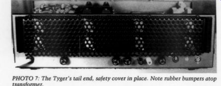
PHOTO 7: The Tyger's tail end, safety cover in place. Note rubber bumpers atop transformer.
Examination of the cages revealed the sheet stock had been stamped out with scant regard for the perf pattern.
This left hundreds of razor-sharp ragged edges that Tigersaurus could use to snag clothing and rip human flesh. I trimmed and filed the front and rear edges of both cages until they were perfectly flat, straight and smooth. On the sides it wasn't possible to make a straight edge due to the alternating hole pattern, but even so I managed to smooth it considerably. Using my fingers to detect sharp edges, burrs and snags, I removed them with a small round file used for sharpening chainsaw blades. Minus their raggedy edges, the Tygers assumed a neat and trim appearance and could no longer bite people.
As I fitted the cages to the chassis I became concerned about the proximity of the bare filter cap terminals to the cage; there was only about 0.5-inch clearance. Without mechanical support from the interior, a moderately heavy weight falling onto the cage could compress it downward just enough to contact the filter terminals and set off a holocaust.
The solution was to install additional square feet atop the power transformer, with an extra small round bumper on each square foot (both from Radio Shack), as seen in Photos 2 and 7.
These bumpers extend about 2mm above the plane of the chassis, so they are compressed slightly when the cages are tightened down. This arrangement provides excellent safety support and makes a snug fit free of mechanical resonance.
Color Scheme
I was not at all inspired by the cages' murky brown finish. A few coats of black Krylon semi-gloss spray enamel applied to the cage covers produced a striking transformation. The black covers enhanced the overall appearance by providing a black frame that really set off the front panel's brushed gold and black motif. As a result the amps acquired the handsome, aggressive, businesslike appearance you see in Photo 1. To preserve the effect I re placed the hodgepodge collection of original mounting screws with all black anodized #6 machine screws. Of course Tigersaurus was still a Beast. But I prefer my Beast well-groomed.
A final vestige of Tigersaurus' savage ancestry still remained. All the output transistors on the rear panel heatsinks were directly exposed. The cases (collectors) of the two sets of outermost transistors-Q17, Q19, Q20 and Q22- bear supply potentials of +38V DC. I hold it totally unacceptable for any voltage whatsoever to be present on the exterior of electronic equipment. The thought of tiny pink fingers probing... you get the picture. A type of plastic TO-3 cover exists that fastens by means of the mounting screws, but my at tempts to locate these came to nought.
[Mouser Electronics #561-E003 at 94¢ ea. -Ed.]
For inspiration I returned again to my packrat collection of junk chassis hard ware and fished out a nice 9"x12" piece of heavy gauge steel perf stock. After a few measurements and some head scratching I figured I could fashion two heatsink covers from this one piece of metal by cutting it in half lengthwise.
Armed only with a hacksaw, I made the cut with difficulty. I made the required 90-degree angle bend in each piece by tightly clamping the metal in a bench vise and bending it a little at a time with my bare hands.
The covers were fastened to the heat sinks with four #6 black-anodized ma chine screws set in holes drilled atop the heatsink fins. I used small L brackets and #6 black anodized hard ware at the sides. Following a primer coat I spray painted the heatsink covers the same color as the cages. Making and mounting these covers was an enormous effort, but the results visible in Photos 2, 4, and 7 were satisfactory.
As a side benefit the heavy covers added mass and additional surface area to the heatsink, thus improving overall thermal efficiency.
Continued next issue when the author will describe test procedures and performance results.
REFS:
1. This 250-Watt Hi-Fi Amplifier,"' Radio-Electronics, Dec. 1973, pp. 43-47.
2. Sweeney, Daniel and Steve Mantz, ''An Informal History of Solid State Amps," Audio, June 1988, p. 50.
3. Bongiorno, James, 'Get 400 Watts of Clean Stereo Power With Ampzilla,'' Popular Electronics, Sept. 1974.
4. Jung, Walt, 'Test Report: SWTPC 210/A 'Tigersaurus' Power Amp,'' TAA 2/80, p- 44.
5. Mcintyre, 3/81, pp. 18-21.
6. Motorola, Inc., Master Selection Guide, 1979, p. 157.
7. H. W. Sams Co., Transistor Specifications Manual 9th Edition, 1978, pp. 58, 147.
8. Olsher, Dick, ''Cable Bound,'' Stereophile, July 1988, p. 105. Bob, ''Supercram,"' TAA
TEST EQUIPMENT
1. Albia Electronics DM-8 Capacitance Meter w/custom AC supply.
2. Heath IG-1272 Audio Oscillator.
3. Heath IM-5248 Intermodulation Distortion Analyzer (modified).
4. Heath IM-5258 Harmonic Distortion Analyzer (modified).
5. Heath IT-3121 Semiconductor Curve Tracer with dedicated B&H 10D-203/31 Oscilloscope.
6. Micronta 22-024 Transistor Tester.
7. Ramsey BS-601 20MHz Dual-Trace Oscilloscope.
8. Realistic 42-3019 Sound Level Meter.
9. Sabtronics 2010A Digital Multimeter with custom AC supply.
SOURCES
Circuit Specialists, Inc. PO Box 3047 Scottsdale, AZ 85271 (602) 966-0764
MJ802, MJ4502 output transistors Hanifin Electronics Bridgeport Industrial Park Bldg. 6 - 4th and Coates Sts. Bridgeport, PA 19405 (215) 275-3233
TO-3 insulators, RCA 40409/40410 transistors, C12, C17, C27
Radio Shack local stores power switch (RS275-671), large and small rubber feet, C18, C19, C21, R14, R26, R27, all 5% 1/2 W resistors
Sound Values/SCC PO Box 551 Dublin, OH 43017 (614) 889-2117
L-bracket, terminal strips, RCA sockets, R45/L1 assembly
This publication is available in microform.
University Microfilms International | 300 North Zeeb Road , Dept. PR Ann Arbor, Mi. 48106 USA
30-32 Mortimer Street Dept. PR London WIN 7RA England
---------------------------
++++++++++++++++
Also see:
Departments: Letters; EDITORIAL: Mirror, Mirror; BOOK REVIEWS ; Showcase; JUST LOOKING