---ABOUT THE AUTHOR: Paul Marchese attended New Jersey Institute of Technology and is currently an analog designer with Westinghouse in Maryland, specializing in sonar and filtering. His audio interests began when he helped his father build a tube amp at age 7. Besides audio projects, Paul enjoys bicycling and juggling. ---
CD SOUND HAS BEEN under scrutiny from high-end audio purists ever since this 'perfect' sound storage medium was first introduced. Both sides, pro and con, are guilty of hype and mud throwing, so a good way to view this new technology might be in pluses and minuses. Different techniques have inherent advantages and disadvantages and CDs are no exception. In a nut shell, much of this CD" sound surprisingly originates in the analog sections, the shortcomings of which surface as a result of the different (high performance) criteria from which the CD design demands.
Herein I show how to redesign the analog sections to alleviate this problem and the reasoning behind the modifications, which closely follow the POOGE-4 reasoning, but with different circuit topologies. Specifically, I make the current-to-voltage converter a separate unit and completely redesign the smoothing filter-all done to improve the quality of the music-our bottom line.
What's Wrong With Digital?
The digital sampling technique has a few inherent problems, the main ones
1. Jitter in the sampling time
2. Loss of a sample value or misread value?
3. Round off error
4. Aliasing of frequencies above half the sampling rate
5. Truncation of the series generating the function
6. Nonideal filtering in the smoothing filter. This does not include the additional problems associated with the conversion processes of analog to digital and digital to analog.
With all these inherent problems, you might wonder how this type of system could ever sound any good. Well, just think of the list you could make if you analyzed the sources of imperfection of a phonograph system. The important is sue here is not how many imperfections, but the magnitude and types of distortion these imperfections can create.
To begin, let's assume we are not concerned with the first three problems. I will no doubt set myself up for much criticism by doing this, but that's okay. The fourth imperfection, aliasing, is an obvious problem caused by the sampling rate and nonideal filtering be fore digitizing (anti-aliasing). The over sampling now available in CD players eases the analog smoothing filter's requirement with digital filters, shapes the noise and corrects errors. This should not be confused with the sampling rate when the signal is initially Oversampling can also be used to ease the band limiting (anti-aliasing) low-pass filter and the smoothing filter's requirement. For a 20kHz band width, a sample rate of 44.1kHz is not a significant oversampling of the mandatory 40kHz requirement. If the signal is band limited, the oversampling in the recovery system (CD player) does help ease the smoothing filter's requirement by the use of digital filters.
The fifth imperfection, truncation of the series generating the signal, is again (indirectly) a result of the initial sampling rate. The initial signal must be band limited to approximately 20kHz to avoid aliasing problems. The signal's components that are greater than 20kHz will be lost and the reconstruction will be distorted. Actually, any system that lacks an infinite bandwidth could have this problem. Again the question is, what is the magnitude of the problem? Nonideal filtering in recovering the original signal, the sixth imperfection, is one of the reasons why the third sampling imperfection, round off errors, is considered a negligible distortion source. Does it make sense to focus so much attention on the one part in 65,000 (26) accuracy of the value at the time of the sample (which is fairly ac curate resolution), when the mechanism responsible for creating the values between samples may be inaccurate?
Complex Waveforms and Filters
Let's take a closer look at how this digitized signal is reconstructed into the original analog signal. Smoothing filters are needed in CD players because the waveform at the output of the digital to-analog converter (DAC) isn't a true analog signal at all, but rather a wave form that might be called a combination of analog and digital. This waveform has 2'6 discrete amplitudes, spaced approximately 23 usec (1/44.1kHz) apart. The smoothing filter does just what its name implies, it smooths the edges of this “staircase” to form a continuous wave form. Smoothing, however, is more complex than this simple description.
In a sampled system with a band limited input signal, no information is lost if the sampling rate is two or more times the highest frequency of this signal. The values between the samples can be exactly determined even though the system hasn't “looked” at the signal at that specific time. This amazing feat is accomplished via the interpolation property of the smoothing filter, sometimes called the reconstruction filter. This important property is often not found in data acquisition literature.
A source of trouble in this theory is that the input signal is band limited and the smoothing filter has a perfect (sinx/x) time domain impulse response.
Both of the above conditions imply the use of a linear phase “brick wall" low-pass filter. This absolute band limiting is impossible. In the frequency do main, the physical realization of a brick wall filter may not seem difficult except for the infinitely steep amplitude slopes.
But when transformed into the time do main, the filter becomes anticipatory.
This means the output must respond before the input is received. Clearly this is not possible.
Since brick wall low-pass filters do not exist, what kind of filter can approximate this response? Butterworth filters, designed to have a flat magnitude response in the passband, have very steep cutoffs in the higher order filters. The Butterworth appears to be the ideal smoothing filter except for one important characteristic-the phase response is nonlinear. A linear phase response (with respect to frequency) is an extremely desirable characteristic--it relates in the time domain to a simple delay for all frequencies.
Phase linearity is not simply of academic importance. Complex signals, that is, music, can be separated into specific sinusoids (with associated amplitudes), phase related to each other. If the system recording or reproducing these signals does not exhibit a linear phase characteristic, the recombination of this complex signal will be distorted. A good example of this distortion is a circuit that has a perfectly flat magnitude response and nonlinear phase. Figure 1 shows the magnitude and phase of such a circuit. Figure 2 shows the output waveform to a square wave input.
Obviously a flat magnitude response does not tell the whole story. The response to a square wave is a good test for several reasons:
It contains many harmonics
The amplitude of these harmonics decreases with respect to frequency
Since a square wave is the desired output in many cases, the deviations from the ideal waveform can easily be seen.
Figure 3 shows the group delay (the slope of the phase response) for a tenth-order Butterworth and linear phase (Bessel) filter. A flat line indicates linear phase.
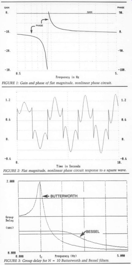
FIGURE 2: Flat magnitude, nonlinear phase circuit response to a square wave.
FIGURE 3: Group delay for N = 10 Butterworth and Bessel filters.
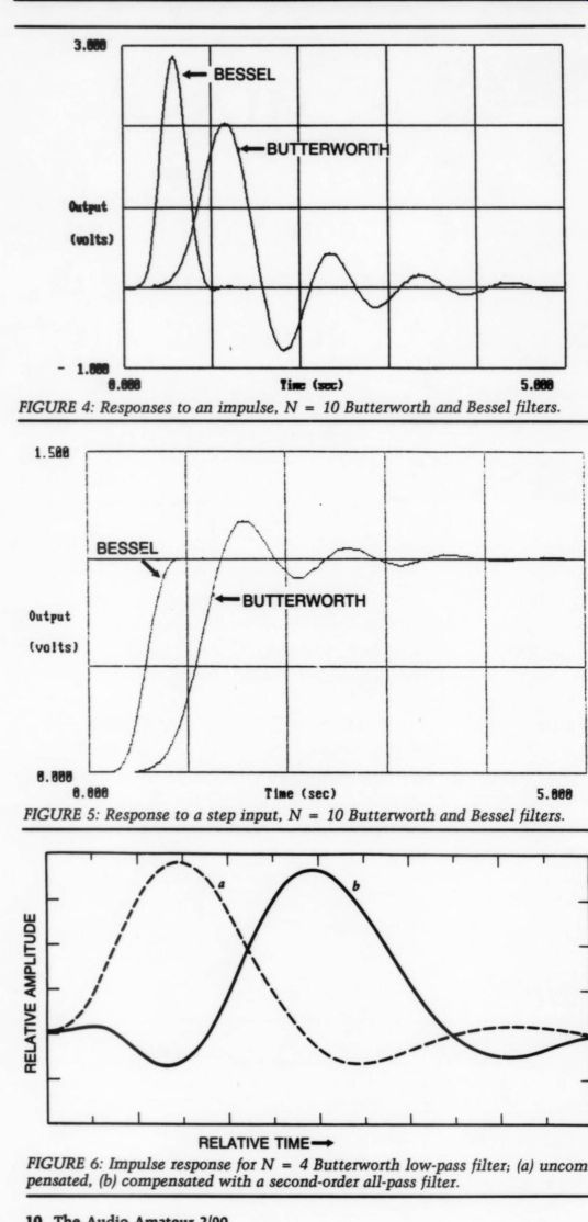
FIGURE 4: Responses to an impulse, N = 10 Butterworth and Bessel filters.
FIGURE 5: Response to a step input, N = 10 Butterworth and Bessel filters.
FIGURE 6: Impulse response for N = 4 Butterworth low-pass filter; (a) uncompensated, (b) compensated with a second-order all-pass filter.
How a system responds to an impulse is a good barometer of its phase characteristics. Theoretically, an impulse contains all frequencies with equal amplitude.
Figure 4 shows responses to an impulse for tenth-order Butterworth and Bessel filters. Figure 5 shows the response for a step input. As you can see, the Bessel filter is a much better “behaved" system than the Butterworth.
The trade-off for this well-behaved response is a gradual amplitude rolloff at the cutoff frequency. We could compare the advantages and disadvantages of different filter classes until the ideal speaker is built. I decided to use a seventh-order 0.05° equi-ripple linear phase filter for this application.
Passive Ladders
The filter I chose has an attenuation of approximately 75dB at 176kHz and 67dB at 156kHz. I chose the slight phase ripple over a maximally flat phase response for two reasons. This filter has slightly more stopband attenuation and the phase linearity is increased significantly from about two to three times the cutoff frequency. Higher order filters will have more stopband attenuation, but there comes a point where the additional circuitry might actually be degrading the performance of the system. Where this point occurs is sometimes an intuitive, rather than a technical choice.
You might be concerned about using this seventh-order filter in a CD player.
If the digital filter compensates for the gradual round off near the cutoff of a third-order Bessel filter, as the Magnavox player does, won't this seventh order filter need different equalization? Fortunately, the same equalization can be used. The rolloff difference between a third- and seventh-order Bessel filter (in the passband) is negligible.
Another question-if the phase response is so important, why hasn't the anti-aliasing filter's nonlinearity been compensated for in the smoothing filter? The answer to this is four-part:
1. The exact phase response of the anti-aliasing filter must be known before any sort of compensation can be designed
2. The compensation networks do not work well. Figure 6 shows the impulse response of a fourth-order Butter worth and a response that was equalized with a second-order all-pass filter for a least-squares approximation to a constant passband delay. This second-order equalizer does not make a significant improvement and doubles phase shift
3. For significant improvement, a complex equalizing network might introduce many distortions of its own, as a result of its nonideal components
4. A different analog-to-digital technique that averages a low resolution converter at high rates (delta sigma converters) does not have this nonlinear phase problem in the audio passband. I believe this will be the future trend.
The filter circuit I chose is a Frequency Dependent Negative Resistor (FDNR) configuration. FDNR filters have many advantages over other types, such as no active components in the signal path, low sensitivity, low noise, and a large library of existing tables. Some disadvantages are that these filters have more parts than minimum component types and, other than standard filters, are difficult to design.
X, =jwL
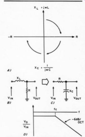
FIGURE 7: (a) real and imaginary impedances, divided by jw or rotated 90°, (b) inductor resistor low-pass filter, (c) resistor capacitor low-pass filter, (d) the response of (b) or (c).
FDNR filters are derived from the passive RLC ladder networks. The passive ladder networks are the least sensitive filter configuration, which is why the FDNR filters are so insensitive. In the transformation from passive to FDNR, inductors in the passive circuit become resistors, resistors become capacitors, and capacitors become a negative resistive term whose value depends on the square of frequency. Figure 7a shows this transformation.
A simple example can justify this transformation. Consider the LR circuit's (Fig. 7b) low-pass filter response- the series inductive reactance increases with increasing frequency. If we divide both components by jw, the resulting circuit (Fig. 7c), although different, has the same Vy,;/V,, characteristics of Fig. 7d.
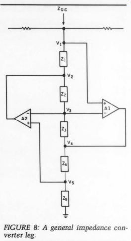
This negative real term or “D” term can be made from a general impedance converter (GIC) network (Fig. 8). The impedance of this circuit is Zge = (Z1) (Z3)(Z5)/(Z2)(Z4). The derivation of this Zc is actually not that difficult. If we assume ideal components, V3 must equal V1 because of the negative feed back of amplifier Al, and V3 must equal V5 because of amplifier A2. Therefore V1 = V3 = V5, and with a couple pages of algebraic manipulation, Z,- will fall out.
The 0.05° equi-ripple linear phase filter to be used is designed by obtaining the normalized RLC values from tables, making the transformation, and executing classical impedance and frequency scaling. The FDNR leg is accomplished by allowing Z1 and Z5 to be capacitive, and Z2, Z3, and Z4 to be resistive. If R2 =R3 then Zg =1/[(2 pi x f)^2 (C)^2 x R4|, which must equal the calculated value for that leg.
Figure 9 is the schematic of the filter.
I chose the doubly terminated filter be cause the series resistor, when trans formed, becomes a series capacitor that will block any DC level from the out put of the current-to-voltage converter.
Just as any loading will affect the nominal magnitude and phase characteristic in a passive filter circuit, so it will in the FDNR circuit.
Building a Smoothing Filter
The output buffering circuit is newly designed by Walt Jung and Rich Markell. The JFETs provide high input impedance and the LT1010, with use of the biasing pin, can be adjusted for a very linear response without the use of global feedback. I did not round off the resistors' values to the nearest standard values in the filter's GIC legs, in case you use two resistors. A method that works well is to measure the value of the resistor that is approximately 20% higher than the exact value. Then calculate a parallel resistance by subtracting the reciprocals of the larger resistor value and the exact resistor value; the reciprocal of this difference is the parallel value needed (a programmable calculator is a big help):
Rp =1/[(1/Rgxact) - (1/Rzpu)]
The parallel resistors can usually be within about 0.5% of the exact value.
The series signal path is all passive, with a capacitor and the active GIC shunted (Fig. 9). In this way the GIC leg is not in the series signal path so the demands on the op amps are less critical. Let me give you an example of how insensitive this topology can be. In a fifth-order filter, which has two GIC legs, I have seen the first stage in oscillation, completely unstable. The out put, with the exception of a gradual cutoff and attenuation, did not look that bad.
I ran a computer simulation using 1% components and an open-loop gain ...
--------------
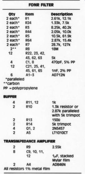
PARTS LIST
FDNR FILTER
Qty Item 2 each* 2 each* R24 2each* R3 2 each* R44 2 each* RS 2 each* R64 2 each* R7 a R8 12 R22, 23, 42, 43, 62, 63 5k 4 C1,8 470pF, 5% PP 12 C21, 25, 21, 45, 61, 65 6 A1-3
*paralleled
**carbon
=polypropylene
Description
261k, 12.1k 1.33k, 7.5K 8.25k, 40.2k 2.05k, 10.0k 10.5k, 61.9k 2.87k, 15.4k 28.7k, 127k 18M nF, 2% PP AD712N R11, 12 1k R10 1.3k resistor or 2.87k paralleled with 5k trimpot R13 1500 R*4 5k trimpot
2 2N5457 AS LT1010CT 2 R9 2.55k 8 C9, 10, 11, 12 1uF, stacked Mylar film 2 Ad AD846N All resistors 1% metal film
--------------------
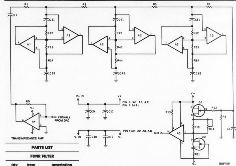
FIGURE 9: N = 7, 0.05°, doubly terminated linear phase FDNR low-pass filter. Note: If Ad is located on the motherboard, then omit A4 from this filter board and connect A4 pin 6 on the motherboard to A4 pin 6 on the filter board and A4 pin 3 on the motherboard to A4 pin 3 on the filter board.
... variation of +25%. A Monte Carlo analysis showed that 99.7% of all filters built will be within approximately 0.5° of the nominal value. Considering this filter has 630° of phase shift, you can appreciate this insensitivity.
The 18M-ohm resistor R8 provides first order high-pass filtering at low frequencies to block the DC component of the DAC and I/V. Adding this resistor can be looked at two ways. At low frequencies the GIC legs are high impedance and therefore can be neglected. The remaining circuitry can be reduced to the network shown in Fig. 10a, and the response contains a high-pass characteristic. Second, since inductors in the passive network transform to resistors in the FDNR circuit, we have added a huge inductor to the passive circuit.
The simplified network (at low frequencies) is shown in Fig. 10b. Again, the network's response is of a high-pass filter.
Figure 11a is the response to a 5kHz square wave. Up to the seventh harmonic (35kHz) is passed without significant attenuation and up to the fifteenth harmonic (75kHz) exhibits a linear phase response with respect to frequency. Figure 11b is a simulation of a ninth-order Butterworth low-pass filter that can be used for comparison.
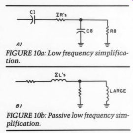
FIGURE 10a: Low frequency simplification.
FIGURE 10b: Passive low frequency simplification.
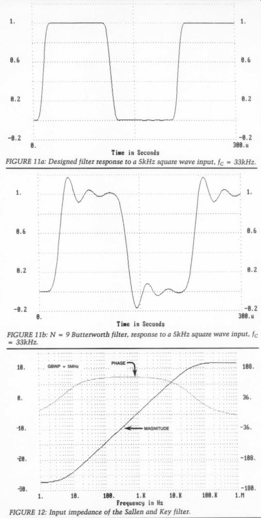
FIGURE 11a: Designed filter response to a 5kHz square wave input, fo = 33kHz.
FIGURE 11b: N = 9 Butterworth filter, response to a 5kHz square wave input, f
FIGURE 12: Input impedance of the Sallen and Key filter.
Quality components should be used throughout--see the parts list. This completes the design of the smoothing filter. Next, let's look at the current-to voltage converter. Surprisingly (well, maybe not) much improvement can be gained here, also.
The current-to-voltage converter is necessary because the output of the DAC is a current source looking to be terminated into 00. This is presently accomplished by a “virtual ground" in the first stage of the Sallen and Key filter. Figure 12 shows this filter's actual input impedance' and how it varies virtually over the entire passband (pun intended). The maximum voltage the output of the DAC should develop is 10mV by specification. At the rated rs go this calculates to 2.50 1).
Frequencies above 7kHz exceed this specification, which is a function not only of frequency but also of amplitude.
The high frequency components inherent in the stepped format of the DAC output only compound this problem. I doubt that this is a “pass-fail” specification and that some type of proportional degradation with respect to amplitude and frequency is occurring.
Again we find a section of the analog circuitry that appears to need help. A good circuit choice for this current-to voltage conversion is a transimpedance amplifier whose function, by definition, is current-to-voltage conversion. These amplifiers have very fast slew rates, on the order of hundreds of volts per microsecond, fast settling times, very high 'gains' (V/A), and a bandwidth that is almost independent of the closed-loop gain.
The transimpedance amplifier circuit has a gain of 2.55V/mA. The device, an AD846, has a slew rate of 400V/ usec and can settle from a 10V step to 0.01% in 0.11 usec. For our sample period of 23 usec, this device can settle to 0.01% (or better than 13 bits) in half of 1% of the total sampling time.
Construction
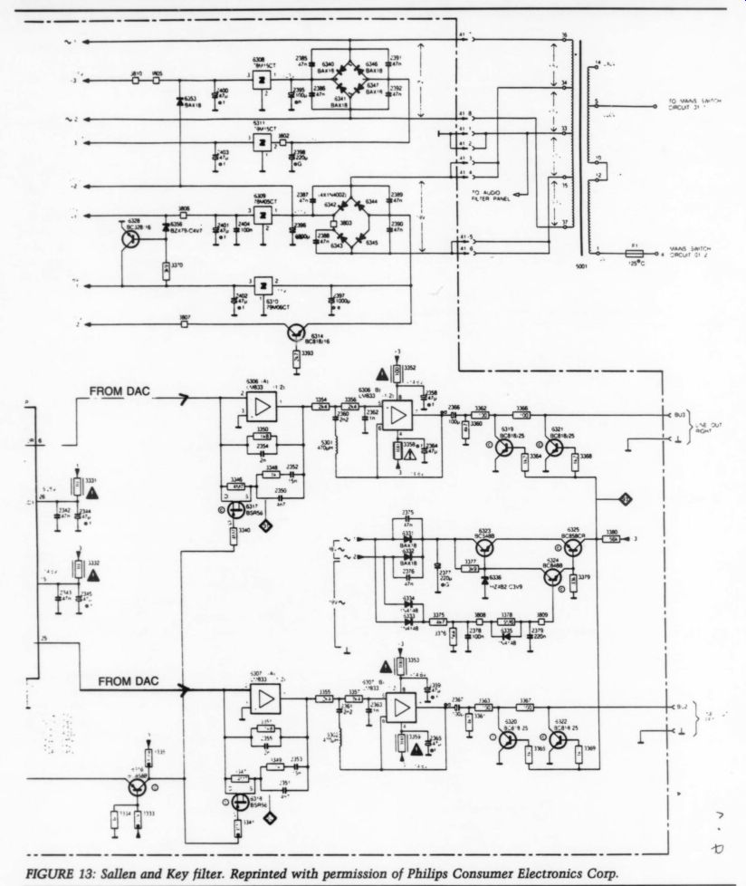
The modification I describe is applicable to the Magnavox model 560 CD player, but you can apply it to other Magnavox models and other players, as well as DAT recorders/players. First, you should make some POOGE-4 type changes. These include removing the power supply decoupling resistors 3352, 3353, 3358, and 3359; replacing the 14 DAC capacitors 2328-2341 with a 1uF stacked film type; and replacing the You can replace the dual op amps power supply filter capacitors and the 6306 and 6307 with the transimpedance amplifier with minor changes.
--------------- Fig. 13
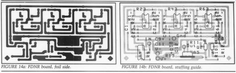
FIGURE 14a: FDNR board, foil side.
FIGURE 14b: FDNR board, stuffing guide.
DAC bypass capacitors with higher value, low ESR types (see Fig. 13 and First, short pins 7 to 8 and connect pins the parts list). 1 to 6 with a short jumper. Cut the cir cuit board foil leading to pin 7. Pins 1 and 8 should not be connected (bent up) when the transimpedance amplifier is inserted. Change the feedback resistor 3350/3351 to 2.55 k-ohm and remove the parallel capacitor 2354/2355.
The pre emphasis circuit must be removed, along with the second stage of the Sallen and Key filter. This includes resistors 3346-3349, capacitors 2350-2353, and FETS 6317 and 6318 for the pre-emphasis circuit; and resistors 3354-3357, 3360-3369, capacitors 2360-2367, transistors 6319-6322 and inductors 5301 and 5302 in the Sallen and Key filter.
You must build the FDNR filter on a separate board. A total of 11 connections to the mother board are necessary, three for power and four sets of twisted pairs for the two channels' in puts and outputs. Pick off power any where near the regulators. Solder the inputs to the filter directly to pin 6 of the transimpedance amplifier and the outputs from the buffer directly to the RCA jacks. To be safe, you should also cut the circuit traces leading to the RCA jacks.
So how does it sound, and how does it compare to an unmodified player? To be honest, I had to buy a CD player to make this modification. I'm not anti digital, but the first generation players did nothing for me. I'm sure being an analog designer doesn't help my biases, either. But CD players have come a long way since the first generation.
Digital techniques and circuitry have improved significantly, whereas the analog section has been relatively un changed.
I have addressed two problems that can be, or are, significant in CD players, both in sampling theory and in the analog circuitry. I believe this analog design can compete with any machine on the market-whatever that is worth.
This does not imply that further improvements are not possible, far from it.
Improvements allow clearer sight for other imperfections. The power supply is an obvious area for redesign, as perhaps is some additional tweaking in the smoothing filter's magnitude and phase response.
As for the sound (again), let's not get smothered in adjectives-it sounds good, very good, to me. Good listening.
ACKNOWLEDGMENTS
I thank Walt Jung and Herman Blinchikoff for allowing me to tap into their wealth of knowledge and experience, and my wife, Mary Anne, who has taken not only a musical, but technical interest in this project.
REFERENCES
1. "Error Analysis in Sampling Theory," A. Papoulis, IEEE, July, 1966.
2. Mechanical effects are many times a source of the problems here, such as servo alignment and focusing or vibration.
3. Actually, a system that has an abrupt magnitude change with a perfectly linear phase characteristic will also exhibit over shoots and ringing when an impulse is applied because of its magnitude response.
4. This is why you can hear a "spike" in your woofer, midrange and tweeter.
5. For an op amp with a 5 MHz gain band width product.
6. The high speed of the transimpedance amplifier makes it a good candidate for in stability when capacitive feedback is used. As of this writing, no good substitution has been designed for the pre-emphasis circuit.
++++++++++++++++
Also see: