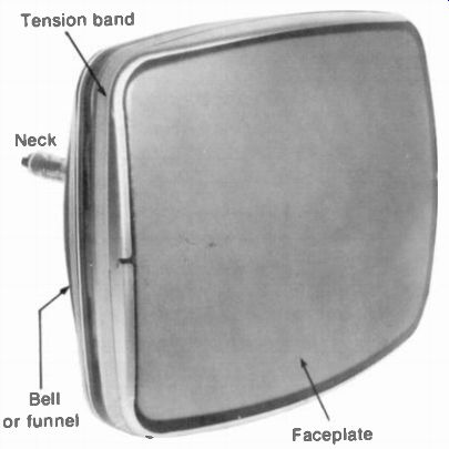
As shown in Fig. 10-1, the picture tube is a cathode-ray tube (CRT) consisting of an electron gun and phosphor screen inside the evacuated glass envelope. The narrow neck contains the electron gun to produce a beam of electrons. The beam is accelerated to the screen by positive anode voltage. The anode is a conductive coating on the inside surface of the wide glass bell. To form the screen, the inside of the faceplate is coated with a luminescent material that produces light when excited by electrons in the beam. A monochrome picture tube has one electron gun and a continuous phosphor coating that produces a picture in black and white. For color picture tubes, the screen is formed with dot trios or vertical lines of red, green, and blue phosphors. There are three electron beams, one for each color phosphor. More details are described in the following topics:
10-1 Types of picture tubes
10-2 Deflection, focusing, and centering
10-3 Screen phosphors
10-4 The electron beam
10-5 Electrostatic focusing
10-6 Magnetic deflection
10-7 Color picture tubes
10-8 Picture tubes with in-line beams
10-9 Grid-cathode voltage on the picture tube
10-10 Picture tube precautions
10-11 Picture tube troubles
FIGURE 10-1 COLOR PICTURE TUBE, TYPE NUMBER 25UP22 (RCA)
10-1 Types of Picture Tubes
If we take the type number 25UP22 as an example, 25 in. is the diagonal of its rectangular screen, within V, in. If the dimension falls exactly on 0.5 in., the next larger number is used.
The letters in the middle of the type designation are assigned alphabetically, in order of registration with the EIA. The P-number at the end of the type designation specifies the phosphor screen. This is P4 for all black-and-white picture tubes. For color, the number is P22 for all tubes with red, green, and blue phosphors.
Many picture tubes have the letter "V" just after the screen size, as in 18VBKP22. The V is for viewing dimensions. Without a V, the screen size is the outside glass diagonal. With a V, the diagonal indicates the minimum viewing area of the screen itself. In this case, the glass faceplate may be little larger than the nominal screen size.
Heater voltage. This voltage is not specified by the type number, […] . A few picture tubes for battery operation use 2 to 4 v. The heater c ihirmainiu aeneralLv mP\ for monochrome tubes with one electron gun. For color tube typical • ratinsis_are,00 to 1,1300 mA %Vil la. Although there are three electron guns, the heaters are parallel internally to provide just one pair of pins for the heater voltage. The two end pins on the base connections are usually for the heater.
Anode voltage. The anode is a conductive graphite coating, generally called aquadag, on the inside glass wall. This coating on the wide bell extends from the faceplate about halfway into the narrow neck. As a result, the electric field of the accelerating potential is symmetrical around the electron beam. Typical values of anode voltage are 18 kV for a 19-in, mono chrome tube and 25 kV for a color tube. More high voltage is needed for the same brightness with color tubes because of losses through the aperture mesh used with a three-color screen. The anode current, which is the load for the high-voltage power supply, is typically 0.6 mA for a monochrome picture tube and 1.8 mA for a color tube with three guns.
A separate anode connection is provided at the top or side of the glass bell. The connection is through a recessed cavity of about 1 /4 in. diameter. Into this fits a metal ball or spring clip with a wire from the high-voltage rectifier to contact the anode coating on the inside wall.
When installing a picture tube, put the anode connection at the same side as the high-voltage cage on the chassis.
External wall coating. Picture tubes also have a graphite coating on the outside surface of the glass bell. The external coating must be connected to chassis ground. Usually, a grounded wire spring on the mounting for the picture tube brushes against the outside coating.
High-voltage filter capacitance. The grounded coating on the picture tube provides a filter capacitance for the high voltage on the anode.
The external coating is one conductor; the anode coating is the other conductor, with the glass bulb serving as the insulator between the two. This filter capacitance is about 2,000 pF. The capacitance can hold its charge for a long time after the anode voltage is turned off.
Before handling a picture tube, therefore, make sure the high voltage is discharged by shorting the anode button to the grounded wall coating.
Input capacitance. This is C_in for video signal applied to the electron gun, either at the control grid or at the cathode. Usually, the video signal is applied to the cathode, with about 5 pF for C_in.
Faceplate. Approximately 1/2-in, thickness provides the strength required for the large faceplate to withstand the air pressure on the vacuumed glass envelope. There is also a safety-glass window. This window was separate in older receivers, but most picture tubes now have a protective glass panel sealed to the faceplate. The panel is usually made of a dark tint glass to improve picture contrast.
Deflection angle. This is the maximum angle the beam can be deflected without striking the side of the bulb. Typical values of deflection angle are 70, 90, 110, and 114°. The deflection angle is the total angle. For instance, a deflection angle of 110° means the electron beam can be deflected 55° from center. The angle for the picture tube specifies the deflection angle for the deflection yoke.
The advantage of a larger deflection angle is that the picture tube is shorter. Then it can be installed in a smaller cabinet. However, a larger deflection angle requires more power from the deflection circuits. For this reason, these tubes have a narrow neck to put the deflection yoke closer to the electron beam. A deflection yoke for a 110° tube has a hole diameter of 1 1/8 in., compared with 1 7/16 in. for tubes with a smaller deflection angle.
Different screen sizes can be filled with the same deflection angle. For instance, a 90° yoke will fill the screen of 17-, 19-, or 21-in. picture tubes if they all have the same deflection angle of 90°. The reason is that bigger tubes with the same deflection angle are longer.
10-2 Deflection, Focusing, and Centering
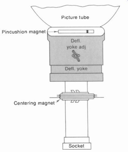
FIGURE 10-2 PLACEMENT OF DEFLECTION YOKE AND CENTERING MAGNETS ON MONOCHROME
PICTURE TUBE.
Either electrostatic or electromagnetic deflection can be used for a cathode-ray tube. For electrostatic deflection, two pairs of metal deflection plates are attached to the gun structure within the tube. Sawtooth voltage applied across each pair of plates provides an electric field to deflect the beam. This method is generally used in oscilloscope tubes, with anode voltage of 5 kV or less. However, picture tubes with anode voltage of 15 kV or more would require too much sawtooth deflection voltage. In addition, the relatively small angle for electrostatic deflection would result in a picture tube that is too long.
Picture tubes use magnetic deflection, therefore, with two pairs of deflection coils in the yoke housing on the neck of the picture tube. The associated magnetic field of sawtooth current in the deflection coils moves the electron beam horizontally and vertically to scan the raster.
Deflection yoke adjustment. In Fig. 10-2 note that the yoke is placed forward on the neck of the picture tube, against the wide bell of the envelope. If the yoke is too far back, the beam will hit the sides of the envelope for large deflection angles. The result, then, is a dark or shadowed corner on the screen. All four corners may be shadowed, especially with 1100 yokes, producing a round raster.
The entire yoke can be turned in its housing, by loosening the wing nut at the top. Turning the yoke left or right tilts the raster. Adjust for a raster with edges parallel to the screen, or else the picture will be tilted. For color tubes with three electron guns, one yoke is used to deflect all three beams.
Focus adjustment. The electron beam must be focused to a small spot of light on the screen.
Usually, focus is sharpest in the center area.
Older picture tubes used magnetic focusing, with a focus magnet on the neck behind the deflection yoke. Now, though, practically all tubes use electrostatic focus. In this method, voltage applied to the focusing electrode of the electron gun controls beam focus.
For monochrome picture tubes, the focusing grid has about 0 to 300 V. There is usually no focus control, as this focusing voltage is not critical. However, there may be a terminal board with connections for different focusing voltages.
In color picture tubes the focus grids of the three guns are connected internally, for one focusing voltage. This is usually one-fifth the anode voltage. For instance, with 25 kV for the anode, the focusing voltage would be 5 kV. This focusing voltage is usually variable. Adjust the focus control for sharp scanning lines in the raster and fine details in the picture.
Centering adjustments. Electrical centering can be done by supplying direct current through the horizontal and vertical deflection coils. Then two rheostats on the chassis serve as horizontal and vertical centering controls. This method is not used often, however, because of the added current drain on the low-voltage power supply.
Monochrome picture tubes usually have a pair of permanent magnet rings for centering, as shown in Fig. 10-2. When the tabs are together, the magnetic poles are opposing. Then there is no field to displace the beam. Spreading the tabs apart increases the field strength. Then rotating the assembly of both rings can move the beam horizontally, vertically, or at an angle, by the amount needed for centering.
Most color receivers do not have any centering adjustments. Actually, the purity ring magnet does essentially the same thing, as the three beams of the tri-gun picture tube are centered properly when the purity or beam-landing adjustment is correct.
Beam-bender magnet. See Fig. 10-3. This small permanent magnet is clamped around the neck on older monochrome picture tubes, near the base. The magnet is used with tubes that have a bent gun, which aims the electron beam to the side. Then the magnet is positioned to deflect the beam back to the screen. Adjust exactly for maximum brightness, or there will be no raster at all. The purpose of this arrangement is to prevent ions in the electron beam from striking the center of the screen where they can produce a brown burned area called ion spot.
That is why the beam bender is also called an ion-trap magnet. However, all picture tubes now have an aluminized screen, which prevents ions from reaching the screen. As a result, the ion trap magnet is not used anymore.
-------------------
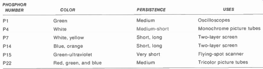
TABLE 10-1 TYPICAL SCREEN PHOSPHORS FOR CATHODE-RAY TUBES PHOSPHOR
NUMBER COLOR PERSISTENCE USES
P1 Green P4 White P7 White, yellow P14 Blue, orange
P15 Green-ultraviolet
P22 Red, green, and blue Medium Medium-short Short, long Short, long Very short Medium Oscilloscopes
Monochrome picture tubes Two-layer screen Two-layer screen Flying-spot scanner Tricolor picture tubes
--------------------
10-3 Screen Phosphors
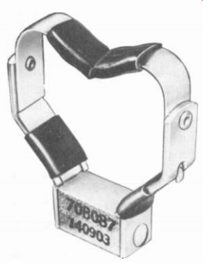
FIGURE 10-3 ION-TRAP MAGNET. USED ON OLDER MONOCHROME PICTURE TUBES.
Most common are the P1 green phosphor for oscilloscope tubes, the P4 white phosphor for monochrome picture tubes, and the P22 phosphor for color tubes. These are listed in Table 10-1, along with other phosphors for cathode ray tubes. The missing P-numbers have similar uses, but some types are obsolete.
The phosphor chemicals are generally light metals such as zinc and cadmium in the form of sulfide, sulfate, and phosphate compounds. For the green P1 phosphor, a form of zinc silicate called willemite is generally used.
The P4 white phosphor usually combines compounds of zinc sulfide, cadmium sulfide, or zinc silicate. This phosphor is actually a combination of yellow and blue, as no one phosphor can produce white. For color screens, the P22 phosphor includes zinc sulfide for blue, zinc silicate for green, and special rare-earth elements such as europium and yttrium for red.
The phosphor material is processed to produce very fine particles which are then applied to the inside of the glass faceplate. This very thin coating to form the screen is a uniform layer for monochrome tubes. For color tubes, though, the phosphor is deposited in dots or vertical lines for each color. You can see the individual color dots or lines with a small, portable microscope of 50x power against the screen while the picture is on. The spaces around the color dots or lines are usually made black to improve contrast.
In terms of molecular structure, the phosphors are crystals where an activator material such as manganese or silver can be added to distort the crystal lattice. Then high-velocity electrons excite the phosphor to emit light.
Electrons within atoms of the phosphor are forced to move to a higher energy level. As these electrons fall back to a lower level, energy is radiated. Radiation of light from the screen as it is excited by the electron beam is luminescence. When the light is extinguished after excitation, the screen is fluorescent. Phosphorescence is continued emission of light after excitation.
Screen persistence. This can be defined as the time for light emitted from the screen to decay to 1 percent of its maximum value. Medium persistence is desirable to increase the average brightness and to reduce flicker. However, the persistence must be less than 1/30 s for picture tubes so that one frame does not persist into the next and cause blurring of objects in motion.
The decay time for picture tubes is approximately 0.005 s, or 5 ms, which is a medium-short persistence. The P1 green phosphor for oscilloscope tubes has a longer persistence of 0.05s.
Aluminized screen. Practically all picture tubes now have a very thin coating of aluminum on the back surface of the screen phosphor.
With anode voltage of 10 kV or more, the electrons in the beam have enough velocity to pass through the aluminum and excite the phosphor.
There are several advantages. First, the metal backing reflects light from the screen out through the faceplate. Also, negative ions in the beam cannot penetrate the aluminum coating because the heavy ions do not have enough velocity. An ion-trap magnet is not necessary, therefore, with an aluminized screen. Finally, the aluminum coating is connected to the anode wall coating inside the tube. As a result, the full anode voltage is applied to the screen phosphor.
The first step in applying the aluminum coating is to spray a thin plastic film over the en tire screen area. This film prevents aluminum molecules from penetrating the phosphor material. After the plastic film has dried thoroughly, a rod of pure aluminum is evaporated near the screen in a vacuum. The aluminum vapor then condenses on the screen surface to form the aluminized coating. The plastic film is removed later in a baking-out process.
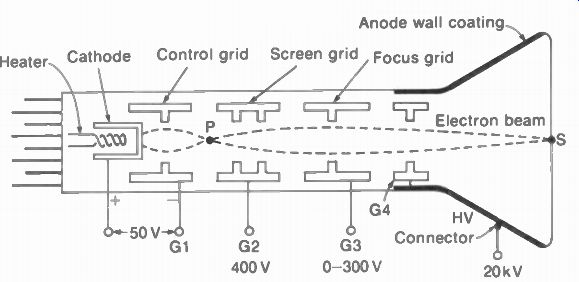
FIGURE 10-4 ELEMENTS OF AN ELECTRON GUN WITH LOW-VOLTAGE ELECTROSTATIC FOCUSING.
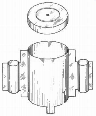
FIGURE 10-5 CONTROL-GRID CYLINDER WITH APERTURE DISK. DIAMETER IS V, IN
10-4 The Electron Beam
The electron gun in Fig. 10-4 includes a heater, cathode, control grid G1, screen grid or accelerator G2, and focusing grid G3. Each grid structure is a metal cylinder with a small aperture or hole in the center. Figure 10-5 shows a control grid cylinder and disk cover with an aperture of 0.04 in. The electrodes are generally made of nickel or a nickel alloy, mounted on ceramic insulator supports inside the glass neck of the cathode-ray tube.
The control grid G1 has a negative bias with respect to cathode, in order to control the space charge of electrons from the heated cathode. The succeeding grids have positive potentials, with the anode at the highest voltage to accelerate the electron beam to the screen.
Note that the accelerating grid G4 is connected internally to the anode. This is accomplished by spring clips that contact the inside wall coating.
Most of the electrons go through the apertures and are not collected by the positive electrodes because their circular structure provides a sym metrical accelerating field around all sides of the beam.
The electron beam has a complete circuit for current because of secondary emission from the screen. These secondary electrons are collected by the aluminum backing, which is connected to the anode. The path for electron flow is from cathode to the screen to the anode and returning to cathode through the high-voltage supply. A typical value of beam current for one gun is 0.6 mA with 20-kV anode voltage.
10-5 Electrostatic Focusing
Electrons emitted from the cathode tend to di verge because they repel each other. However, the electrons can be forced to converge to a point by an electric or magnetic field. This action is similar to focusing a beam of light by optical lenses. Therefore, the term "focusing" is used for producing a narrow beam, while the focusing system is an electron lens. Two electron lenses are used. The first is the electrostatic field between cathode and control grid produced by their difference in potential. This voltage focuses the beam to a spot called the crossover point, just beyond the control grid.
The second lens may be either an electrostatic field or a magnetic field, to focus the beam just before deflection. As a result of the two electron lenses, the beam is focused to a small sharp spot of light on the screen.
Crossover point. Details of the first electron lens formed by the electrostatic field between cathode and control grid are illustrated in Fig. 10-6. The lines of force in a are shown tending to repel electrons back to the cathode because the control grid is negative. The lines are straight where the cathode and grid are parallel.
Such straight lines indicate a uniform change of potential in the space between grid and cathode.
However, where the grid does not have uniform distances to the cathode, the lines of force curve. Notice that the curved lines of force have the direction that repels electrons toward the center axis. Electrons diverging the most have the greatest force toward the center.
Remember now that the positive G2 voltage and anode voltage provide a forward accelerating force. The net result is that diverging paths are bent so that the electrons go through the grid aperture (Fig. 10-6b). The diverging beam then is focused at point P just beyond the control grid. Note that electrons emitted in the direction KA are made to follow the curved path KDP. Similarly, electrons from path KB are forced into path KEP. Electrons in a straight path along the center axis stay in this line.
Any voltage has an associated electric field, just as any current has an associated magnetic field. When the voltage has a steady value, its field is electrostatic, meaning that it does not vary with respect to time.
The focal point P is the crossover point produced by the first electron lens. P serves as a point source of electrons to be imaged onto the screen by the second electron lens for a sharp spot. Fine focus can be produced this way because the crossover point is much smaller than the cathode area supplying electrons for the beam.
Low-voltage focusing. The focusing grid, which is usually G3, has 0 to 300 V. This is shown in Fig. 10-4. The electron beam is focused because of deceleration when the G3 voltage is less than the G2 voltage. Most mono chrome picture tubes use this method.
High-voltage focusing. The voltage for the focusing grid is generally about one-fifth the anode voltage. For instance, the focusing is 5 kV with 25 kV on the anode. In this type of electron gun, the anode voltage is connected internally to an accelerating grid before the focusing grid. Then the electron beam is decelerated in passing through the electrostatic field between the two grids. Color picture tubes use this method. Generally, there is a control to vary the focus voltage for the sharpest scanning lines and small details in the picture.
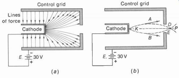
FIGURE 10-6 ELECTROSTATIC FO CUSING BY DECELERATION OF ELEC TRONS IN THE
BEAM. (a) ELECTRIC LINES OF FORCE BETWEEN CONTROL GRID AND CATHODE. ELECTRON
BEAM NOT SHOWN. (b) DIVERGING BEAM FROM K FOCUSED AT CROSS OVER POINT P. LINES
OF FORCE NOT SHOWN.
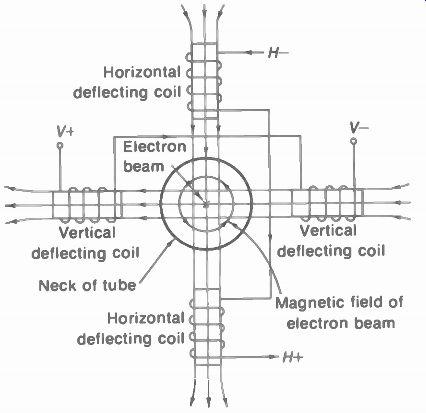
FIGURE 10-7 MAGNETIC DEFLECTION. ELECTRON BEAM WILL MOVE DOWN AND TO THE
RIGHT FOR ELECTRON FLOW SHOWN IN SCANNING COILS.
10-6 Magnetic Deflection
Two pairs of deflection coils are used, as illustrated in Fig. 10-7, mounted externally around the neck of the tube just before the bell. The pair of coils above and below the beam axis produce horizontal deflection; the coils left and right of the beam deflect it vertically. This perpendicular displacement results because current in each coil has a magnetic field that reacts with the magnetic field of the electron beam to produce a force that deflects the electrons at right angles to both the beam axis and the deflection field.
To analyze the deflecting action, re member that the reaction between two parallel fields always exerts a force toward the weaker field. Consider the horizontal deflection coils first in Fig. 10-7. The windings are in a horizontal plane above and below the beam axis. Using the left-hand rule, the thumb points in the direction of the field inside a coil when the fingers curve in the direction of the electron flow around the coil. Therefore, the deflection field for the horizontal windings is downward. When the direction of the electron beam is into the paper, as indicated by the cross in the center, its magnetic field has lines of force counterclockwise around the beam in the plane of the paper. To the left of the beam axis, the magnetic field of the electron beam is down in the same direction as the deflecting field, while the fields are opposing on the right. The electron beam is deflected to the right, therefore, as the resultant force moves the beam toward the weaker field.
In a similar manner, the vertical deflection coils deflect the electron beam downward. Deflecting currents for both sets of coils are applied simultaneously, deflecting the beam to the lower right corner of the screen.
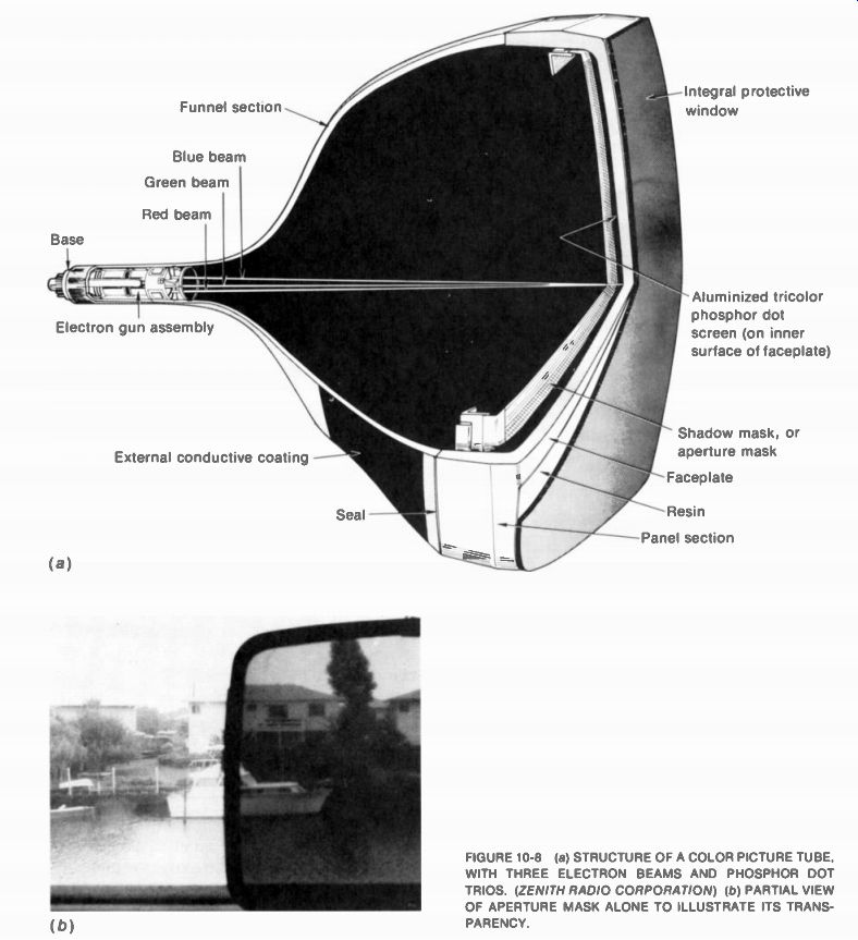
FIGURE 10-8 (a) STRUCTURE OF A COLOR PICTURE TUBE, WITH THREE ELECTRON BEAMS
AND PHOSPHOR DOT TRIOS. (ZENITH RADIO CORPORATION) (b) PARTIAL VIEW OF APERTURE
MASK ALONE TO ILLUSTRATE ITS TRANS PARENCY.
10-7 Color Picture Tubes
The screen has red, green, and blue phosphors, with three electron beams for these primary colors. See Fig. 10-8a and the aperture mask in b.
This metal plate has very small holes that allow electrons to go through and excite the phosphor dots. The mask is made of steel 0.006 in thick.
Electrons that do not have the required angle are blocked. For this reason, it is generally called a shadow mask. When the three beams converge at the correct angle, each beam excites its respective color, without straddling the other two colors in the dot trios. You do not see the individual dots because a 21-in, screen has over 450,000 trios. Similarly, the screen can have trios of red, green, and blue vertical stripes.
The screen phosphors produce the colors. All electrons are the same, and any electron beam has no color. However, each color phosphor has its own electron beam. If you operate the red gun alone, by cutting off the other two guns you will see a red raster without video signal or a red picture with signal. The color intensity increases with more beam current. Similarly, the screen can be made all green or blue by operating only one gun.
In normal operation, though, the three guns excite all three color phosphors to produce red, green, and blue on the screen. What you see is the picture in all its natural colors as the red, green, and blue components are superimposed. Just about any color can be reproduced by a mixture of these primary colors. For in stance, yellow is a combination of red and green. Furthermore, white is produced by the proper combination of red, green, and blue.
Black in the picture is just the absence of excitation when all three beams are cut off.
Figure 10-9 shows the schematic diagram of a color picture tube with three electron guns.
There are three separate cathodes and three separate control grids. Separation is necessary so that individual color signals can be coupled to the grid-cathode circuit to modulate the beam intensity. In many circuits, the Y signal goes to the three cathodes, with each color video signal to its control grid. Or, the Y signal with each color video signal goes to its cathode. In this case, the three control grids can have one common connection to chassis ground.
Each gun has a separate screen grid. This voltage is adjusted for the desired cutoff characteristic on each gun.
FIGURE 10-9 SCHEMATIC DIAGRAM OF COLOR PICTURE TUBE WITH THREE ELECTRON GUNS.
Deflection YOKE, CONVERGENCE YOKE, AND PURITY MAGNETS ARE AROUND THE NECK
OF TUBE.
The three guns have separate focus grids, but these are connected internally to one pin for a common focusing voltage. In addition, the three accelerating grids are connected internally to the anode voltage.
Also connected internally to the anode is the convergence electrode for all three guns.
This assembly has pole pieces to concentrate the magnetic field for current in the external convergence yoke. More details of the three gun assembly can be seen in Fig. 10-10.
Serving for all three guns are the deflection yoke, convergence yoke, and purity magnet mounted on the neck of the picture tube. Their functions are as follows:
1. Deflection yoke. Its vertical and horizontal coils deflect the three beams to form the scanning raster.
2. Convergence yoke. This yoke has individual adjustments for the red, green, and blue beams to make them converge through the openings in the aperture mask. For each beam, there is a small permanent magnet and coil. The three assemblies for red, green, and blue are symmetrical around the yoke frame, usually with blue at the top. The magnets are adjusted for static convergence in the center area of the screen. The coils have correction current for dynamic convergence at the top, bottom, left, and right edges of the screen.
3. Blue lateral magnet. It moves only the blue beam left or right to help in making the convergence adjustments. This permanent magnet is usually on the purity-ring assembly.
4. Purity magnet. Adjusts the three beams to produce pure red, green, and blue without any effect from the other colors. The purity adjustment is also called beam landing. The purity magnet consists of two rings, like a centering magnet, for all three guns.
How these components are mounted on the neck of the color picture tube is shown in Fig. 10-11. In addition, note the metal shield over the front section of the tube. The shield minimizes the effect of the earth's magnetic field on the electron beams in the tube.
The details of how to make the convergence and purity adjustments are explained in the next SECTION. In brief, though, the test of good convergence is a black-and-white picture without color fringing around edges of objects.
This is very noticeable with numbers and letters.
An example of poor convergence is shown in color plate II. The test of good purity is a solid red, green, or blue raster. These can then be combined for a white raster without patches of color. The lack of purity shows as the wrong colors in some parts of the picture. An example of poor purity in the raster is shown in color plate III. Electron-gun arrangements. See Fig. 10-12.
In a, the three guns are 120° apart in a circle.
This form is called a delta-gun assembly.
Because of the equal spacing, each gun can have the maximum possible size in the tube neck. However, the convergence adjustments must correct for the guns in different planes.
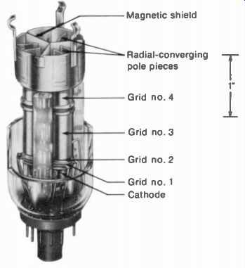
FIGURE 10-10 THREE ELECTRON GUNS IN DELTA ASSEM BLY (RCA)
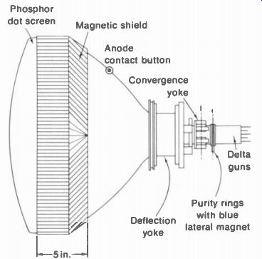
FIGURE 10-11 MAGNETIC COMPONENTS ON NECK OF COLOR PICTURE TUBE.
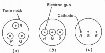
FIGURE 10-12 METHODS OF HAVING THREE ELECTRON BEAMS IN ONE PICTURE TUBE.
(a) DELTA GUNS. (b) IN LINE GUNS. (c) ONE GUN WITH THREE IN-LINE CATHODES.
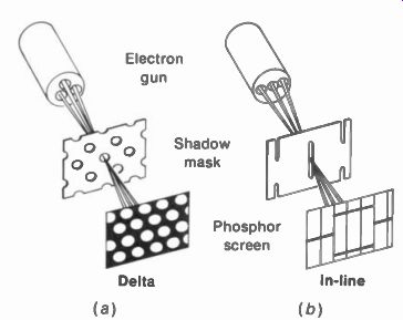
FIGURE 10-13 TWO BASIC TYPES OF COLOR PICTURE TUBES. (a) DELTA GUNS WITH
PHOSPHOR-DOT TRIOS. (b) IN-LINE BEAMS WITH SLOTTED MASK FOR VERTICAL PHOSPHOR
STRIPES.
Usually, the guns are angled in toward the center to help the convergence. In b, the three guns are in one horizontal plane, also angled in toward the center. Convergence is easier with this in-line type. Each gun must be smaller, compared with the delta guns. With a smaller gun, it is more difficult to obtain a high-intensity spot with sharp focus. In c, there are three cathodes to produce three electron beams, but all three beams are focused and accelerated as one common electron gun.
Types of color screens. When the red, green, and blue phosphors are in color dots, they form trios or triads. This color screen is often used with delta guns (Fig. 10-13a). However, the color phosphors can also be vertical stripes of red, green, and blue, with a slotted mask (Fig. 10-13b). Green is usually at the center. The striped screen is generally used with in-line guns.
With color dots, the shadow mask has holes opposite the triads. With stripes, the mask has vertical slots. In both cases, the shadow mask blocks an appreciable amount of beam current. Otherwise, correct convergence and color purity would be impossible. Typically, less than 20 percent of the beam current excites the phosphor screen. This factor is why color picture tubes need higher values of anode voltage, beam current, cathode current, and heater power, compared with monochrome tubes.
10-8 Picture Tubes with In-Line Beams
Two examples are the Sony Trinitron and RCA in-line types. These use in-line beams with vertical phosphor stripes. The GE Portacolor tube uses in-line beams with dot trios. Type numbers for these picture tubes, with their characteristics, are listed in Table 10-3 in the summary at the end of this SECTION.
The main feature of in-line guns with vertical phosphor stripes is that convergence and purity are simplified. First, all the beams are in the same plane. Then it is only necessary to adjust the outside beams left and right with respect to the center beam. Also, the vertical stripes make this type less sensitive to beam-landing errors caused by the earth's magnetic field.
Sony Trinitron picture tube. See Fig. 10-14.
There is no convergence yoke because electrostatic convergence is used. The phosphor screen of vertical stripes is illustrated in Fig. 10-15. The aperture grille is similar to a shadow mask, but instead of holes the grille has one vertical slot for each set of red, green, and blue stripes.
Green is in the center directly behind each slot.
The aperture grille increases the transparency for beam current, compared to a shadow mask, allowing more brightness.
The electron-gun assembly of the Trinitron is illustrated in Fig. 10-16. There is actually just one electron gun, but with three cathodes for the red, green, and blue beams. The control grid (G1) is a single cup with three apertures for the three beams. Video signal must be coupled to the cathodes, therefore, because they are the only separate electrodes for each color. The screen grid (G2) is common, and one focus grid is used for all three beams.
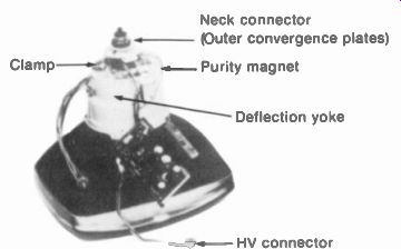
FIGURE 10-14 TRINITRON COLOR PICTURE TUBE. SCREEN DIAMETER IS 12 IN. (SONY
CORPORATION)
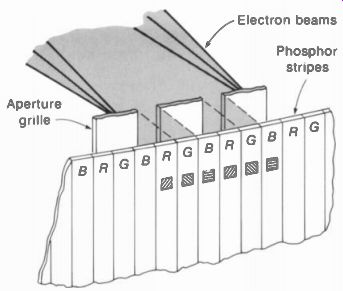
FIGURE 10-15 VERTICAL PHOSPHOR STRIPES ON SCREEN OF TRINITRON COLOR PICTURE
TUBE.
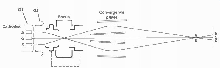
FIGURE 10-16 ELEMENTS IN THE ELECTRON GUN OF TRINITRON COLOR PICTURE TUBE.
The electrostatic convergence is accomplished by the four convergence plates shown in Fig. 10-15. The green beam passes through the center plates, while the other two beams pass between the outer plates. Both center plates are connected internally to the anode. Between the plates, though, the potential difference is zero. As a result, the green beam is not affected by convergence voltage applied to the outer plates. The red and blue beams are moved horizontally for the convergence adjustments. Dc voltage is applied for static convergence. Also, ac correction voltage can be adjusted for dynamic convergence. The voltage for the outer convergence plates is about 450V less than the anode voltage.
RCA in-line picture tube. The construction is illustrated in Fig. 10-17. Continuous vertical phosphor strips are used with in-line beams, but the aperture mask is slotted to provide a spherical shape. The few components mounted on the neck are shown in Fig. 10-18. These include the defection yoke and a magnet assembly for purity and static convergence. However, these are cemented to the tube, because their position is critical. This arrangement allows permanent factory adjustments, so that very little setup is required for a new receiver or a new picture tube. For replacement, the entire assembly of picture tube, yoke, and magnets is changed as one unit. The magnet assembly on the neck is for static convergence, as there are no adjustments for dynamic convergence.
The deflection yoke uses toroidal windings instead of a saddle yoke. A toroidal coil is made in the form of a ring magnet, to provide a strong magnetic field inside the ring.
The characteristics of type number 15VADP22, as an example, are listed in Table 10-3. This tube has a deflection angle of 90 deg and anode voltage of 25 kV for the 15-in. screen.
There are three separate cathodes, but the control grid is common. Also, the screen grid (G2) and focusing grid (G3) serve for all three guns.
10-9 Grid-Cathode Voltage on the Picture Tube
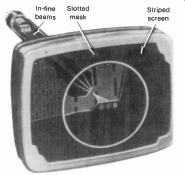
FIGURE 10-17 CONSTRUCTION OF COLOR PICTURE TUBE WITH IN-LINE GUNS AND VERTICAL
PHOSPHOR STRIPES. (RCA)
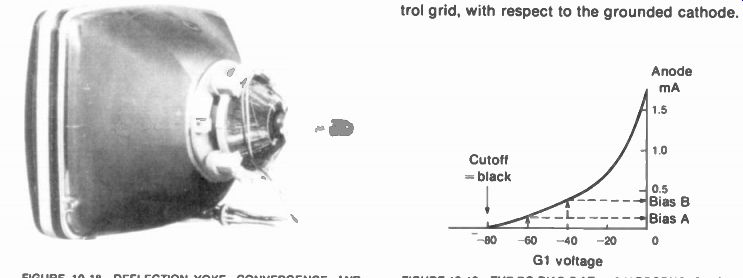
FIGURE 10-18 DEFLECTION YOKE, CONVERGENCE, AND PURITY MAGNETS ON NECK OF
PICTURE TUBE SHOWN IN FIG. 10-17.

FIGURE 10-19 THE DC BIAS BAT -40 V PRODUCES MORE BEAM CURRENT AND HIGHER
BRIGHTNESS THAN BIAS A AT -60 V.
For either monochrome or color, and for delta guns or in-line guns, the dc bias voltage between control grid and cathode of the electron gun determines the average beam current or anode current. The effect of two different bias voltages is shown in Fig. 10-19. Note that the bias value A at -60 V allows the anode current of approximately 0.1 mA. This beam current is close to cutoff, resulting in very low brightness on the screen. When the dc voltage is shifted to the bias B at -40 V, the smaller negative bias allows more anode current. This higher beam current is approximately 0.4 mA, producing higher screen brightness. In summary, then, the screen is brighter with less negative grid bias. Methods of supplying the dc bias to control the brightness are shown in Fig. 10-20. The brightness control adjusts the brightness of the raster and the picture on the raster.
Negative dc bias at the control grid. In Fig. 10-20a, the bias of -40 V is provided for the control grid, with respect to the grounded cathode.
The brightness control R, varies the bias.
Smaller negative values allow more brightness.
Higher negative bias can cut off the beam to extinguish the raster.
Positive dc bias at the cathode. In Fig. 10-20b, the bias of 40 V is positive at the cathode, with respect to the grounded grid. The brightness control R, operates the same way as in a but with cathode bias. Less positive cathode bias allows more beam current for higher brightness. In the opposite direction, when the positive cathode bias is increased to cutoff, there is no beam current and the screen is black. The raster can be extinguished by cutoff bias whether the cathode is positive or the grid is negative. Actually, cathode bias is generally used for picture tubes, rather than grid bias.
It is the difference in potential between cathode and grid that determines the beam current. An example is illustrated in Fig. 10-20c.
Here, both the cathode and grid are positive.
The cathode is at 160 V and the grid at 120 V, but these voltages are with respect to chassis ground. The grid is less positive, which makes it negative with respect to cathode. Specifically, for the voltages shown, the potential difference is 160 - 120 = 40 V at the cathode with respect to the grid.
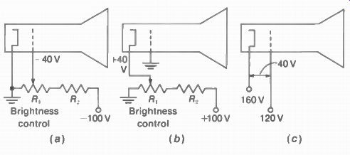
FIGURE 10-20 METHODS OF DC BIAS FOR GRID-CATHODE CIRCUIT OF PICTURE TUBE.
(a) NEGATIVE GRID BIAS OF -40 V (b) POSITIVE CATHODE BIAS OF 40 V (c) POTENTIAL
DIF FERENCE OF 40 V
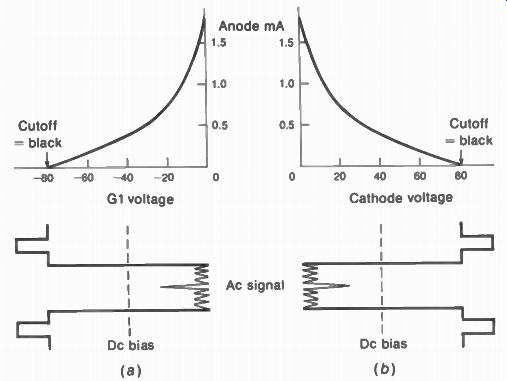
FIGURE 10-21 HOW AC VIDEO SIGNAL VARIES BEAM CURRENT TO RE PRODUCE THE PICTURE
Information (a) NEGATIVE SYNC AND POSITIVE WHITE AT CONTROL GRID. (b) POSITIVE
SYNC AND NEGATIVE WHITE AT CATHODE.
Brightness control for the picture tube. In monochrome receivers, the brightness usually is set by varying the cathode bias on the picture tube, as in Fig. 10-20b. For color tubes with three guns, however, this method would require three controls. Therefore, in color receivers the brightness control varies the dc bias on the Y video amplifier. This stage is dc coupled to the three guns of the picture tube.
How the ac video signal varies the beam intensity. The grid-cathode bias is a dc voltage that sets the brightness of the entire screen area.
Then the ac video signal voltage varies tie instantaneous values of beam intensity to reproduce the details of picture information. Figure 10-21 illustrates this idea with video signal for one horizontal line. Grid drive is shown in a, with cathode drive in b. For either method, the effect is the same as any ac signal at the control grid of a vacuum tube having a steady dc bias voltage. The bias sets the operating point, as the ac signal varies the beam current around this average level. This procedure of varying the beam current is called intensity modulation or Z axis modulation.
The peak-to-peak amplitude of the ac video signal determines the contrast in the picture, between peak white with maximum beam current and black at cutoff. The contrast control is in the video amplifier to vary its gain, which determines the amount of video signal for the picture tube. In color receivers, the red, green, and blue drive controls vary the proportion of Y luminance signal for each gun.
Grid drive. In Fig. 10-21a, the video signal for the control grid is shown with negative sync polarity. This means the blanking level drives the grid voltage more negative than the bias, to cut off the beam current for black. Specifically, the grid cutoff voltage here is -80 V. The white peaks in the video signal drive the grid voltage less negative than the bias for maximum beam current.
Cathode drive. In Fig. 10-21b, the video signal for the cathode is shown with positive sync polarity. This means the blanking level drives the cathode voltage more positive than the cathode bias to cut off the beam current.
Specifically the cathode cutoff voltage here is +80 V. The white peaks in video signal drive the cathode voltage less positive than the bias for maximum beam current. It should be noted that cathode drive is generally used for the picture tube, because it provides more contrast than grid drive for the same amount of video signal.
The transfer-characteristic curves in Fig. 10-22 illustrate how the beam current varies with video signal, for grid drive and cathode drive.
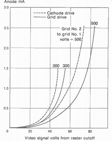
FIGURE 10-22 GRID-CATHODE DRIVE CHARACTERISTICS FOR 23CP4 PICTURE TUBE. (RCA)
10-10 Picture Tube Precautions
Since the anode voltage is usually 15 kV or more, high-voltage safety precautions should be followed to avoid electrical shock. Turn off the power before touching the picture tube. The anode capacitance should be discharged with a jumper lead to chassis ground. Connect the ground end first.
Because of its large surface area, a ture tube has a very strong force of air pressure on the glass envelope. Normal air pressure on the outside is approximately 15 lb/in^2, while the inside is a vacuum. For a 20-in, tube the surface area is about 1,000 in^2 and total force on the bulb then is 15 X 1,000 = 15,000 lb. The envelope is strong enough to withstand this force if there are no flaws and if the tube is handled gently. Do not carry the tube by its neck. If there is a crack in the glass, the external force can produce an implosion inward before the tube explodes outward. It is recommended that shatterproof safety glasses be worn when handling picture tubes for removal and installation.
X-radiation. X-rays are invisible radiation with wavelengths much shorter than visible light.
Prolonged exposure to x-rays can be harmful.
The x-rays are produced when a metal anode is bombarded by high-velocity electrons, generally with an anode voltage above 16 kV. Color receivers with an anode voltage of 18 to 25 kV can produce soft x-rays. This radiation is easier to shield than hard x-rays produced with much higher accelerating voltages up to 100 kV. Lead and leaded glass are used for shielding against x-ray penetration in general. For soft x-rays, some attenuation is provided by wood, card board, pressed paper, metals, and glass.
The main sources of x-radiation in a television receiver are the picture tube, especially from the metal shadow mask, the high-voltage rectifier tube, and the high-voltage regulator tube. However, when solid-state devices are used for the high-voltage supply and its regulation, they do not produce x-rays. Picture tubes with an improved faceplate for x-ray shielding may have the letter "V" in the type designation, or the prefix letters "XR." Television receivers are designed to limit the level of x-radiation below the value set by the U.S. Department of Health, Education, and Welfare. The limit is 0.5 milliroentgen per hour (mR/hr) as measured at a point 2 in. from any surface of the receiver. This dosage is extremely small, as it probably is less than the radiation from the face of a luminous clock.
For color picture tubes, the x-radiation is mainly a question of not allowing the high voltage to exceed the recommended value. It is required that the receiver not be able to produce a viewable picture when the high voltage exceeds a specified limit. Two methods often used are to cut off the horizontal scanning or to remove horizontal synchronization when the anode voltage gets too high. This system is called a horizontal disabling circuit.
Spark-gap protection. Because of close spacing between electrodes and the high voltages, arcing or flashover can occur in the electron gun, especially to the control grid. The arcing causes voltage surges that damage transistors.
For protection of the receiver circuits during arcing, spark gaps are used to provide a shunt path for the arc. The idea is to have the arc dissipated across the spark gap, instead of in the receiver circuits. Typical values for the gap breakdown voltage are 2 to 4 kV. Spark gaps are provided for the three control grids, the three screen grids, and possibly the focusing voltage.
Spark-gap capacitors are often used. One type looks like a flat ceramic disk capacitor but with an open slit at the top. The arc-voltage rating for these capacitors is 1.5 or 2.5 kV. This type is sometimes called a snap capacitor. At the picture tube socket, a 1,000-0 resistor may be inserted in series with each lead, except for the heater. In newer picture tubes, spark gaps are incorporated into the base and socket connections.
Dc biasing of the heater. To prevent arcing from the cathode, the heater in a color picture tube usually has a dc bias, in addition to its ac power for heating. The dc offset is about 125 V to chassis ground. This voltage raises the dc potential of the heater close to the cathode voltage.
With less potential difference, the danger of arcing is reduced.
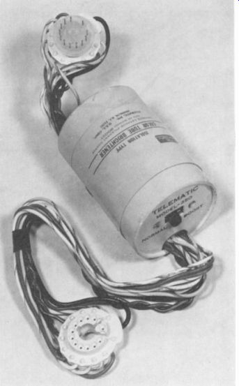
FIGURE 10-23 BRIGHTENER OR BOOSTER FOR HEATER OF PICTURE TUBE.
10-11 Picture Tube Troubles
Typical troubles are weak emission from the cathode, an open heater, or an internal short circuit, usually from grid to cathode or cathode to heater. An open heater means no emission and no brightness. You can look through the glass neck to see if the heater is lit. It is important to note, though, that the most common cause of no brightness is no anode voltage from the flyback high-voltage supply.
With weak emission, the raster and picture cannot be made bright enough. Insufficient brightness can also result from voltage troubles.
However, weak emission results in a characteristic silvery effect in white areas of the picture when you turn up the brightness. The cause is saturation limiting of the beam current emitted by the cathode. Then the details are lost in white highlights. This effect also occurs with color tubes. See color plate XIV. When only one gun is weak, it may help to rearrange the cathode leads for Y signal, to supply more drive to the weak gun.
Weak emission in old picture tubes can often be improved temporarily by using a tube brightener or filament booster (Fig. 10-23). This is just a small filament transformer to step up the heater voltage, usually from 6.3 to 7.8 V. The connections are simple, as the picture tube plug goes on the brightener and its plug on the tube.
The brightener must have the same type of socket as the picture tube, and provide for either series or parallel heater connections. Brighteners are available for monochrome or color tubes.
-----------------
Anode cap: Heater Cathode of red gun Grid No. 1 of red gun Grid No. 2 of red gun Grid No. 2 of green gun Cathode of green gun Grid No. 1 of green gun Grid No. 3 Cathode of blue gun Grid No. 1 of blue gun Grid No. 2 of blue gun Heater External conductive coating Collector (anode wall coating)
Anode (Grid No. 4, screen, collector)
(a) (b)
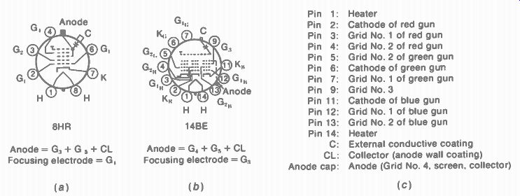
FIGURE 10-24 TYPICAL BASE-PIN CONNECTIONS FOR PICTURE TUBES. (a) 8-PIN BASE
8HR FOR MONOCHROME TUBES. (b) 14-PIN BASE 14BE FOR COLOR TUBES WITH DELTA
GUNS. (c) LISTING OF ELECTRODES FOR BASE 14BE.
----------------
When the brightener uses a transformer with a separate secondary winding, it isolates the heater of the picture tube from chassis ground. This isolation can be used to repair the trouble of a short from cathode to heater in the picture tube. The short is not eliminated, but without the heater connection to ground, there is no effect on the cathode signal.
When a picture tube is replaced, either a new or rebuilt tube can be used. Rebuilt picture tubes cost less because they use the old envelope, or "dud," but the internal parts are all new.
Continuing spot. This luminous spot remains at the center of the screen for a few seconds after the receiver is turned off. The afterglow results because anode voltage remains on the filter capacitance. This spot really does not damage the screen. However, one method of eliminating the afterglow is to turn the brightness up for maximum beam current just before you turn off the receiver. Then the high voltage can discharge quickly.
Screen burn. If a spot or line is on the screen, instead of the complete raster, the brightness should be turned down to avoid burning the screen. The burn causes a dark brown area of the phosphor that cannot produce any light.
The higher the anode voltage, the greater is the danger of the screen burn. However, it should be noted that when the receiver has a service switch to collapse the raster into a horizontal line, the brightness is automatically reduced by the switch.
Blooming. This term describes a picture that increases in size and goes completely out of focus when the brightness is increased. The blooming results from a sharp drop in the amount of high voltage with the increase in beam current. Usually, the trouble is a weak rectifier having excessive internal resistance, or no regulation in the high-voltage supply.
Breathing. This term describes blooming that occurs at a slow, regular rate. Usually, the trouble is a weak regulator, often used in the high voltage supply for color picture tubes. Both blooming and breathing are high-voltage troubles, and they do not indicate any defect in the picture tube.
SUMMARY
Typical monochrome picture tubes are summarized in Table 10-2, while the characteristics of some common color picture tubes are listed in Table 10-3. In addition, Fig. 10-24 illustrates base-pin diagrams. The 8-pin base 8HR in a is common for black and-white picture tubes. For the three guns in a color picture tube, the 14-pin base 14BE in b is typical. The 700 color tubes are an older type with a round screen and plastic base. The 90° color tubes have a rectangular screen. The neck is narrower with a glass base that has thin pins. In both diagrams, the end pins are the heater connections.
TABLE 10-2 TYPICAL BLACK-AND-WHITE PICTURE TUBES
I •IM is ion-trap magnet; E is electrostatic focusing; M is magnetic focusing.
TABLE 10-3 TYPICAL COLOR PICTURE TUBES
•Focus voltage given in percent of anode voltage for high voltage focusing, or in volts.
Self-Examination (Answers at back of guide)
Answer True or False.
1. The 18VBKP22 is a color picture tube with an 18-in. screen.
2. The 12VAQP4 is a monochrome picture tube with a 12-V heater.
3. When the raster is tilted, it can be straightened by adjusting the deflection yoke.
4. An aluminized screen does not need an ion-trap magnet.
5. A picture tube with a deflection angle of 110° is longer than a 90 deg tube for the same screen size.
6. The heater connections are usually the end pins on the base of the picture tube.
7. The outside wall coating on a picture tube forms part of the anode capacitance.
8. The video signal is generally coupled to the cathode of the picture tube.
9. The brightness control sets the dc bias for the picture tube.
10. The bias of 60 V at the cathode is equivalent to -60 V for the control grid, when the grid is grounded.
11. Poor color purity causes patches of color in a white raster.
12. Poor convergence causes color fringing in the picture but not in the raster.
13. The anode voltage for a 20-in, color picture tube is about 10 kV.
14. A brightener for the picture tube boosts the heater voltage about 15 percent.
15. With cathode drive for the video signal at the picture tube, the sync pulses have positive polarity.
16. Black in the picture results from cutoff voltage in the grid-cathode circuit of the picture tube.
17. The Trinitron color picture tube uses electrostatic convergence.
18. The 25YP22 color tube listed in Table 10-3 uses a focusing voltage of about 5 kV.
19. Lead and leaded glass are used for x-ray shielding.
20. The spot of afterglow on the screen results when high voltage remains on the anode a short time after the receiver is turned off.
Essay Questions
1. Give the function of the following parts of a picture tube: electron gun, control grid (G1), accelerating grid or screen grid (G2), anode wall coating, phosphor screen, and external conductive coating.
2. Define: deflection angle, crossover point, pincushion magnet, blue lateral mag net, electrostatic focusing, and magnetic deflection.
3. What phosphor number is used for monochrome picture tubes? For color picture tubes? For oscilloscope tubes?
4. Give two advantages of an aluminized screen.
5. Cite two precautions to remember when installing a picture tube.
6. List the voltages required for a picture tube to produce screen brightness.
7. What causes afterglow, or a continuing spot on the screen of the picture tube?
8. Why can the anode retain its high voltage for a short time after the receiver is turned off?
9. How is the high voltage usually connected to the anode?
10. What is a brightener, or booster, for the picture tube?
11. What is the difference between delta guns and in-line guns for color picture tubes?
12. List the components mounted on the neck of a color picture tube with delta guns.
13. Give two types of color picture tubes that do not use delta guns.
14. Draw the circuit of a manual brightness control for a monochrome picture tube from (a) +100-V supply; (b) -100-V supply.
Problems (Answers to selected problems at back of guide)
1. The raster is tilted. How would you straighten it?
2. The raster is off to one side, with a wide black bar at the left edge. What would you adjust, for a monochrome tube?
3. Give two causes of no brightness on the screen of the picture tube.
4. Give a possible cause of the following troubles: (a) picture tube six years old has little brightness and weak contrast with a silvery effect in white highlights; (b) picture blooms out of focus and screen becomes black when brightness control is turned up to maximum.
5. Referring to the characteristic curves in Fig. 10-22, give the value of anode mA with grid-cathode voltage 40 V from cutoff, for each of the four curves shown.
6. For the values of grid voltage and beam current listed below, draw the corresponding transfer-characteristic curve.