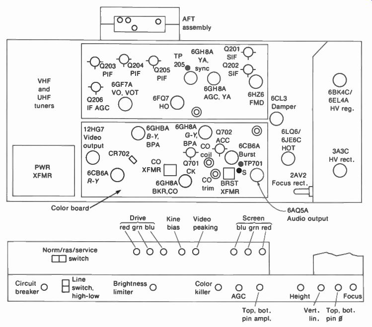
Figure 9-1 shows a common chassis layout with the setup adjustments at the back.
Most of the receiver is used for a monochrome picture on a white raster. This part includes the circuits for picture and sound signals, the raster, and the power supplies.
The 3.58-MHz color circuits are on a separate board at the rear of the chassis. Block diagrams for all these circuits are shown in two separate parts in Figs. 9-2 and 9-3. In Fig. 9-2 the monochrome part illustrates how a black-and-white picture is reproduced on the raster. Figure 9-3 shows details of the 3.58-MHz color circuits. Actually, a white raster is necessary, as a mixture of the red, green, and blue phosphors on the screen of the color picture tube. Furthermore, the Y luminance signal produces a monochrome picture. Then the color circuits can add color to the picture by providing red, green, and blue video signals for the picture tube. More details are explained in the following topics:
9-1 Requirements for the color picture tube
9-2 Normal-service switch
9-3 Monochrome circuits in a color receiver
9-4 Circuits for color
9-5 Manual color controls
9-6 Functions of the automatic color circuits
9-7 R - Y, B - Y receivers
9-8 X and Z demodulators
9-9 R, G, B receivers
9-10 How the picture tube mixes colors
9-11 Localizing color troubles
FIGURE 9-1
REAR VIEW OF CHASSIS LAYOUT WITH SETUP CONTROLS FOR COLOR TELEVISION RECEIVER (RCA CTC39 CHASSIS) -------- Circuit breaker in B+ line Heater fuse No.22 wire under chassis 7-A fuse in ac line under chassis -----------BKR = Blanker BPA = Bandpass (color) amplifier CK = Color killer CO = Color oscillator PIF = Picture IF PIN = Pincushion SIF = Sound IF TP = Test point VA = Video amplifier
9-1 Requirements for the Color Picture Tube
The details of picture tubes are described in Chaps. 10 and 11, but the requirements for the color tube in the block diagram of Fig. 9-2 can be stated briefly. The tube has three electron guns, one each for red, green, and blue. Also, the screen has either dots or vertical stripes of red, green, and blue phosphors that are excited by the three guns. All colors, including white, are produced as a mixture of red, green, and blue. The type number 21VAZP22 indicates this tube has a P22 phosphor for red, green, and blue, while the screen size is 21 in. diagonally.
The components mounted on the neck of the picture tube include the deflection yoke, convergence yoke, and purity ring magnet.
Convergence means making each of the three beams go through an aperture mask at the proper angle to excite its respective color phosphor on the screen. In brief, the functions are as follows:
1. Deflection yoke. Deflects all three beams horizontally and vertically to produce the scanning raster.
2. Convergence yoke. Has individual adjustments for each beam. Converges the beams to produce white as a combination of red, green, and blue, without color fringing at the edges of picture information.
3. Purity magnet. Positions all three beams to produce pure red, green, or blue, without any effect from the other colors. The mounting for the purity ring usually includes another small magnet called the blue lateral adjustment, for converging the blue beam horizontally.
Screen controls. These adjustments on the back of the receiver chassis vary the screen-grid voltage for each of the electron guns. The purpose is to make them all have the same cutoff characteristic. The screen controls are adjusted to produce a white raster, at a very low light level.
Drive controls. These adjustments on the back of the receiver chassis vary the amount of Y video signal for each of the electron guns The purpose is to balance the ac driving signals to compensate for different phosphor efficiencies, as the red gun may require more signal. The drive controls are adjusted to produce white highlights in a monochrome picture.
9-2 Normal-Service Switch
Most color receivers have this switch at the back of the receiver chassis to provide a raster alone, or just a horizontal line. The purpose is to help in making adjustments for the color picture tube. There are usually three settings:
1. Raster position. The AGC circuit cuts off the IF amplifier to provide a clean raster without any snow. This position may also be labeled "purity" because the raster is used when making purity adjustments for the picture tube.
2. Service or line. In this position of the switch, the vertical deflection is disabled to collapse the raster into one horizontal line across the screen. The purpose is to concentrate the illumination to help determine visual cutoff when adjusting the screen-grid voltages of the picture tube. The line may be mis-converged, with separate colors, because the convergence correction signals are missing, but this does not matter for the screen adjustments.
3. Normal. This is the operating position of the switch, with a normal picture on the raster.
Notice that setting up the color picture tube is mainly a problem of obtaining good white. More details of these setup adjustments are explained in Section 11.
9-3 Monochrome Circuits in a Color Receiver
See Fig. 9-2. The only difference in the rf and IF circuits is the importance of bandwidth for color receivers. Remember that video frequencies around 3.58 MHz just show fine detail in mono chrome, but these frequencies are essential for color information. Without the 3.58-MHz C signal, there is no color-just a monochrome picture. For this reason, the fine tuning control on the rf tuner must be tuned exactly for color in the picture, without the 920-kHz beat interference from the sound signal. Most color receivers have automatic fine tuning (AFT) which controls the frequency of the local oscillator on the rf tuner.
Intercarrier sound is used, but the sound takeoff circuit is before the video detector. The sound converter at the top of Fig. 9-2 is a diode rectifier. Input consists of P at 45.75 MHz and S at 41.25 MHz to produce the difference frequency of 4.5 MHz in the rectified output for the sound IF amplifier. A separate converter is used, instead of taking the 4.5-MHz sound from the video detector. The reason is to minimize the 920-kHz beat interference between the 4.5-MHz sound signal and the 3.58-MHz color signal.
The video detector output for a color broadcast includes the 3.58-MHz C signal multiplexed with the Y luminance signal. The waveform shown out of the video detector includes the following three components:
1. C signal for color information. This is shown for one vertical color bar down the center of the picture.
2. Luminance level corresponding to gray, midway between white and black.
3. Color sync burst of 3.58 MHz on the back porch of each horizontal blanking pulse.
The luminance information is indicated by its level between white and black. For the 3.58-MHz C signal, its average value is the luminance level.
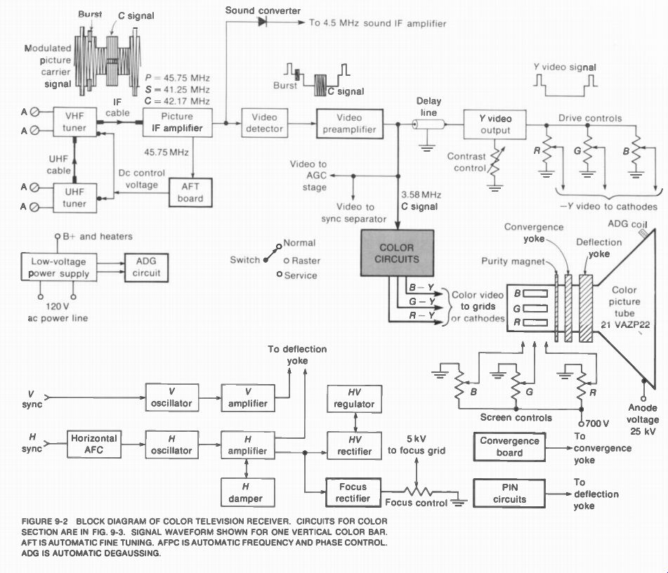
Fig. 9-2
The video amplifier in a color receiver serves as the Y amplifier, cutting off at 3.2 MHz to amplify the luminance signal without the chrominance signal. Then the video output, consisting of Y signal, is applied to each cathode of the three electron guns in the picture tube.
The red, green, and blue drive controls proportion the amount of Y signal. The combined result is a good monochrome picture, without color in the white highlights.
The video amplifier in a color receiver usually includes a preamplifier, which is usually an emitter-follower in transistor circuits. The output of the video preamplifier supplies composite video signal to several stages for different functions, as follows:
1. AGC stage for AGC bias
2. Sync separator for vertical and horizontal synchronization
3. C signal for the color section
4. Y signal for video output to the picture tube
The Y signal for the video amplifier requires a delay line. This unit delays the Y signal with respect to the C signal. Both the Y and C signals are applied to the grid-cathode circuit of the picture tube but the Y signal would be there earlier in time. The reason is that the Y video amplifier is more resistive, with more bandwidth. The time delay inserted is 0.8 u.S.
Without this delay for the Y signal, the color in formation would be out of register, about 0.3 in. to the right on a screen 20 in. wide.
The raster circuits for a color receiver are essentially the same as for monochrome, but more power is needed with a bigger yoke for the color picture tube. Flyback high voltage is used for an anode voltage of 25 to 30 kV for a 19- to 25-in, picture tube. A separate rectifier for focus voltage on the color picture tube is shown in Fig. 9-2, but this can also be obtained with a voltage divider on the high-voltage supply. In addition, the high-voltage power _supply _ usually has p regulator to maintain constant_ anode voltage with different load currents. The voltage regulation is important in maintaining focus and good converg riatn jev . In the low-voltage power supply, the ac voltage for the power line is also used for the automatic degaussing (ADG) circuit. "Degaussing" means demagnetizing. The ADG coil is around the rim at the front of the color picture tube. This coil has 60-Hz alternating current to demagnetize the tube each time the receiver is turned on or off. The degaussing is necessary to improve purity of the colors.
The convergence board shown in Fig. 9-2 supplies correction current for the convergence yoke on the color picture tube. The section labeled "PIN" includes pincushion correction circuits. These are adjusted for a rectangular raster that is not bowed in at the outside edges. Convergence and pincushion adjustments are explained in more detail in Section 11.
9-4 Circuits for Color
More details of the color section of the receiver are shown by the block diagram in Fig. 9-3.
Color receivers are generally classified according to how the luminance and color signals are combined to provide red, green, and blue for the picture tube. This addition of the Y and C signals is matrixing in the receiver. The matrixing can be done by the picture tube itself or in the circuits before the picture tube.
For matrixing in the picture tube, the R - Y, B - Y, and G - Y signals are fed to each of the guns, with the Y signal to all three. This method is generally used with vacuum tubes in the color circuits. It is classified as an R - Y, B - Y receiver, which assumes there is G - Y signal also. Figure 9-3 illustrates this type.
With transistors in the color circuits, the R - Y, B - V. and G - Y color signals are usually mixed with the Y signal before the picture tube.
Then each of the three guns has one video signal that combines red, green, or blue with the luminance information. This type is classified as an R, G, B receiver.
Input signal to the color section. We can start with the C signal from the video preamplifier in Fig. 9-3. This signal is taken off before the delay line for the Y video amplifier. The wave shape shown here includes the 3.58-MHz C signal and the color sync burst. We cannot see the hue of the C signal because the phase angle with respect to burst phase is not evident. If the C phase is the same as burst phase, the hue of the color in the C signal will be yellow-green. The amplitude of the C signal indicates the color saturation. It should be noted that the burst occurs during blanking time when there is no picture.
However, the C signal has the color information during active trace time for the picture. A1 though the burst and C signal are both 3.58 MHz, they are not present at the same time.
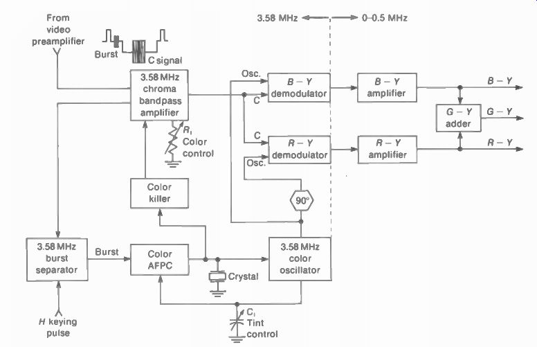
FIGURE 9-3 COLOR CIRCUITS FOR R - V. B - Y RECEIVER
Chrominance bandpass amplifier. This section includes one or two stages, fixed-tuned to 3.58 MHz as an IF amplifier, with a bandpass of - ±0.5 MHz for the modulated C signal. Although the input includes luminance and chrominance, the output is 3.58-MHz C signal because this stage is tuned to 3.58 MHz. The output includes the 3.58-MHz C signal and the 3.58-MHz burst for color sync. The 3.58-MHz output of the color amplifier is then coupled to the color demodulators to detect the color information and to the burst separator to remove the color sync burst.
The 3.58-MHz bandpass amplifier is the color or chroma amplifier, as its gain determines the amount of color in the picture.
The C signal has the frequency band of 3.58 MHz 0.5 MHz, which equals 3.08 to 4.08 MHz. A basic problem here is that the Y luminance signal also has frequency components in this band. The result can be interference between the color signal and high-frequency components of the Y signal.
This effect causes sparkle or glitter at the edges of picture information with high-frequency components.
Color demodulators. The demodulators in Fig. 9-3 detect R - Y and B - Y color video signals because these two phases are provided by the output of the 3.58-MHz color oscillator. With C signal input and B - Y phase of oscillator voltage into the B - Y demodulator, the detected output is B - Y video signal. Similarly, with C signal input to the second demodulator and R - Y phase of oscillator voltage shifted 90° from B - Y phase, the detected output is R - Y video signal.
The B - Y and R - Y video signals are combined in the proper proportions in the G - Y adder stage to produce the G - Y video signal.
Then the three color-difference voltages, B - R - Y, and G - Y, are available for the picture tube. These three color signals go to each control grid or cathode of the three-gun picture tube. The Y signal also is applied to all three cathodes. This method is equivalent to using the picture tube as a matrix to produce red, green, and blue information in the reproduced picture.
Which color video signals are detected depends on the phase of 3.58-MHz reinserted oscillator voltage. For this reason, the stages are called synchronous demodulators. Maximum output is produced for the phase of the oscillator input and 180 degrees phase. The output is minimum for the quadrature phase. With two demodulators, two color-difference voltages are detected. The receiver can also use three demodulators for red, green, and blue.
Color oscillator. This stage is a crystal-controlled oscillator, tuned to 3.579545 MHz. Its function is to generate the color subcarrier suppressed in transmission. The output is a carrier wave (cw), meaning it has no modulation.
Burst separator. The 3.58-MHz color sync burst is on the back porch of every horizontal blanking pulse. To obtain the color sync alone, the C signal is coupled into the burst separator.
This stage is a 3.58-MHz amplifier, tuned to the color subcarrier frequency, but keyed on for horizontal flyback time only. During trace time, the burst separator is held cut off. Therefore, the output is produced for 3.58-MHz signal only for the color sync burst during flyback time.
This stage amplifies the color burst alone, without the chrominance information.
Although the burst separator is a tuned amplifier for 3.58 MHz like the chrominance amplifier, they have opposite times for conduction.
The burst separator is on during flyback time and off during trace time. The chrominance amplifier is on during trace time to supply the chrominance signal needed for the color de modulators.
Color synchronization. The amplified output of the burst separator supplies the required color synchronizing voltage for the 3.58-MHz color subcarrier oscillator. Although the oscillator has a 3.579545-MHz crystal for frequency stability, its phase must be accurately controlled for correct hues in the picture. Therefore, the color sync voltage goes to an AFPC circuit. This abbreviation is for automatic frequency and phase control. Its function is to control the oscillator phase. The color AFPC circuit holds the hue of the reproduced colors at the correct values, after the manual hue or tint control has been set.
Color killer stage. This name describes its function, which is to cut off the color amplifier for programs broadcast in monochrome. The purpose is to prevent Y signal components in the 3.08- to 4.08-MHz range from being amplified in the color circuits. The result would be color noise, called confetti, in the picture, which looks like snow but with larger spots in color.
The receiver automatically recognizes a color or monochrome signal by the presence or absence of the 3.58-MHz color sync burst. This voltage is rectified to provide a dc bias that cuts off the color killer. When the killer is off, the bandpass amplifier is on for a color program.
Most receivers have a color killer adjustment on the back of the chassis. Set the control at the point where it just barely cuts off the color for a monochrome program. In some circuits, the best point is where the color just comes in.
For both cases, check that color is normal on a color program.
Because of the color killer, it is important to note that the trouble of no color sync burst causes no color, instead of no color synchronization. The reason is that no burst corresponds to a monochrome signal. This makes the color killer cut off the color amplifier.
Tuning in the color. For a program that is being broadcast in color, the fine tuning control must be set to provide chrominance signal for the receiver. Without the rf side bands corresponding to the 3.58-MHz color signal, the picture is reproduced in black and white by the luminance signal. With the fine tuning control adjusted, the color is maximum just off the point where the 920-kHz beat interferes in the picture. This is the beat frequency between the 4 5-MHz sound and 3.58-MHz color signal. The result is about 60 diagonal bars with FM "wiggles" drifting through the picture. See color plate XIII. Oscilloscope waveforms for color signals. In order to provide red, green, and blue video signals for the picture tube, the main requirements of the color section are indicated by the oscilloscope waveforms in Fig. 9-4. For transistor circuits, it is preferable to check voltages at the collector output, rather than the base input. The base-emitter junction with forward bias is actually a nonlinear diode that can distort the oscilloscope waveforms.
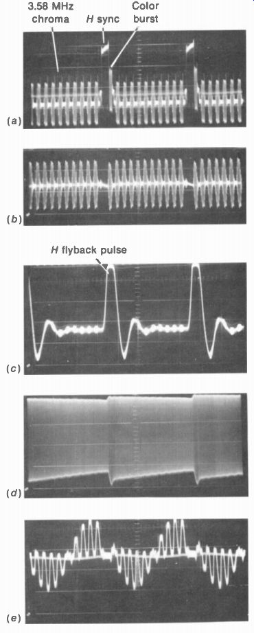
FIGURE 9-4 OSCILLOSCOPE WAVEFORMS IN COLOR CIRCUITS. WITH COLOR-BAR GENERATOR.
(a) VIDEO DETEC TOR OUTPUT. (b) 3.58-MHz C SIGNAL OF BANDPASS AMPLIFIER. (c)
INPUT TO BURST AMPLIFIER. (d) 3.58-MHz OSCILLATOR OW OUTPUT. (e) R - Y VIDEO
SIGNAL FROM DEMODULATOR.
It should be noted that the oscilloscope need not have response to 3.58 MHz in order to see the color video signals at 0 to 0.5 MHz. Furthermore, high-frequency response in the oscilloscope is used only to see individual cycles of the 3.58-MHz signal. Usually, it is just a question of seeing the amplitude of the signal. The main requirements are as follows:
1. There must be 3.58-MHz C signal into and out of the chrominance bandpass amplifier.
See Fig. 9-4a and b. Without the C signal there is no color.
2. There must be color burst to synchronize the color oscillator. The burst separator must have the horizontal keying pulse shown in Fig. 9-4c to produce the separated burst.
3. There must be 3.58-MHz cw output from the oscillator, in order for the demodulator to detect the color information in the C signal.
See Fig. 9-4d. Without the oscillator output there is no color.
4. Finally, each color video amplifier must supply detected signal to drive the three guns of the picture tube. See Fig. 9-4e. Here there can be a problem of individual colors missing, if one amplifier or one gun is not operating.
The waveforms in Fig. 9-4 are taken with a signal from a color-bar generator. A typical dot bar generator is shown in Fig. 11-3, while color plate XII shows the rainbow of color bars for every 30° of hue phase.
9-5 Manual Color Controls
The only two additional operating controls for color receivers are the color level control and tint control. These are on the front panel of the receiver.
The color control varies the amplitude of 3.58-MHz chrominance signal voltage, usually adjusting the gain of the chrominance bandpass amplifier. As a result, the intensity or amount of color in the picture is varied. The color control is also called saturation or chroma. This is R, in Fig. 9-3.
The tint or hue control varies the phase of the 3.58-MHz oscillator cw output with respect to the color sync burst. The control can be in either the oscillator or its AFPC circuit. This is C, in Fig. 9-3.
9-6 Functions of the Automatic Color Circuits
The color receiver usually has these circuits to produce the best picture without manual adjustments.
Automatic color control (ACC). This circuit controls the gain of the chrominance bandpass amplifier for a constant color level in the picture.
The idea is the same as automatic gain control (AGC) for the 3.58-MHz color IF amplifier, to prevent overload distortion. The strength of the color signal is indicated by the amplitude of burst, which is rectified to provide the dc bias for the ACC circuit.
Automatic fine tuning (AFT). This circuit controls the frequency of the local oscillator in the rf tuner to keep it tuned for the best color. There is an on-off switch to disable the AFT for cases where manual fine tuning is needed to reduce interference.
Automatic tint control (ATC). This circuit shifts the hue axis for more red to emphasize flesh tones. There is usually an on-off switch to disable the ATC if necessary.
One-button tuning. This switch turns on the AFT and ATC, and it sets the color to a preset level.
AFPC. This circuit controls the frequency and phase of the 3.58-MHz color oscillator, bycom paring its output to burst phase. The AFPC is for color lock, to hold the hues at their correct values.
Automatic degaussing (ADG). This circuit de magnetizes the color picture tube each time the receiver is turned on or off, for good purity.
Automatic brightness limiter (ABL). This circuit keeps the brightness from becoming too high, to prevent blooming in the picture.
9-7 R - Y, B - Y Receivers
In this system, the luminance and video signals are matrixed in the picture tube (Fig. 9-5). It serves as the matrix by combining the beam currents from the red, green, and blue guns. Assume that R - Y, B - Y, and G - Y color video signals are coupled to each of the control grids.
Also, -Y video signal is coupled to the three cathodes. This signal has positive sync polarity for the composite video and negative-going white amplitudes for cathode drive on the picture tube. Remember, though, that an increase in negative voltage at the cathode increases the beam current, equivalent to a positive change in grid voltage.
With -Y signal at the cathodes and color signals at each grid, they are combined as follows: B -Y - (-Y) = B -Y + Y = blue R -V- (-Y) = R -Y+ V= red G -Y - (-Y) = G -Y+ Y=green
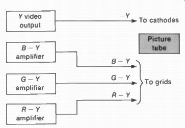
FIGURE 9-5 MATRIXING IN PICTURE TUBE WITH R V. B Y DEMODULATORS.
The -Y signal is subtracted because the effect on beam current is opposite
for cathode voltage, compared with control-grid voltage.
The matrixing to provide red, green, and blue applies only to the 0- to 0.5-MHz band for color. Actually, for fine detail in a black-and white picture, the Y signal can have frequencies up to 4 MHz. The red, green, and blue information provides a color overlay for larger areas in the picture, with video frequencies up to 0.5 MHz for the color baseband.
9-8 X and Z
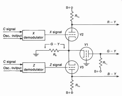
FIGURE 9-6 X AND Z DEMODULATORS USED IN R - Y,B Y RECEIVER.
Demodulators
Figure 9-6 illustrates this variation in R - Y, B - Y receivers, using the X and Z hue axes for detecting the color signal. For the X demodulator, the phase of its oscillator cw input is 282°, clockwise from burst, only 12' past - (R - Y) at 270°. For the Z demodulator the phase angle of its hue axis is 333°, which is close to - (B - Y) at 360°. The X and Z axes, then, are 51° apart. A1 though not in quadrature, the X and Z demodulators provide the advantage of balanced amplifiers for the detected color video signals. Then any drift with aging components is the same for all the colors.
The balance in Fig. 9-6 results from using identical values of load resistors Rt. Further more, the cathode resistance Rk is common for all three amplifiers. This means the signal voltage across Rk for V1 is combined with the grid signal for V2 and V3.
We can start with the output for G – Y color video signal from V1. By the choice of component values, G - Y is the color video signal developed across Rk. This is the signal input to the grounded grid amplifier V1. There is no other input signal because the grid is grounded. Since the input signal is at the cathode, there is no phase inversion, resulting in amplified output of G – Y signal from the plate of V1.
The demodulated input signal for V2 is X signal, from grid to ground. However, it has a large component of - (R - Y) because this hue axis and the X axis are so close in phase. There is also some G - Y signal in the grid voltage.
However, Rk in the cathode circuit has G - Y signal. This cancels the G - Y signal at the grid.
The combined result of the two signals between grid and cathode is - (R - Y) signal. This is amplified and inverted to produce R - Y output from V2.
The demodulated input signal for V3 is Z signal from grid to ground. This has a large component of - (B - Y) signal because this hue axis and the Z axis are close in phase. There is also some G - Y signal at the grid. With G - Y signal across Rk, the combined result of the two signals between grid and cathode is -(B - Y) signal. This is amplified and inverted to produce B - Y output from V3.
In summary, the functions of the three amplifier stages are as follows:
1. The G - Y amplifier V1 has G - Y input at the cathode and G - Y output from the plate.
2. The R - Y amplifier V2 has G - Y input at the cathode and X input at the grid. The phase of the X demodulator is 282° to make the X signal have the required components of - (R - Y) signal to be amplified in V2 and G - Y to be canceled by the signal voltage across Rk.
3. The B- Y amplifier V3 has G - Y input at the cathode and Z input at the grid. The phase of the Z demodulator is 333° to make the Z signal have the required components of - (B - Y) signal to amplify in V3 and G - Y to be canceled by the signal voltage across Rk
• It should be noted, though, that the color video signals for the picture tube are still R - Y, B - Y, and G - Y. These are matrixed with the Y signal in the picture tube, to provide red, green, and blue for the picture reproduction.
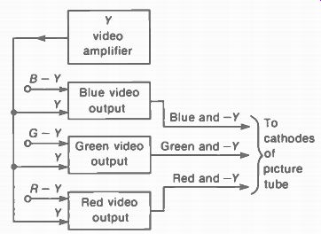
FIGURE 9-7 Y SIGNAL ADDED TO COLOR VIDEO BEFORE PICTURE TUBE IN R, G, B RECEIVER.
9-9 R, G, B Receivers
In solid-state color circuits, the matrix method in Fig. 9-7 is often used. Here, the Y signal is combined with the color video signals before the picture tube. As a result, the cathode of each gun has video signal consisting of both the luminance and the R, G, or B component.
One feature of the R, G, B method is that it can provide better tracking of color with luminance for each gun. The reason is that each video output stage supplies one video signal combining the color and luminance information. In addition, dc coupling to the picture tube provides the correct dc level for both color and luminance. However, gray-scale adjustments are easier with an R - Y, B - Y receiver, as the screen and drive controls are adjusted for a good monochrome picture. In the R, G, B receiver, the brightness and contrast controls are in the video preamplifier, before the matrixing of the Y and color signals.
An important factor is arcing or flashover to the control grid in the picture tube. With transistors, a voltage surge caused by the arc can damage the amplifier feeding signal to the control grid. In the R, G, B method, usually no video signal is applied to the control grids.
The R, G, B receiver requires three video output stages. Each has the 4-MHz bandwidth of the Y signal, instead of the 0.5-MHz band width of each color video signal. Bandwidth is not a big problem with transistor circuits, however, because of their low impedance.
The general idea of combining the Y and color video signals is illustrated in Fig. 9-8.
Across R, in the input, the signal is Y video alone. In addition, the coupling transformer T, is used to couple B - Y video for this example.
The same method can be used with R - Y or G - Y video. With the two input signals, the output across R2 includes B - Y plus Y video. They combine to equal blue video alone for color.
It should be noted that the cancellation of the Y component applies only to the 0- to 0.5-MHz band of frequencies in the color video.
For high video frequencies from 0.5 up to 4 MHz, the Y signal is not canceled. The Y signal alone has the details of picture information in mono chrome.
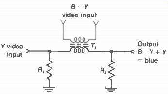
FIGURE 9-8 GENERAL METHOD OF COMBINING Y VIDEO WITH COLOR-DIFFERENCE SIGNAL
TO PRODUCE R. G, OR B VIDEO.
9-10 How the Picture Tube Mixes Colors
You do not see the individual dots or stripes of phosphor colors on the screen. Therefore, the eye integrates the effects of red, green, and blue light emitted by the phosphors. The intensity of each color increases with more beam current.
Furthermore, the amount of beam current is controlled by the cathode-to-grid signal voltage.
To make a white raster on the screen, the beam currents for the red, green, and blue guns are proportioned to produce white. The dc voltages for the electron guns are set by the screen adjustments for a white raster at a low light level.
For a lighter white in the picture information, the red, green, and blue beam currents are increased in proportion by video signal for the three guns. Black in the picture is just the absence of light, as a result of cutting off beam current.
Suppose the picture information is blue.
Then the blue gun operates, without any beam current from the red and green guns. Similarly, red or green can be produced by beam current from each gun, without any contribution from the other colors.
Suppose the picture information is yellow.
Then the red and green guns operate without blue. For orange, more red can be added.
Similarly, the green and blue guns produce beam current for the combination of cyan. Also, red and blue are added for magenta or violet.
This addition of colors by the picture tube illustrates why the inverted polarity of a color video voltage is its complementary color. Consider white information, combining red, green, and blue. Suppose that the blue component of video voltages is inverted in polarity. In terms of the picture tube, we can consider that positive blue video grid voltage increases the beam current for the blue gun. When the polarity is inverted to negative blue video voltage, now this video signal decreases the beam current. however, the red and green components stay the same. The yellow combining red and green is stronger, therefore, with less blue. If the blue is removed completely, the result will be yellow alone. The result, then, is that negative blue corresponds to yellow. Similarly, negative red corresponds to cyan with blue and green. Also negative green corresponds to magenta with red and blue. In each case, the negative polarity refers to inverting the effect on the amount of beam current in the picture tube.
9-11 Localizing Color Troubles
It can be useful to consider that the color is superimposed on a monochrome picture on a white raster. White in the raster is set by the combination of R, G, and B screen-grid controls for the picture tube. The monochrome picture is produced by the combination of R, G, and B drive controls for Y video signal to the three guns. Color is added by the 3.58-MHz chrominance signal, demodulated into separate color video signals. The 3.58-MHz C signal is for all the colors, but the demodulated video signals are for individual red, green, or blue.
Another important factor in separate colors is the picture tube with its three electron guns. When one gun does not operate, that color is missing. Typical troubles in one gun are weak emission or a cathode-heater short. The short circuit to the grounded heater kills video signal coupled to the cathode.
Raster not white. This can be caused by the wrong dc bias voltages at the cathode of each gun, or by incorrect settings of the R, G, and B screen controls on the color picture tubes. Then the raster has too much of one color, or not enough, resulting in a raster that has color in stead of being white.
The trouble of an individual color in the entire raster can result from a defective picture tube. Weak emission from the cathode and a short circuit at the cathode or control grid are typical troubles for one gun alone.
It should also be noted that the color video amplifiers are often dc-coupled to the picture tube. Then a trouble that changes the dc voltages in the amplifier stage will affect the bias voltage for each gun. The dc coupling is illustrated in Fig. 9-9. Here the bias is 200 - 140 = 60 V, negative at the control grid of the picture tube.
Monochrome picture not white. Color in the raster will also cause color in a monochrome picture. However, the raster can be white while the monochrome picture has color when the Y video signals are not balanced for the three guns. Check the R, G, and B drives for Y signal to each gun. Also, a cathode-to-heater short in one gun means this component of the Y signal will be missing.
No color. Assuming a normal raster and a good monochrome picture, no color at all means there is no 3.58-MHz chrominance signal or no 3.58-MHz oscillator cw output. These stages are necessary to all the color video signals. Re member that the color killer cuts off the bandpass amplifier if there is no burst signal.
Weak color. This means weak 3.58-MHz color signal. Check the chroma bandpass amplifier. However, it must have normal color signal from the rf, IF, and video circuits.
One color missing. Check if the monochrome picture is white. If not, one gun may be shorted for Y signal. If white is normal, then one of the R - Y, B - Y, or G - Y color video signals may be missing. Where the picture tube is used as the matrix, one gun can be shorted for Y video at the cathode but not for color video at the grid.
Wrong hues. Check that the raster and mono chrome picture are white. If they are, then check color oscillator phase. Correct alignment of the AFPC circuit and chroma bandpass amplifier is necessary for correct hues.
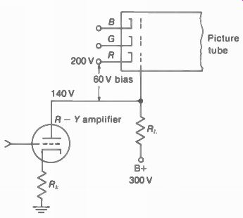
FIGURE 9-9 DC COUPLING TO PICTURE TUBE DETER MINES ITS BIAS
Color bars in picture. See color plate VI. These bars indicate no color sync. Check the AFPC circuit.
Changing hues in picture. This effect indicates weak color sync. Check the AFPC circuit.
------------------
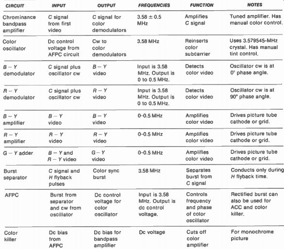
TABLE 9-1 FUNCTIONS OF THE COLOR STAGES (for block diagram in Fig. 9-2)
CIRCUIT INPUT OUTPUT FREQUENCIES FUNCTION NOTES
Chrominance bandpass amplifier C signal from first video C signal for 3.58 ± 0.5 color MHz demodulators Amplifies C signal Tuned amplifier. Has manual color control.
Color oscillator
Dc control voltage from AFPC circuit
Cw to color demodulators 3.58 MHz
Reinserts color subcarrier
Uses 3.579545-MHz crystal. Has manual tint control.
- Y demodulator C signal plus B - Y oscillator cw video Input is 3.58 Detects Oscillator cw is at MHz. Output is color video
0' phase angle.
0 to 0.5 MHz.
R- Y demodulator C signal plus R - Y oscillator cw video Input is 3.58 Detects Oscillator cw is at MHz. Output is color video 90° phase angle.
0 to 0.5 MHz.
B - Y - Y amplifier video B - Y video
0-0.5 MHz Amplifies color video
Drives picture tube cathode or grid.
R- Y amplifier R- Y video R- Y video
0-0.5 MHz
Amplifies color video
Drives picture tube cathode or grid.
G- Y adder B- Y and G- Y R - Y video, video
0-0.5 MHz Amplifies color video
Drives picture tube cathode or grid.
Burst separator C signal and Color sync H flyback burst pulses 3.58 MHz Separates burst from C signal Conducts only during H flyback time.
AFPC Burst from separator and cw from oscillator Dc control voltage for color oscillator Input is 3.58 MHz. Output is dc control voltage.
Controls frequency and phase of color oscillator Rectified burst can also be used for ACC and color killer.
Color killer
Dc bias from AFPC Dc bias for bandpass amplifier Dc voltage Cuts off color amplifier For monochrome picture
------------------
SUMMARY
The stages in the color section of the receiver are summarized in Table 9-1, with their input and output signals, frequencies, and functions. Notice there is only one chroma signal at 3.58 MHz before the demodulators, but after detection the color in formation is in separate color video signals with a bandwidth of 0.5 MHz.
Self-Examination (Answers at back of guide)
Answer True or False.
1 The color saturation control varies the amount of C signal.
2. The tint _p_control varies the phase of the color oscillator output with respect to burst. 1
3. The chrominance bandpass amplifier is tuned to 3.58 MHz. 7
4. The G - Y adder stage is tuned to 3.58 MHz. 1 -
5. The R, G, B drive controls vary the amount of Y signal.
6. The R, G, B screen controls vary the amount of C signal.
7. The color killer is cut off on a color program.
8. The R - Y demodulator is in quadrature with the B - Y demodulator.
9. B - Y phase is 180° opposite from burst phase.
10. The burst amplifier separates the color sync burst from the C signal.
11. The 3.579545-MHz crystal oscillator is needed to reinsert the color subcarrier.
12. Color bars in the picture indicate no color AFPC.
13. When R - Y, B - V. and G - Y color video signals are coupled with Y signal to the picture tube, it serves as the matrix.
14. The normal-service switch is used for purity and screen adjustments on the picture tube.
15. Color receivers generally use the video detector to produce, the 4.5-MHz inter carrier sound signal.
16. A 920-kHz beat pattern in the picture is interference between the color and sound signals.
17. When blue video signal is inverted in polarity, the hue becomes yellow.
18. If one gun does not operate, the monochrome picture will not be white.
19. If the color oscillator does not operate, there will be no color in the picture.
20. A white raster depends on the gain of the R - Y, B - Y, and G - Y amplifiers.
Essay Questions
1. Give five differences between color and monochrome receivers, not counting the circuits in the color section.
2. Give the frequencies and functions for the following stages: (a) chrominance bandpass amplifier; (b) color oscillator; (c) B - Y demodulator; (d) B - Y amplifier; (e) burst separator.
3. Describe briefly how the color control and tint control function.
4. Describe briefly how to set the fine tuning control manually for color in the picture.
5. What controls are adjusted for a white raster?
6. What controls are adjusted for a white picture?
7. Give the two input voltages and one output for the burst separator.
8. Give the two input voltages and one output for the R - Y demodulator.
9. For the following abbreviations of automatic circuits, give the meaning and the circuit each controls: AFT, ACC, ATC, AFPC, ADG, and ABL.
10. Give the functions for the three positions of the normal-service switch.
11. Compare the methods of matrixing for an R - Y, B - Y receiver and R, G, B receiver.
12. How do X and Z demodulators differ from R - Y and B - Y demodulators?
13. Give the function of the color killer stage.
14. Give two color troubles in the picture with a possible cause for each.
15. Why is the color level control in the chroma amplifier, rather than the B - V. R - Y, or G - Y amplifier?
16. Explain briefly why the brightness control in the Y video amplifier can vary the bias for all three electron guns in the picture tube.
17. Why is the burst separator on during horizontal retrace time? 18. Why is the chroma amplifier on during horizontal trace time?
Problems
1. For channel 3, 60 to 66 MHz, give the following frequencies in the receiver: (a) rf local oscillator in the VHF tuner; (b) picture, color, and sound carriers in the rf amplifier; (c) picture, color, and sound carriers in the picture IF amplifier; (d) color signal out of the video detector.
2. Referring to Fig. 9-9, if the R - Y amplifier does not conduct any plate current, calculate the (a) plate voltage; (b) grid bias for picture tube.