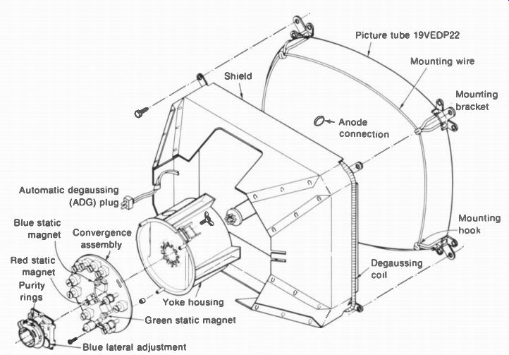
Figure 11-1 shows a typical mounting assembly for a color picture tube in the receiver cabinet. This is a delta-gun tube, using a shadow mask with a phosphor-dot screen.
The magnetic components on the neck include the deflection yoke against the wide bell, the convergence magnet assembly for red, green, or blue, and the purity magnet assembly, which also has the blue lateral magnet near the tube base. The convergence assembly, over the internal convergence cup, usually is about 0.5 in. from the deflection yoke, and the purity rings are 1 in. behind, at the space between grids 1 and 2. These magnets are all adjusted for correct purity and convergence on the phosphor-dot screen. Also shown is the external magnetic shield, with a wraparound degaussing coil for demagnetizing the picture tube. More details of the setup adjustments for this type of color picture tube are explained in the following topics:
11-1 Color purity
11-2 Color convergence
11-3 Convergence correction waveshapes
11-4 Screen-grid adjustments
11-5 Degaussing
11-6 Pincushion correction
11-7 Overall setup adjustments
FIGURE 11-1 EXPLODED VIEW OF MOUNTING ASSEMBLY FOR COLOR PICTURE TUBE WITH
DELTA GUNS. SHADOW MASK, AND PHOSPHOR-DOT TRIOS. (RCA CTC71 CHASSIS)
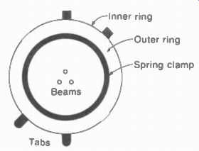
FIGURE 11-2 CONSTRUCTION OF PURITY MAGNET
11-1 Color Purity
Each beam should strike the center of each color dot. Then the light is a pure color, without any mixing from the other two. Obtaining good purity, therefore, is also called the beam-landing adjustment. The test of good purity is a white raster that does not have any areas of color. The white raster means that pure red, green, and blue are produced by the color phosphors, forming a pure white mixture.
An example of poor purity is shown in color plate III, with patches of other colors in a red raster. With only one beam operating, the raster should be a uniform red, green, or blue.
The purity is usually adjusted for a solid red raster. Red is preferred because this phosphor requires the most beam current. Then any misadjustment of beam landing has the greatest effect on purity.
The position of the purity magnet near the base of the picture tube, between grid 1 and grid 2, is illustrated in Fig. 11-1, while Fig. 11-2 shows a closer view of the ring magnets. Although the purity assembly usually has a blue lateral mag net for convergence, this is not used for the purity adjustments.
The purity assembly serves as a centering magnet for all three beams. The two rings have tabs, one square and the other rounded, to mark the opposite ends. When the same tabs are together, the ring magnets are bucking and there is no net magnetic field to shift the position of the beams. Spreading the tabs produces a stronger field for a greater effect in positioning. Rotating both rings together changes the direction of the shift in centering. You can move the beams up or down or at a diagonal.
The purpose of this positioning is to make the beams begin deflection from the correct point at the center of the area surrounded by the deflection yoke. Otherwise, the beam landing cannot be correct when the beams are deflected to form the raster. The purity magnet is adjusted for a pure red area in the center of the raster, with only the red gun operating.
No signal is used when checking purity because this test is for the raster, not for the picture. In receivers with a service switch, it is set to the raster position for purity adjustments.
Correct adjustment of purity is critical for proper colors and good convergence. Do not try to adjust a tube just brought in from the cold.
The tube should be operating at a high brightness level for at least 10 min. Difficulty in adjusting purity may mean that manual degaussing is necessary. (See Sec. 11-5.) Also, the convergence assembly must be in its correct position for static convergence at the center.
With only the red gun operating for a red raster, the following procedure can be used to adjust purity:
1. Loosen the deflection yoke and move it back toward the convergence assembly. In many cases, there are wing nuts at the sides of a plastic housing for the yoke.
2. Rotate purity ring and separate the tabs, if necessary, to produce a pure red area at the center of the screen. Start with similar tabs together and rotate both rings. If the red is centered, this is all that is needed; if not, separate the tabs and rotate the rings again.
3. After the pure red is centered, push the deflection yoke forward to produce a uniform red raster over the entire screen area.
Make sure the raster is not tilted. In most cases, the yoke will be up against the bell of the tube, but use the position that produces the best purity at the edges.
After a pure red raster has been obtained, operate the green and blue guns alone to check the green raster and blue raster. Usually, when the red raster has good purity, the green and blue rasters look even better. With the correct purity, all three guns can operate to produce a solid white raster.
11-2 Color Convergence
The process of adjusting each beam separately to make all three beams hit the same spot is convergence. Otherwise, the result is color fringes around the edges of objects in the picture. This effect of a color outline is only seen with a picture, especially in black and white. The raster can be perfect because it has no picture information with edges. An example of color fringing because of poor convergence is shown in color plate II.
Dot-bar generator. See Fig. 11-3. This type of signal generator is usually needed for convergence adjustments. It produces rows of dots or a crosshatch pattern of lines, all in black and white for observing the convergence, plus color bars for testing the color circuits. The dot pat tern is shown in Fig. 11-4a with the crosshatch in b. These patterns are used for the picture because you need vertical and horizontal edges that stay still in order to see color fringing.
When the dots and lines are white without any colors at the edges, this result shows convergence of red, green, and blue.
The dot-bar generator in Fig. 11-3 also has a super-pulse setting to produce one white rectangle in the center of the picture. The output is available on either channel 3 or channel 9 for the receiver antenna terminals, at IF signal frequencies, or as video signal into the video amplifier. The dot pattern is generally used for adjustments at the center, which is static convergence. The adjustments for dynamic convergence at the borders of the screen usually require the crosshatch pattern.
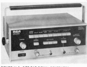
FIGURE 11-3 DOT-BAR SIGNAL GENERATOR. WIDTH IS 10 IN. (RCA)
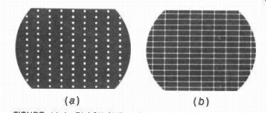
FIGURE 11-4 BLACK-AND-WHITE PATTERNS USED FOR CONVERGENCE ADJUSTMENTS. (a)
DOTS. (b) CROSS HATCH.
Convergence yoke. See Fig. 11-5. The entire assembly is mounted over the internal pole pieces of the three guns. Then the magnetic flux provided by each section is confined to affect only the one beam. Adjusting the strength of the flux from the convergence magnets moves each beam slightly. Because of the delta arrangement with the guns 120c apart, the red and green beams move diagonally, when you watch the dot pattern on the screen. However, the blue beam moves vertically. For this reason, the blue gun also has the lateral adjustment magnet to move the blue beam left or right. The blue lateral mag net is usually part of the purity ring assembly (Fig. 11-1). It should be noted that the picture tube can be designed to move any one beam vertically and horizontally, while the other two move diagonally for convergence, but blue is generally used for the perpendicular displacements.
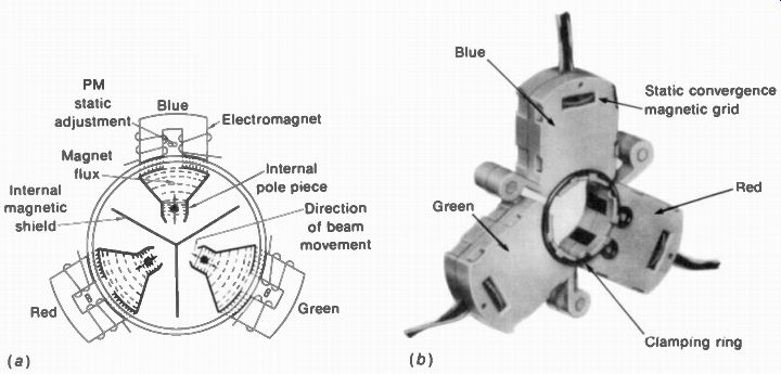
FIGURE 11-5 RADIAL CONVERGENCE MAGNET ASSEMBLY. (a) CONSTRUCTION.
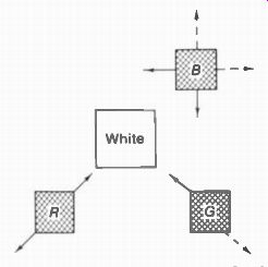
FIGURE 11-6 EFFECT OF STATIC CONVERGENCE MAGNETS IN MOVING COLOR DOTS TO
PRODUCE WHITE.
The net result of the four possible displacements allows convergence of the three beams to produce white, as shown in Fig. 11-6.
Only one dot at the center is shown. Assume that there is no convergence to start. Adjust the red magnet to move the red dot diagonally about '/, in. up to the right. Then use the green magnet to move the green dot up a little to the left to form a yellow dot. Next you can move the blue dot down with the blue magnet to be next to the yellow dot. Finally, the blue lateral magnet will move the blue beam to the left to converge all three beams for a white dot.
Each convergence magnet consists of a permanent magnet and an electromagnet. The permanent magnets are usually adjusted by turning small plastic thumbwheels. Blue is generally at the top and center of the delta. The magnets can move each color dot about ±1/2 in., but the required adjustment is usually much less. Adjusting the permanent magnets is static convergence. In addition, there is a coil magnet for each gun. The coil magnets have correction current from the deflection circuits for dynamic convergence at the top, bottom, left, and right edges of the screen.
Static convergence adjustments. Make sure the raster controls for height, width, focus, and high voltage are set properly before convergence is adjusted. It is usually easy to adjust the static magnets for white dots over about 50 percent of the screen area at the center. First, move red and green in their opposite diagonals to merge into yellow. Then adjust the blue vertically and laterally to produce white dots. With a crosshatch pattern, the lines at the center will be white without color fringing. However, the edges may need converging, as shown in Fig. 11-7. The static convergence at the center must be correct before doing the dynamic convergence for the edges.
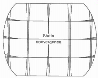
FIGURE 11-7 CROSSHATCH PATTERN WITH GOOD STATIC CONVERGENCE AT CENTER BUT
POOR DYNAMIC CONVERGENCE AT EDGES OF SCREEN.
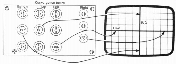
FIGURE 11-8 CONVERGENCE-BOARD ADJUSTMENTS WITH EFFECTS ON CROSSHATCH PATTERN
(RCA CTC46 CHASSIS)
Dynamic convergence adjustments. The adjustments may be on the convergence yoke, as in Fig 11-1, or on a separate convergence board, as in Fig. 11-8. The board usually mounts at the top of the cabinet so that you can vary the controls while watching the screen from the front.
There are about 12 adjustments to converge the crosshatch pattern for white lines at the top, bottom, left, and right edges. The controls include adjustable coils to vary the phase of the convergence correction current and variable resistors to adjust the amplitude.
Usually, red and green are adjusted together, separate from blue. If necessary, the blue beam can be killed temporarily to watch only red and green. Or, blue can be moved out for separate lines by adjusting the blue lateral mag net. After red and green are converged for yellow lines throughout the picture, the blue can be moved in by the static magnets for a white crosshatch pattern. When the manufacturer's service notes are available, follow this procedure to save time for dynamic convergence.
Do not be afraid to separate the colors, especially blue, if this helps in making the dynamic convergence. Normally, it is easy to merge all the colors again with the static mag nets. Watch for fringing that is the same at the edges and the center. For instance, suppose that all the bars or dots across the screen have blue fringing, always to the right. This can easily be corrected by a slight readjustment of the blue lateral magnet. In general, the static convergence should be checked periodically while adjusting the dynamic convergence. The convergence at the center should be perfect, while the edges are usually about 80 to 90 percent converged.
Once the convergence has been done, the adjustments are stable. However, do not make any big changes in focus, height, or width of the raster. Receivers delivered from the manufacturer are converged. The only time the complete adjustments may be necessary is when the picture tube is changed.
11-3 Convergence Correction Waveshapes
Basically, a parabola is needed for the wave shape of correction current in the coils of the convergence yoke. As shown at the top of Fig. 11-9, the parabola has symmetrical values at its two peaks, with little amplitude in the middle. In a parabola for vertical deflection at 60 Hz, the start and finish correspond to the top and bottom of the raster. A parabola for horizontal deflection at 15,750 Hz corresponds to the left and right sides. As a result, parabolic wave forms are used for dynamic convergence at the edges of the screen, with little effect on the static convergence at the center.
The parabolic waveform can be obtained by charging a capacitor with sawtooth current.
This method is used for both vertical and horizontal parabolas. Convergence fields in synchronism with the scanning are the result of using output from the vertical and horizontal deflection circuits.
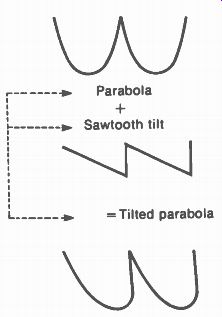
FIGURE 11- 9 WAVEFORMS FOR DYNAMIC CONVERGENCE CORRECTION SIGNALS. TWO CYCLES
SHOWN.
In addition to the parabola, a sawtooth component is added to tilt the waveform, as shown in the parabola at the bottom of Fig. 11-9.
The tilt is necessary to favor one end with respect to the other. Both the vertical and horizontal correction parabolas need the tilt because of the position of the guns in a delta.
For instance, the electron beam from the blue gun at the top must travel further when deflected to the bottom of the screen, compared with the top. Also, the red and green guns are mounted below center. Therefore, these beams travel further to the top. In addition, the red and green are off center horizontally. This requires tilt for horizontal dynamic convergence. Actually, the dynamic convergence adjustments for red and green are combined to reduce the number of controls.
The tilted parabola can correct for un equal distances to the edges of the screen, for each beam in a delta gun. Opposite polarities for the sawtooth component produce opposite directions of tilt. For vertical scanning, the correction can be increased either at the top or bottom. Similarly, the convergence correction can be increased left or right by reversing the tilt of the parabola for horizontal correction. For both cases, though, the parabolic correction does not affect the center, where the permanent magnets provide static convergence.
To help in reducing the effect of dynamic adjustments on the center convergence, the correction circuits generally use clamping diodes.
A diode clamp circuit keeps the middle of the parabola at a fixed voltage value. The purpose is to maintain the center value while adjusting the parabola tilt and amplitude. A typical convergence diode assembly is shown in Fig. 11-10.
The parabolic correction signals are connected to the coils in the convergence yoke, as shown in Fig. 11-11, not to the deflection yoke.
Note that separate coils are used for the vertical and horizontal correction signals. The electromagnet is illustrated for the blue gun, but the construction is the same for the red and green mag nets. It should be noted, though, that the red and green magnets are connected in series with each other. As a result, they both have the same vertical and horizontal deflection signals. Also, only one set of controls is used for both red and green convergence. This convenience is possible because the red and green guns require similar dynamic correction. Both guns are in the same horizontal plane, and they are displaced by the same amount off-center.
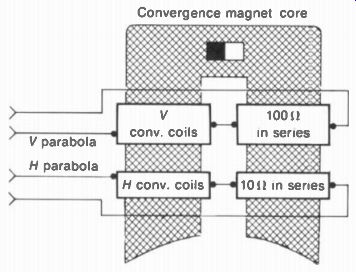
FIGURE 11-11 ILLUSTRATING HOW BOTH THE VERTICAL AND HORIZONTAL CORRECTION
SIGNALS ARE CONNECTED TO THE CONVERGENCE MAGNET. THIS CONSTRUCTION IS THE
SAME FOR THE BLUE. GREEN. AND RED MAGNETS.
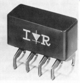
FIGURE 11-10 CONVERGENCE RECTIFIER ASSEMBLY WITH FOUR DIODES LENGTH IS 1
IN (INTERNATIONAL RECTIFIER)
11-4 Screen-Grid Adjustments
These controls on the back of the receiver chassis adjust the screen-grid dc voltage for each gun. They are usually called red screen, green screen, and blue screen. The screen adjustment for each gun determines how much voltage is needed at the control grid to produce cutoff for black and the maximum beam current for white highlights.
The screen controls are dc adjustments for the raster, without signal. To see this effect, remove the picture to view the raster alone. If you turn up the red screen, with the other two controls down, you will see a red raster.
Similarly, green or blue can be turned up, with the others down, to see just the one color. If you turn up the red screen and green screen, without blue, you will see a yellow raster. Add blue, and the raster becomes white.
The screen adjustments determine how the three beam currents will be balanced to make white. The purpose is to obtain a bright picture, while still maintaining proper white and gray, without color, for all settings of the brightness control. For this reason, the adjustment is often called black-and-white setup, gray-scale tracking, or white color temperature. The degree of white is specified in terms of tempera ture, usually at 9000 K. This white has a little more blue than the reference white of 6500 K, but people seem to prefer a bluish white on the television screen.
Actually, most adjustments for a color picture tube are made on white because this is the first requirement for having the correct colors.
In brief, the screen-grid adjustments are set to produce a white raster. In a receiver with a normal-service switch and separate screen controls, the procedure can be as follows:
1. Preliminary. Brightness, contrast, and color controls at their normal positions.
2. Set the normal-service switch for just a horizontal line on the screen.
3. Turn all the screen adjustments down to cut off the line on the screen.
4. Turn the red screen up to the point where the red line is just barely visible. Then turn up the green screen for a faint yellow line and the blue screen for a white line. In each case, adjust to the point where the line is barely visible or just cut off.
5. Set the normal-service switch to the position that produces a raster, which should now be white. If the raster is not white, the screen controls can be readjusted slightly. Vary the brightness control to see that the raster is white for different brightness settings.
6. In the "normal" position of the service switch, check for a good black-and-white picture.
If any screen control does not produce a line, readjust the brightness control to make the line visible. Also, if the raster is not bright enough after the screen adjustments have been made, try readjusting them at a lower setting of brightness.
Then the brightness control can be turned up for a lighter raster. Usually, at least one of the screen controls should be at its maximum setting.
If the raster tracks from light to dark but there is some color in white highlights of the picture, try readjusting the red, green, and blue drive controls. These adjust the amount of Y luminance signal for the three guns. In some cases, it may be necessary to rearrange the cathode leads for drive to the three guns. These wires are yellow with red, green, or blue tracers.
11-5 Degaussing
This term refers to demagnetizing iron and steel parts of the picture tube. Specifically, the steel shadow mask with its frame inside and the metal hood around the tube can become magnetized by a steady magnetic field. The main effect is from the earth's magnetic field (terrestrial magnetism). This magnetization affects the beam register on each color phosphor, causing poor purity, especially at the edges. When perfect purity is a problem, degaussing may be necessary.
In general, the principle of demagnetizing is to use the varying magnetic field of an alternating current and slowly reduce it to zero. The 60-Hz current from the ac power line is used.
Automatic degaussing (ADG). Receivers now have a coil around the front rim of the picture tube for automatic degaussing. In Fig. 11-1, the coil is wrapped around the metal hood made of 0.5-mm silicon steel. Current for the coil is taken from the 60-Hz ac power line. When the set is turned on, a high value of alternating current flows, which is then reduced to zero by the ADG circuit. In some receivers, the automatic degaussing operates when the set is turned off.
In either case, the ADG circuit automatically degausses the picture tube each time the receiver is turned on or off. Because of the automatic degaussing, the receiver does not have to be facing in any particular direction with respect to the earth's magnetic field.
ADG circuit. A typical circuit for automatic degaussing is shown in Fig. 11-12. When the receiver is turned on, the ac voltage drop across the thermistor is about 70 V. This voltage is applied to the ADG coils in series with the vans tor. As the thermistor heats up with current, its resistance decreases. At the same time, the varistor resistance increases. Then the voltage across the ADG coils decreases, resulting in less current for degaussing. As a result, the current in the degaussing coils drops from about 2 A to practically 0 in less than 1 S. The receiver must be off for about 30 min for the thermistors to cool down to room temperature, or else the ADG circuit will not demagnetize the picture tube.
Manual degaussing. In some cases, it may be necessary to demagnetize the picture tube with a separate degaussing coil (Fig. 11-13). Connect the coil to the 60-Hz ac power line. Hold it up to the screen, and move the coil around the top, bottom, and sides of the picture tube. After about 5 s, move the coil slowly at least 6 ft away, put the coil on the floor, and shut off the current.
The purpose of moving the coil away and laying it flat is to prevent its magnetic field from affecting the picture tube when the de-magnetizing field collapses. Otherwise, the transient crop of current in midcycle can magnetize the tube.
The requirements for degaussing are typically 2-A current through 45 deg. turns of No. 20 wire, with a coil diameter of 12 to 13 in. This arrangement produces the magnetomotive force of 900 ampere-turns.
11-6 Pincushion Correction
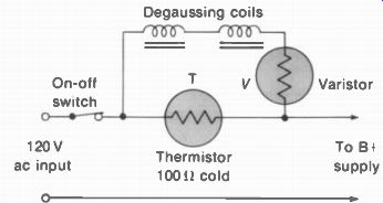
FIGURE 11-12 CIRCUIT FOR AUTOMATIC DEGAUSSING (ADG)
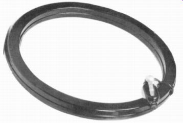
FIGURE 11-13 DEGAUSSING COIL WITH- SWITCH FOR POWER-LINE CORD. (WALSCO ELECTRONICS)
The pincushion shape of the raster is shown in Fig. 11-14. The reason for the distortion is that the corners of a flat screen are further from the point of deflection, compared with the center.
Then the electron beam is moved more horizontally and vertically at the extreme angles of deflection. The pincushion problem is more severe with wide-angle tubes of 90 deg. or more.
For monochrome picture tubes, the pin cushion distortion is corrected by permanent magnets mounted on the housing of the deflection yoke. These pincushion magnets cannot be used with color picture tubes, however, because they would affect the three beams by different amounts, resulting in more problems with color purity and convergence. Therefore, dynamic pincushion correction is used with color picture tubes.
The pincushion correction signals are applied to the deflection yoke. The horizontal scanning coils have pincushion correction current to straighten the sides of the raster. The vertical scanning coils have pincushion correction current to straighten the top and bottom of the raster.
Horizontal pincushion correction. The problem here is to push out the sides of the raster, at the center. Thus more horizontal scanning current is needed for the horizontal lines produced midway between the top and bottom. To accomplish the side correction, the horizontal deflection current at 15,750 Hz is modulated at the vertical scanning rate at 60 Hz. The vertical modulation is a 60-Hz parabolic waveform, which stretches the width of the horizontal lines in the middle of the vertical scan but not at the start and finish.
The circuit generally used for horizontal pincushion correction is illustrated in Fig. 11-15.
The vertical modulation is taken from the vertical output circuit. This sawtooth component is shaped into a parabola by C, and R, in parallel.
Then the B voltage for the horizontal amplifier is in series with the 60-Hz parabolic voltage. As a result, the amplitude of individual cycles of the 15,750-Hz horizontal output varies in step with the 60-Hz component in the supply voltage. The modulated waveform of current for the horizontal deflection coils shows that the horizontal amplitude is increased for more width for those scanning lines in the middle of the raster. This pincushion correction signal, therefore, has the effect of pulling out the center to straighten the sides.
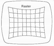
FIGURE 11-14 PINCUSHION DISTORTION OF RASTER.
FIGURE 11-15 HORIZONTAL PINCUSHION CORRECTION FOR SIDES OF RASTER.
Vertical pincushion correction. Also called top-and-bottom (TB) correction, vertical pin cushion correction requires current in the vertical scanning coils with three features: (1) more vertical deflection in the middle of the horizontal lines; (2) correction only at the top and bottom of the raster; (3) opposite corrections at the top and bottom. Then the vertical pincushion correction current will stretch the raster upward at the top and pull the raster down toward the bottom, at the center of the raster. The correction should be zero at the vertical center.
The waveshapes required for the TB correction are illustrated in Fig. 11-16a. First is the 60-Hz sawtooth scanning current, without pin cushion correction. Note that this waveform (1) is a negative-going sawtooth. More amplitude in the positive direction at the start will stretch the top of the raster. More negative amplitude at the finish will stretch the bottom. Next is shown the waveshape (2) of 15,750-Hz correction current.
This waveform (2) can include sine waves, clipped sine waves, or parabolic waves derived from the horizontal output circuit. These amplitudes decrease to zero at the center of the vertical scan and then increase with opposite polarity. The combined waveform (3) for vertical pincushion correction then has the butterfly component shown in darker shading. This correction has the following effects:
1. At the top of the raster, the vertical scanning current is increased in the direction of more height at the top just for the center of the horizontal lines. The PIN phase control adjusts the phasing of the horizontal component to put the correction in the middle of the lines.
2. At the vertical center there is no TB correction.
3. At the bottom of the raster, the vertical scanning current is increased in the direction of more height at the bottom, just for the center of the horizontal lines.
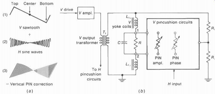
FIGURE 11-16 VERTICAL PINCUSHION CORRECTION FOR TOP AND BOTTOM OF RASTER
(a) WAVEFORMS ( I D) CONNECTIONS TO VERTICAL COILS IN DEFLECTION YOKE
The circuit arrangement for supplying the vertical pincushion correction current for the vertical scanning coils in the deflection yoke is illustrated in Fig. 11-16b. The dark outline indicates the board that has the PIN correction circuits. For vertical correction, the combined waveshape (3) in Fig. 11-16a is available at points 1 and 2 between the vertical coils L_g1 and L_g2. The RC network here provides a low impedance for connection to the PIN board. Actually, the entire vertical PIN circuit is a low impedance between the center of the yoke coils and the center tap of the damping resistors R1 and R2.
A common method of obtaining waveform (2) in Fig. 11-16a uses a saturable reactor. This reactor is a special transformer with a closed iron core that can be easily saturated. One winding serves as a control winding to saturate the core.
Pincushion adjustments. There usually are no adjustments for side pincushion correction. The vertical TB controls are factory-set and seldom need adjustment. If necessary, the adjustments are made on a crosshatch pattern. The PIN phase control is adjusted to move any curvature of the horizontal lines to the middle. Then adjust the PIN amplitude control for straight scanning lines at the top and bottom of the raster. In some receivers, there may be a permanent magnet adjustment on the saturable reactor to adjust the crossover point between top-and-bottom correction.
11-7 Overall Setup Adjustments
When a color picture tube is installed, it may be necessary to do a complete job on purity, convergence, and gray-scale tracking. First, make sure all the simpler adjustments not related to color are set properly. These adjustments include height and width of the raster, with good focus and the required amount of high voltage.
Any changes can affect the purity and convergence. Pincushion correction of the raster usually need not be readjusted, but, if necessary, this should be done now. Then start on the adjustments for the color picture tube. The following steps illustrate the usual sequence.
Step 1: Degaussing. Although the receiver has ADG, it usually helps in adjusting purity and convergence to do manual degaussing first. Have the receiver in its normal viewing position. Then the degaussing field can neutralize the effect of the earth's magnetic field.
Step 2: Purity. Adjust the purity magnet for the red "fireball" at the center of the raster, with only the red gun operating. Set the deflection yoke approximately for good red around the edges.
Step 3: Static convergence. Turn on all three guns for white. Connect the generator for a dot pattern. Adjust the permanent magnets on the convergence yoke to converge red, green, and blue for white dots at the center.
Step 4: Recheck purity. If the static convergence required much adjustment, the purity magnet should be checked again. Now you can tighten the deflection yoke in its final position for good purity at the edges. Be sure the raster is not tilted. Check the purity for red, green, and blue. Then combine the colors for a white raster.
Step 5: Dynamic convergence. Switch the generator to the crosshatch pattern. The manufacturer's instructions should be followed for dynamic convergence. However, the general procedure is to converge all the lines in the crosshatch, as follows: Vertical center line, for RIG Vertical lines at left and right, for RIG Horizontal lines at top and bottom, for RIG Horizontal center line, for RIG Horizontal center line, for B Horizontal lines at top and bottom, for 8 The convergence board often has a drawing that shows the effect of each adjustment on the crosshatch pattern. It may be helpful to turn off the blue gun while making the RIG adjustments. Or, move the blue lines out temporarily with the static magnets. As the convergence improves, you can touch up previous adjustments for white lines in the cross hatch and white dots in the dot pattern. The convergence should be very good for almost the entire screen area, up to about 1 1 / 2 in. from the edges, on a 21-in. tube.
Step 6: Gray-scale tracking. This adjustment depends on the screen-grid voltage adjustments. The purpose is to obtain the brightest monochrome picture possible, without blooming. This is also the black-and-white setup, or color temperature, adjustment. Too much blue can cause a loss of red in the picture. Too much red gives the picture a sepia appearance. In receivers with separate screen controls and a normal-service switch, the usual best procedure is to extinguish the horizontal line in red, green, and blue. This method balances the cutoff characteristics of the three guns. Then turn on the white raster and set the switch to its "normal" position to check a black-and-white picture.
It should be noted that for some picture tubes with in-line guns, the deflection yoke, convergence yoke, and purity magnet are factory set and cemented into position. This feature eliminates the need for purity and convergence adjustments.
SUMMARY
1. The purity or beam-landing adjustment is made by adjusting the purity magnet for pure red at the center of the raster and positioning the deflection yoke for pure red at the edges.
2. Convergence adjustments are made with a dot-bar signal generator producing a white dot or a crosshatch pattern on the screen of the picture tube.
3. The convergence-yoke assembly consists of a permanent magnet for static adjustments and an electromagnet for dynamic adjustments, for the blue, green, and red guns. The blue beam moves vertically; the red and green beams move diagonally. In addition, the blue lateral magnet moves the blue beam horizontally.
This magnet is usually on the purity ring assembly.
4. Static convergence consists of adjusting the permanent magnets for white dots at the center of the pattern.
5. Dynamic convergence consists of adjusting the convergence controls for straight white lines in the crosshatch pattern.
6. The screen controls are adjusted to the point of visual cutoff for the red, green, and blue beams. Then the three guns are balanced for a white raster and mono chrome picture. This procedure is gray-scale tracking or white color-tempera ture adjustment.
7. Degaussing means demagnetizing the iron and steel parts of the color picture tube, especially the shadow mask. The 60-Hz ac line current is used for the de magnetizing field. The automatic degaussing (ADG) circuit demagnetizes the picture tube when the receiver is turned on or off.
8. The pincushion (PIN) correction circuits straighten the sides of raster and the top and bottom (TB) edges.
Self-Examination (Answers at back of guide)
Answer True or False.
1. The purity magnet is usually mounted against the wide bell of the picture tube.
2. The blue lateral magnet moves the blue beam left and right.
3. The green static magnet moves the green beam diagonally.
4. The static convergence magnets straighten the horizontal lines in the crosshatch pattern at the top and bottom edges.
5. Dynamic convergence is obtained by parabola correction current in the vertical and horizontal coils of the convergence yoke.
6. The pincushion correction current flows in the vertical and horizontal coils of the convergence yoke.
7. A degaussing coil uses 15,750-Hz current from the horizontal output circuit.
8. The screen controls adjust the cutoff voltage for the red, green, and blue guns.
9. A dot-bar generator can produce color bars, white dots, or a white crosshatch pattern.
10. The position of the deflection yoke affects purity at the edges of the raster.
Essay Questions
1. List the magnetic components mounted on the neck of a color picture tube using delta guns, with their functions.
2. Describe briefly how to make the purity adjustment.
3. What is the difference between static and dynamic convergence?
4. Give three functions of the normal-service switch.
5. Describe briefly how to adjust the red, green, and blue screen controls.
6. Give the functions for the PIN phase and amplitude controls.
7. Describe briefly the procedure for manual degaussing.
8. In dynamic convergence, why are the red and green beams adjusted together?
Problems (Answers at back of guide)
1. The raster is tilted. What would you adjust?
2. The raster is too green. What would you adjust?
3. The raster is bowed in at the top and bottom. What would you adjust?
4. White lettering in the picture has blue fringes, always to the right. What would you adjust?
5. Label the components marked a to g in the drawing below for a color picture tube using delta guns and a phosphor-dot screen.
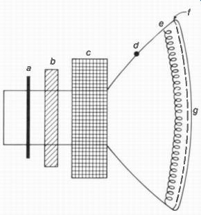
FIGURE 11-17 FOR PROBLEM 5