The dc level in the video signal indicates the difference in brightness between light and dark scenes. Remember that brightness is the average illumination or back ground level. In the picture, a scene may be in bright sunlight or in a dark room at night. For both cases, the details of picture information could be the same, but the brightness level is different.
At the grid of the picture tube, its dc bias voltage determines the brightness.
The manual brightness control can set the dc bias for the correct background with any scene. However, when the background becomes lighter or darker, the dc bias should be different. The dc component of the video signal can shift the dc bias to show the change in brightness. More details are explained in the following topics:
14-1 Changes in brightness
14-2 Definitions of terms for the dc component
14-3 How a coupling capacitor blocks the average dc voltage
14-4 Dc coupling and ac coupling
14-5 Average value of the video signal
14-6 DC insertion
14-7 Video amplifier dc-coupled to picture tube
14-1 Changes in Brightness
A common example occurs when the program goes to black before a commercial or a change of scene. Similarly, the change can be from a bright scene in daylight to a dark scene at night.
If the dc component of the video signal does not shift the bias on the picture tube for less brightness, the reproduced picture will not be dark enough. The opposite effect occurs when the bias is right for a dark scene but the scene changes to a light background. With too much bias for the light scene, whatever should be white becomes gray and the gray tones go black.
With color especially, the dc component of the video signal is needed for correct reproduction of the color values.
The signal is transmitted with its dc component. At the receiver, the dc component is in the varying dc voltage output of the video detector. If the video amplifier has dc coupling, from the detector to the picture tube, the dc component will be preserved. However, capacitive coupling in the video amplifier removes The dc component in the signal.
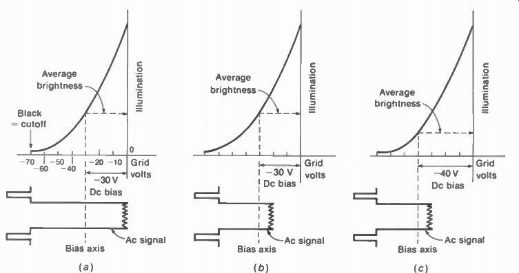
FIGURE 14- 1 HOW DC GRID VOLTAGE OF PICTURE TUBE SETS AVERAGE BRIGHTNESS
FOR LIGHT AND DARK SCENES (a) LIGHT SCENE WITH CORRECT GRID BIAS OF 30 V (b)
BIAS OF 30 V IS TOO FAR FROM CUTOFF FOR DARK SCENE (c) CORRECT BIAS OF 40 V
FOR SAME SIGNAL AS IN b
To be more specific about brightness changes, Fig. 14-1 illustrates the effects of negative dc bias voltages at the control grid of the picture tube. The same idea applies to positive dc bias voltages at the cathode. In terms of the control grid, more negative bias decreases the average brightness. Remember that the dc bias voltage is the axis for the ac video signal variations. The dc bias should be the amount that allows the blanking level in the video signal to swing the grid voltage to cutoff for black.
In Fig. 14-1a, the bias of -30 V is correct for a light scene. The average brightness or background illumination corresponds to a little less than one-half the maximum beam current.
Then the blanking voltage in the video signal drives the grid voltage to cutoff so that the blanking level is black. Also, maximum white in the video signal produces the peak beam current.
In Fig. 14-1b, the dc bias is still -30 V, but the ac video signal corresponds to a darker scene. The fact that this signal is darker is evident from the fact that the signal variations are not so far from the black level, compared with a.
It should be noted that this is not a question of less ac signal, since the sync amplitude is the same in a and b. Now the grid bias of -30 V is not negative enough for the darker scene. As a result, black shows as gray. On the whole, the reproduced picture is not dark enough.
The darker video signal in Fig. 14-lb needs the more negative grid bias of -40 V shown in c. Now the average brightness level is lower for less illumination with a darker back ground. Also, the blanking level is at cutoff for black.
It is important to realize that the change in video signal from a to b or c represents a typical line of information from different frames. Any change in background is a change in signal for the frames, not for the lines. Changes of information from line to line are part of the ac video signal.
FIGURE 14-2 BRIGHTNESS TOO HIGH- BLACK VALUES NOT DARK ENOUGH. VERTICAL RETRACE LINES ARE SHOWN HERE, BUT THEY ARE NORMALLY NOT VISIBLE BECAUSE OF RETRACE SUPPRESSOR CIRCUIT.
Figure 14-2 shows a picture with the brightness too high. The diagonal lines upward to the right are the vertical retrace lines. These lines are produced by the horizontal scan, but during the vertical retrace time. They are visible here because the pedestal level is not at cutoff for blanking. However, normally you would not see them because receivers have retrace suppressor circuits to blank the retrace lines at any setting of the brightness control.
FIGURE 14-3 AVERAGE LEVEL IN THE VIDEO SIGNAL (a) CLOSE TO WHITE (b) CLOSE TO BLACK
14-2 Definitions of Terms for the DC Component
Referring to Fig. 14-3, note the amplitude levels.
The blanking level is at 75 percent. Sync amplitudes are between this level and 100 percent for tip of sync. Maximum white is at 12.5 percent, as an average between 10 and 15 percent.
The black level in picture information is at the 68.5 percent level. This value is 7.5 percent from the blanking level, as an average between 5 to 10 percent. The black setup of 7.5 percent is used to separate very dark picture information from the blanking level, especially in a colorplexed video signal. In studio work with television cameras, the black setup is also called pedestal voltage. The pedestal control to vary the amount of black setup determines the sensitivity to black and dark gray.
The average level in Fig. 14-3 divides the signal amplitudes into equal amounts above and below the axis. In a, the average axis is close to white because the picture information is mostly white, except for the dark bar in the middle. In b, the average axis is close to black because the signal is mostly at the black level. In the ac form of the signal, the average level is the zero axis.
As a fluctuating dc signal voltage, the average axis is a dc level.
Dc insertion. In the transmitted signal, the tip of sync is always at 100 percent amplitude. This is necessary to have a reference amplitude for AGC circuits. The fact that the sync pulses have the same amplitude for light or dark picture in formation means that the transmitter adds a dc component to the average axis. This process is dc insertion. When the receiver adds a dc component after it has been lost by capacitive coupling in the video amplifier, this process is dc reinsertion.
Dc restorer. This is a diode rectifier circuit that has the function of inserting the dc component.
The video signal itself can be rectified to produce a dc voltage proportional to the level of brightness.
Clamping. This term means keeping one amplitude at a constant level. For instance, the blanking level can be clamped at cutoff grid voltage for the picture tube. The clamping function is really the same as dc insertion or dc re-insertion, as a dc component must be added to clamp different ac signal waveforms.
Retrace suppressor circuit. Instead of relying on the blanking in the video signal, receivers provide their own blanking pulses for the picture tube to make sure retrace lines are not visible.
Vertical flyback pulses from the vertical deflection circuit are used to suppress the vertical re-trace lines. Practically all receivers use a vertical retrace suppressor circuit. In addition, horizontal flyback pulses can be used for a horizontal retrace suppressor. Color receivers generally use both horizontal and vertical flyback pulses for blanking.
14-3 How a Coupling Capacitor Blocks the Average DC Voltage
Refer to Fig. 14-4, where C. is a coupling capacitor with its series R to form an RC coupling circuit. The signal applied to terminals 1 and 2 is a pulsating or fluctuating dc voltage. It varies between 10 and 30 V with an average of 20 V. This average value is the steady dc level. The variations of - ±10 V around this axis form the ac component. C,. will charge to the steady dc level of 20 V because this value is the average charging voltage. As a result, the steady dc component is blocked, since it cannot produce voltage across R. The ac component, however, is developed across R between output terminals 3 and 4.
Note that the zero axis of the ac voltage output across R corresponds to the average axis of the fluctuating dc voltage input.
The dc component across C,.. The voltage across C,. is the steady dc component of the input voltage because the variations of the ac component are symmetrical above and below the average level. Furthermore, the series resistance is the same for charge and discharge. As a result, any increase in charging voltage above the average level is counteracted by an equal discharge below the average. In Fig. 14-4, for example, when e,„ increases from 20 to 30 V, this effect of charging C, is nullified by the discharge when e,„ decreases from 20 to 10 V. At all times, however, e,„ has a positive value that charges C,. in the polarity shown.
The net result is that only the average voltage level is effective in charging C,., since the variations from the axis neutralize each other.
After a period of time that depends on the RC time constant, C,. will charge to the average value of the pulsating dc voltage applied, which is 20 V here.
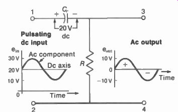
FIGURE 14-4 HOW Cr BLOCKS THE AVERAGE DC LEVEL OF A FLUCTUATING DC VOLTAGE.
The ac component across R. Although C,. is charged to the average dc level, when the pulsating input voltage varies above and below this axis, the charge and discharge current produces IR voltage corresponding to the fluctuations of the input. When e,„ increases above the average level, C,. takes on charge, producing charging current through R. Even though the charging current may be too small to affect the voltage across C,. appreciably, the IR drop across a large value of resistance can be practically equal to the ac component of the input voltage. In summary, a long RC time constant is needed for good coupling.
Polarity of the ac component. In Fig. 14-4, when e,„ is above 20 V, the charging current produces electron flow from the low side of R to the top, adding electrons to the negative side of C,.. The voltage at the top of R is then positive.
When e,„ decreases below the average level, C,. loses charge. The discharge current then is in the opposite direction through R. The result is negative polarity for the ac voltage coupled across R.
When the input voltage is at its average level, there is no charge or discharge current.
Then the voltage across R is zero. The zero level in the ac voltage across R corresponds to the average level of the pulsating dc voltage applied to the RC circuit.
With positive pulsating dc voltage applied, the values above the average produce the positive half-cycles of the ac voltage across R. The values below the average axis produce the negative half-cycles.
Voltages around the RC coupling circuit. If you measure the pulsating dc input voltage across points 1 and 2 in Fig. 14-4 with a dc volt meter, it will read the average level of 20 V. A voltmeter that reads only ac values across these same points will read the fluctuating ac component, equal to 7 V rms.
Across points 1 and 3 for C,., a dc volt meter reads the steady dc value of 20 V. An ac voltmeter here reads zero.
An ac voltmeter for the output across R between points 3 and 4 will read the ac voltage of 7 V rms. A dc voltmeter here reads zero.
There is practically no phase shift. This rule applies to all RC coupling circuits, since R must be 10 or more times X,.. Then the reactance is negligible compared with the series resistance, and the phase angle of less than 5.7 is practically zero.
Once the dc component is blocked by C,., it does not matter how many more capacitive couplings are used. The ac component always has an average axis of zero, which cannot be changed by the coupling. Furthermore, direct coupling in a succeeding stage does not put back the dc component that was blocked. Only a dc restorer circuit can do that.
14-4 DC Coupling and AC Coupling
These terms indicate whether the dc component is coupled with the ac signal. In ac coupling, only the ac signal is coupled, while any dc component is blocked. In dc coupling, both the ac signal and its dc component are coupled to the next stage.
Ac coupling. An RC circuit provides ac coupling for the signal, as the steady dc component is blocked by C,.. A transformer with an isolated secondary winding also blocks the dc component, but this method is not used for coupling the video signal. Transformer coupling is generally used in the rf and IF circuits for the modulated picture carrier signal. However, in these stages, the dc component of the video signal is not affected. The dc component is available only after the modulated signal is detected. The ad vantage of an RC circuit for ac coupling of the video signal is that the dc level of the fluctuating dc voltage in the output of one stage does not affect the dc bias for the input of the next stage.
Dc coupling. This term means a direct connection for the signal, without any series capacitor.
The advantage is that the lowest frequencies are coupled, including the steady dc component.
With direct coupling, however, all the electrode voltages in the amplifier depend on the dc voltages of the previous stage. Any change in supply voltage or dc bias affects all the stages inter connected by dc coupling. A particular problem is drift in the dc supply voltage, which can alter the bias voltages.
Partial dc coupling. See Fig. 14-5. C, is used to couple all the ac video signal. R, and R, form a voltage divider for the dc component. The dc voltage across R, is the dc component for the picture tube. In this example, the voltage across R2 is 8/ i „, or 80 percent, of the total dc voltage.
Typical values are 50 to 80 percent of the dc component for the picture tube, with partial dc coupling.
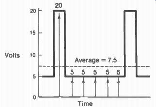
FIGURE 14-6 PARTIAL DC COUPLING. R, HAS 80 percent OF THE DC COMPONENT,
WHILE C, COUPLES ALL THE AC COMPONENT.
FIGURE 14-6 AVERAGE VALUE OF A FLUCTUATING DC VOLTAGE
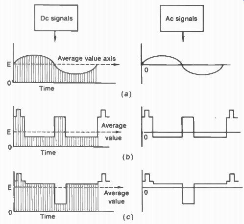
FIGURE 14-7 AVERAGE-VALUE AXIS FOR DIFFERENT WAVEFORMS. DC FORM IS AT LEFT
AND AC FORM AT RIGHT. (a) SYMMETRICAL SINE WAVE WITH AVERAGE AXIS IN CENTER.
(b)
UNSYMMETRICAL VIDEO SIGNAL. MOSTLY WHITE. AVERAGE AXIS IS CLOSE TO WHITE-SIGNAL AMPLI TUDES. (c) UNSYMMETRICAL VIDEO SIGNAL, MOSTLY BLACK. AVERAGE AXIS IS CLOSE TO BLACK LEVEL.
14-5 Average Value of the Video Signal
For any signal, its average value is the arithmetical mean of all the values taken over a complete cycle. With fluctuating dc voltage, the average is some dc level. In Fig. 14-6, as an example, if we add the five values of 5 V each and the 20-V value, the sum is 45 V. The instantaneous dc values are taken from the zero base line. This sum divided by 6 for the values included equals ''/„, or 7.5 V for the average value.
Notice that the average axis of 7.5 V is close to the 5-V level, not in the middle. The reason is that this signal voltage is 5 V for most of the cycle. The average-value axis divides the signal into two equal areas above and below the axis.
When fluctuating dc voltage is coupled by an RC circuit, the average dc axis becomes the zero axis in the ac signal. This idea is illustrated for three types of signals in Fig. 14-7. The sine wave in a has an average-value axis exactly in the center because it is a symmetrical waveform.
In b the video signal corresponds to a black bar down the center of a white frame. Now the average-value axis is closer to white level be cause the signal is white for most of the cycle.
The opposite case in c is for a white bar down the center of a black frame. Then the average value axis is close to black level, because the signal is mostly black.
In all cases the average dc axis becomes the zero ac axis, with equal areas of positive and negative signal above and below the axis. however, notice that for the dark signal in c its axis is much closer to the black level than in b.
If we put the dark and light video signals on a common axis, the sync pulses are out-of line, as shown in Fig. 14-8. The common axis for the signals in their ac form is the zero level. Furthermore, the zero axis of the ac signal corresponds to the dc bias at the grid of the picture tube. When the blanking level has different voltage variations from the common axis, one set ting of the brightness control cannot be correct for both dark and light scenes. The bias illustrated in Fig. 14-8 is right for the light video signal at the top. Then the blanking voltage drives the grid voltage to cutoff. However, for the dark video signal below, the bias indicated is not negative enough. In this case the blanking level is not black, and the dark scene is reproduced too light.
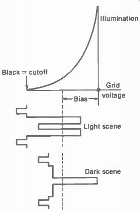
FIGURE 14-8 SYNC PULSES OUT OF LINE AT GRID OF PICTURE TUBE. SHOWN FOR THE
TWO LINES OF VIDEO SIGNAL IN FIG. 14-7b AND C. A SINGLE VALUE OF BIAS CANNOT
BE CORRECT FOR BOTH SIGNALS.
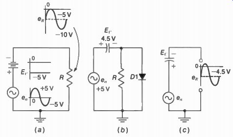
FIGURE 14-9 ILLUSTRATING NEGATIVE DC INSERTION. POSITIVE PEAK OF SIGNAL e„
IS CLAMPED AT ZERO VOLTAGE. (a) BATTERY SUPPLIES DC COMPONENT E, (b) DIODE
RECTIFIES SIGNAL TO PRODUCE E, FOR DCcom PONENT (c) EQUIVALENT CIRCUIT OF
E, IN SERIES WITH e„
14-6 DC Insertion
The basic principle is illustrated in Fig. 14-9a.
Note that the output voltage e k is the sum of the ac generator voltage e„ and the battery voltage E, because they are in series with each other across R. The effect of E, is to shift the entire ac signal to a new axis of -5 V. Although the variations in the ac signal are still the same, they now vary above and below the negative 5-V axis, in stead of the original zero axis.
The output e, is a fluctuating dc voltage of negative polarity. This is negative dc insertion. If the polarity of the battery is reversed, it will produce positive dc insertion. Then the variations will be around a new axis of +5 V. In the waveshape for e R, notice that the positive peak of the ac signal is kept at the zero level, because of the -5 V added by E,.. This idea of shifting the signal axis to keep one point at a fixed voltage level is clamping. In this case, the positive signal peak is clamped at 0 V. Actually the signal can be clamped at any desired level, depending on the amount of dc voltage inserted.
It is more useful to accomplish the dc insertion for clamping by using a diode to rectify the ac signal, as in Fig. 14-9b. The diode D1 is a rectifier to produce dc voltage proportional to the ac signal. When its anode is driven positive by input signal, the diode conducts to charge C. Between signal peaks when D1 does not con duct. C can discharge through the high resistance of R. With an RC time constant very long compared with the time between positive peaks of the signal, C discharges very slowly, compared with the fast charge of diode current. As a result, C accumulates a negative charge, equal to approximately 90 percent of the positive peak of the ac signal. The resulting dc voltage E,. can be considered a dc component in series with the signal, as shown in c.
Positive dc restorer. At the grid of the picture tube, the polarity of the dc insertion is positive, to reduce the negative bias for light scenes. For positive dc insertion in Fig. 14-9, the battery would be reversed in a or the diode inverted in b.
The results are shown in Fig. 14-10. Here the negative peak of ac signal drives the diode cathode into conduction. The diode current charges C with the cathode side positive. Finally, the waveform here shows the negative peak of the signal clamped at zero in the positive dc restorer circuit.
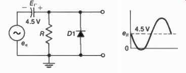
FIGURE 14-10 POSITIVE DC INSERTION WITH DIODE DC RESTORER.
The restored voltage will be clamped for any level of ac signal. If the signal changes, the diode restorer will provide the dc component needed to clamp the signal peak at one level.
For television, the composite video signal is rectified to provide the dc component. Once the dc component has been inserted, direct coupling must be used to keep the dc axis of the signal.
Dc restorer time constant. Differences in brightness level correspond to a shift from a light scene to a dark scene, or vice versa. Such variations occur at a rate lower than the frame frequency of 30 Hz. Furthermore, if the brightness of the scene is constant, there is no change at all in the dc level. Then the manual brightness control could set the correct bias without the need for any dc reinsertion. As an example, when a test pattern is transmitted, the dc level of the video signal is constant.
The reinserted dc voltage should vary from frame to frame when the average brightness changes, but not from line to line. Therefore, the time constant of the dc restorer is very long compared with the horizontal-line period, but not with respect to the frame time. A suit able value is 0.03 to 0.1 s. The RC time constant includes the coupling capacitor for the diode rectifier and the diode shunt resistor.
14-7 Video Amplifier DC-coupled to Picture Tube
The video output stage is often directly coupled to the picture tube, in order to keep the dc component. See Fig. 14-11. In this case, the dc electrode voltages for the video amplifier affect the bias for the picture tube. In fact, trouble in the video amplifier can cut off the picture tube, resulting in no brightness.
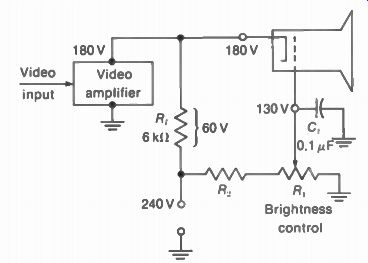
FIGURE 14-11 DC VOLTAGES FOR VIDEO AMPLIFIER directLY COUPLED TO CATHODE
OF PICTURE TUBE
Normal dc voltages. In Fig. 14-11 the cathode bias for the picture is 50 V. This value is the potential difference between 180 V at the cathode and 130 V at the grid. The cathode voltage is the same 180 V as on the video amplifier because of the direct coupling. This 180 V is the result of the 60-V IR drop across R _p from the 240-V supply.
The 130 V at the control grid of the picture tube is set by the brightness control R. This is in series with R2 as a voltage divider across the 240-V supply. The bypass capacitor C, is the ac return for video signal coupled from the video amplifier to the picture tube. The cathode-to grid voltage then is 180 130 50 V. How the picture tube can be cut off by the video amplifier. Suppose that the video amplifier does not conduct. With a tube, the heater can be open. With a transistor, the collector can be open, or there is not enough forward bias. When the video amplifier does not conduct, the result is no IR drop across RI ,. Then the dc voltage at the output of the video amplifier is 240 V. This value is equal to the supply voltage. The cathode voltage at the picture tube is then 240 instead of 180 V. As a result, the cathode-to-grid voltage is 240 - 130 = 110 V. This bias of 110 V will cut off the picture tube.
When the picture tube is cut off, the result is no brightness. Most often, though, the trouble of no brightness is caused by no high voltage. A useful method of distinguishing between the two troubles is to turn the receiver off, after it has been on for a few minutes. The picture tube usually has some afterglow on the screen just after the receiver is turned off, when there is high voltage on the anode. If the trouble is no brightness, but you can see afterglow, then the picture tube is cut off.
SUMMARY
1. The brightness or average background level of the reproduced picture is deter mined by the dc bias for the cathode-grid circuit of the picture tube. More negative bias at the grid or more positive bias at the cathode reduces the brightness.
2. The transmitted signal has a dc component to indicate changes in scene brightness. The dc component clamps the blanking at 75 percent carrier level. In the receiver, this dc component is maintained in the rf and IF amplifiers and is present in the video detector output.
3. In a video amplifier with capacitive coupling, the dc component is blocked. With direct coupling, the dc component is preserved. Partial dc coupling is often used for 50 to 80 percent of the dc component.
4. The dc component in the composite video signal is indicated by how far the average axis is from black level.
5. Dc insertion or reinsertion means adding a dc component to an ac signal for the purpose of keeping one peak at a fixed level. This is also clamping.
6. A dc restorer is a diode that rectifies the signal for dc insertion. A positive restorer inserts positive dc voltage; a negative restorer inserts negative dc voltage.
7. The basic purpose of having the dc component of the video signal for the grid cathode circuit of the picture tube is to clamp the blanking level at cutoff. When black is reproduced correctly, all other light values are correct for different degrees of scene brightness.
8. Receivers have suppressor circuits to blank out retraces, independent of the brightness setting.
9. When the video amplifier is dc-coupled to the picture tube, trouble in the video amplifier can result in cutoff bias for the picture, causing no brightness.
Self-Examination (Answers at back of guide)
Answer True of False.
1. The average dc voltage for the cathode-grid circuit of the picture tube deter mines brightness.
2. When the cathode is 140 V and the grid is at 100 V, the grid bias is -240 V.
3. The correct dc component is always present in the output of the video detector.
4. At the picture tube, the blanking level should be clamped at zero grid-cathode voltage.
5. If you measure the waveshape in Fig. 14-6 with a dc voltmeter, it will read 7.5 V.
6. With an RC coupling circuit, the average dc voltage is across C while the ac component is across R.
7. For the two video signals in Fig. 14-7, the dark signal in c has an average level close to black.
8. In Fig. 14-11, the voltage across the 6-k-o R_L. is 60 V because the current through it equals 10 mA.
9. In Fig. 14-5, if R, were increased to 0.8 M-ohm to equal R2, the dc coupling would be 50 percent.
10. When the picture changes from daylight to a night scene, the average axis moves closer to black level.
Essay Questions
1. What is the effect on brightness when the picture tube has (a) too much positive bias at the cathode; (b) too little bias?
2. What is meant by clamping the blanking level at cutoff for the grid-cathode circuit of the picture tube?
3. A video detector is directly coupled to the video output tube, which is RC-coupled to the cathode of the picture tube. Is the dc component of the video signal present at the picture tube? Why?
4. Referring to the diagram in Fig. 14-11, give the function of R1, R2, and C.
5. In the diagram of Fig. 14-10, give the function of R, C, and D1.
6. Redraw the waveshape in Fig. 14-6 with different amplitudes and show the new average value.
7. Referring to the RC-coupling circuit in Fig. 14-4, how much would a dc voltmeter read across C,. and across R?
8. Define the following: dc insertion, dc restorer, diode clamp, and black setup.
Problems (Answers to selected problems at back of guide)
1. If the waveshape in Fig. 14-6 has a peak value of 30 V and minimum of 6 V, how much will this average value be?
2. Draw an ac sine wave having a peak value of 100 V. Give its amplitudes at 0, 30, 60, 90,120, 150, and 180'. Calculate the average of these values. How much is the average taken over the complete cycle of 360°?
3. A symmetrical square wave of fluctuating dc voltage varies between 180 and 120 V. (a) How much is the average dc level? (b) If this voltage is applied to an RC coupling circuit, how much will E,. be? (c) How much is the peak-to-peak value of the ac voltage across R?
4. Draw the composite video signal waveshapes for one line all white and another line all black, with 5 percent black setup. Calculate the average value of each signal, using 100 V for peak of sync and 10 V for white.
5. For each of the three waveforms in Fig. 14-12, (a) indicate the average dc level; (b) show the ac form with peak-to-peak amplitude.
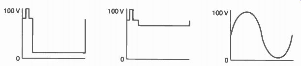
FIGURE 14-12 FOR PROBLEM 5.