These circuits make it much easier to obtain a good color picture. Starting with the rf tuner, the automatic fine tuning (AFT) sets the local oscillator frequency to tune in the color signal. In the chroma circuits, the automatic chroma control (ACC) provides automatic bias for constant output from the color amplifier. Also, the automatic tint control (ATC) shifts the hues toward red for more pleasing flesh tones. Further more, the color killer circuit automatically cuts off the 3.58-MHz chroma section when a monochrome program is received. Finally, the one-button tuning automatically connects preset controls for good contrast, brightness, and color in the picture. The automatic color circuits generally use small transistors and integrated circuit (IC) units, as there is little power involved. An alphabetical listing of the automatic features is given in the summary at the end of this SECTION; the circuits explained here are:
18-1 Color killer and automatic chroma control (ACC)
18-2 Color killer circuit
18-3 Color killer adjustment
18-4 ACC circuit
18-5 Peak chroma control (PCC)
18-6 Automatic tint control (ATC)
18-7 Automatic brightness limiter (ABL)
18-8 One-button tuning
18-1 Color Killer and Automatic Chroma Control (ACC)
For a monochrome picture, the color receiver uses only the amplifiers for Y luminance signal.
The 3.58-MHz chroma bandpass amplifier and chroma demodulators are not needed because there is no color signal to amplify. When the 3.58-MHz color circuits are on without any signal applied, they generate receiver noise. This appears in the picture as color snow or "confetti." In a monochrome picture, crosstalk between the color snow and high-frequency components of the luminance signal produces color sparkle at the edges of black-and-white objects in the scene.
The function of the color killer is to cut off the 3.58-MHz chroma circuits when there is no color signal. Either the bandpass amplifier or the demodulators can be turned off by the color killer. A threshold or level control is provided to adjust the point where the killer circuit automatically cuts off the chroma circuits for a black and-white program.
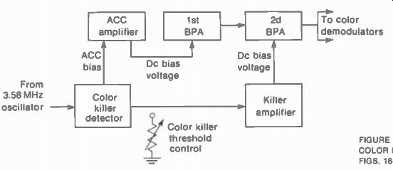
FIGURE 18-1 BLOCK DIAGRAM OF COLOR KILLER AND ACC CIRCUITS IN FiGS. 18-2
AND 18-3.
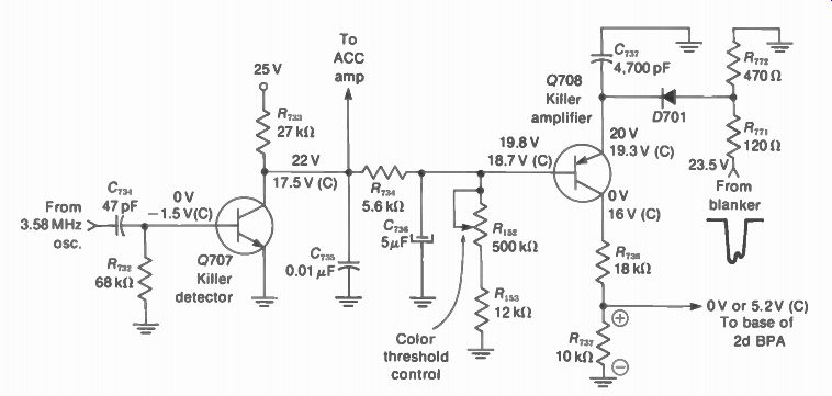
FIGURE 18-2 COLOR KILLER CIRCUIT. VOLTAGES MARKED (C) ARE WITH COLOR SIGNAL.
ACC CIRCUIT IN FIG. 18-3. (FROM ADMIRAL CHASSIS 2K20)
The color killer circuit recognizes a monochrome program by the absence of the color burst signal. Any time there is no separated burst for color synchronization, the color killer will cut off the color amplifier.
Automatic chroma control (ACC) is to the chroma bandpass amplifier as the AGC bias cir cui: is to the picture IF amplifier. The ACC bias varies the gain for the 3.58-MHz bandpass amplifier inversely as the strength of the received color signal. The signal strength is determined from the relative amplitude of burst. More burst means more color signal, which needs less gain in the bandpass amplifier. As a result, the ACC circuit maintains a constant color level in the picture when changing stations.
The color killer and ACC circuits usually function together, as illustrated in Fig. 18-1. The reason is that they both depend on the 3.58-MHz color sync burst transmitted on the back porch of the horizontal blanking pulses. Burst amplitude determines the ACC bias. No burst at all means the color killer operates to cut off the color amplifier.
In Fig. 18-1, the amount of 3.58-MHz oscillator cw input to the killer detector depends on the burst input to the oscillator. The defector rectifies this ac input to produce a dc bias voltage. For the killer, the bias is amplified to cut off the second bandpass amplifier. For the ACC circuit, the bias is amplified to control the gain of the first bandpass amplifier.
18-2 Color Killer Circuit
In Fig. 18-2, the signal from the 3.58-Mhz oscillator is coupled to the base of the killer detector Q707 by C7:{,. The oscillator operates all the time, but its output is not large enough to turn on Q707 until a color signal is received. Burst input causes the amplitude of the color oscillator to increase. Now the positive half-cycles of the oscillator output will turn on Q707. The signal is rectified by the base-emitter diode of the transistor, producing a signal bias of -1.5 V. Then only the positive tips of the signal produce /, in Q707. The resulting average /, causes the collector voltage to drop from 22 V to 17.5 V. A voltage divider from the collector of Q707, through R7 „ _p and Ri53 , determines the base voltage of Q708. When the collector voltage of Q707 decreases, the base voltage of Q708 also goes less positive and Q708 turns on. Note that Q708 is a PNP transistor drawn with the emitter at the top. The N base needs negative forward bias.
The emitter voltage of Q708 is at a relatively constant value from the blanker circuit.
When Q708 conducts, it produces a voltage drop of 5.2 V across F17„7 in the collector circuit.
The IR drop has positive polarity with a PNP transistor. This voltage is applied to the base terminal on the second bandpass amplifier to allow conduction. In short, the killer detector, amplifier, and bandpass amplifier are all on for a color program with burst signal into the color oscillator.
When there is no burst signal, the killer detector Q707 is off. Then the amplifier Q708 is also off because it does not have enough forward bias at the base. With Q708 not con ducting, its collector is at 0 V. The absence of 5.2 V for the base of the bandpass amplifier cuts it off.
18-3 Color Killer Adjustment
In Fig. 18-2, the base voltage on the killer amplifier Q708 is set by the variable resistance R. This is the color threshold or color killer control. It is set here at 19.8 V for no color. With the base at 19.8 V and the emitter at 20 V, the net bias equals 0.2 V. This is not enough forward voltage for the silicon transistor, which needs approximately 0.6 V base-emitter bias for conduction.
As a result, Q708 is off, its collector voltage is zero, and the base of the second bandpass amplifier is cut off.
In general, the color threshold or killer control is adjusted as follows:
1. Select an unused channel.
2. Set the color level to maximum.
3. Adjust the control until color snow appears on the screen. Back off the control slightly until the snow just disappears.
4. Check all channels to be sure color is on for all color programs. If not, readjust the control slightly.
The color killer control should be set at the threshold point, even though it can cut off color for a wider range of settings. This adjustment can have an important effect on how the color is tuned in by the fine tuning control without the 920-kHz beat. If the color cuts out too soon, the correct tuning is more difficult.
18-4 ACC Circuit
In Fig. 18-3, the amplitude of the chroma signal is controlled by using automatic bias from the ACC amplifier to vary the gain of the first bandpass amplifier. Q709 is a dc amplifier for the ACC bias. Its input is dc voltage from the collector of the killer detector Q707, shown in Fig. 18-2. Remember that this collector voltage varies with the amount of oscillator signal, which in turn depends on burst amplitude. More signal causes more conduction in Q707, reducing the collector voltage. Then the input to the base of Q709, through R7 „„, goes less positive.
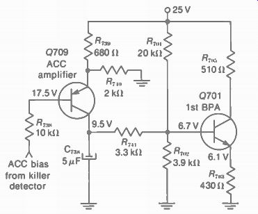
FIGURE 18-3 ACC CIRCUIT FOR THE RECEIVER IN FIG. 18-2.
Note that Q709 is a PNP transistor, with the emitter shown at the top. The emitter voltage is determined by R73„ and R74„ from the 25-V supply. When Q709 has base voltage of 17.5 V with color signal, the base-emitter voltage is 17.5- 18.2 = -0.7 V. This forward bias then enables the ACC amplifier Q709 to conduct.
With Q709 conducting, its collector current produces an IR drop across R7 . This increase in positive base voltage for the NPN transistor allows Q701 to conduct. The base voltage on the bandpass amplifier then varies in accordance with the strength of the color signal to control the gain.
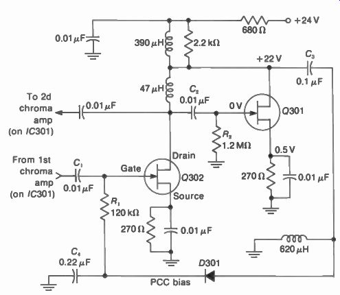
FIGURE 18-4 PEAK CHROMA CONTROL (PCC) CIRCUIT. Q301 AND Q302 ARE JUNCTION
FIELD-EFFECT TRANSISTORS. (FROM SEARS MODEL 4360)
18-5 Peak Chroma Control (PCC)
This circuit can be compared with delayed AGC, in that the control bias is not developed until the signal reaches a specific amplitude. Another name is color overload control. When the chroma amplitude exceeds a maximum level, the PCC circuit clips the peaks of the signal. As long as the chroma is below this point, though, the PCC circuit functions only as a chroma amplifier.
In Fig. 18-4, Q301 and Q302 are junction field-effect transistors. The channel is N-type, which requires negative voltage for reverse bias at the gate. This operation is similar to negative grid bias without grid current for a triode tube.
Q302 is the PCC amplifier. Q301 supplies chroma signal for diode D301. Its rectified signal is the bias feedback to Q302.
The chroma signal, already amplified by the first color amplifier, is coupled through C, to the gate of Q302. Operating class A, this stage amplifies the signal and couples it back to the second color amplifier in the /C301 unit, not shown here. However, the output signal from the drain of Q302 is also coupled by C2 to the gate of 0301. Then this signal is coupled through C, to the rectifier D301. The diode rectifies the signal to produce negative voltage that is the operating bias for the gate of Q302. C, with R, filters the rectified signal to provide a dc bias voltage.
The bias on Q302 results from rectified chroma signal. Therefore, the bias changes in value with the signal amplitude. Still, this does not affect Q302 as an amplifier until the chroma amplitude reaches a value high enough to cause excessive color saturation. At this point, the bias on Q302 is negative enough to make it clip the signal peaks. The clipping continues until the chroma amplitude drops. In this way, the peak chroma signal is limited to a specific maximum value.
18-6 Automatic Tint Control (ATC)
In many cases, the hue has to be adjusted for proper flesh tones in the picture. Most people prefer more red. Also, the hue can change slightly for different programs because of a shift in burst phase. The ATC circuit compensates for these problems by automatically emphasizing the red hues. Two methods used are: (1) reduce the gain for blue in the color video amplifier; (2) shift the axis of the blue demodulator closer to the phase angle of red.
Referring to Fig. 18-5, Q6 is used as a gate and Q7 is a solid-state switch. If Q6 is to con duct, it must have the proper ACC voltage input and the Instamatic switch must be in the automatic position. Then the base of Q6 is at 7.4 V, with the emitter at 8 V. This bias of 0.6 V on the PNP transistor allows collector current. As a result, the base of Q7 is at 0.7 V. which drives this NPN transistor into saturation.
The low resistance of the conducting switch Q7 now provides the effect of ground on C. in the base circuit and R. in the collector circuit. Grounding C. changes the demodulation angle for blue, shifting the output to more red.
In addition, grounding one end of R„, puts it in parallel with the emitter resistance of the red video stage, not shown here. This change in emitter bias shifts the dc voltage for the red gun of the picture tube. The background bias and gray-scale tracking are then shifted toward red.
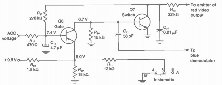
FIGURE 18-5 AUTOMATIC TINT CONTROL. WITH 07 USED TO CONTROL THE PHASE ANGLE
OF THE BLUE DEMODULATOR. (FROM MOTOROLA CHASSIS TS938)
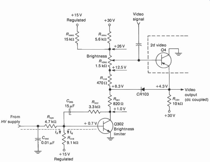
FIGURE 18-6 AUTOMATIC BRIGHTNESS LIMITER CIRCUIT. (FROM RCA CHASSIS CTC-59)
18-7 Automatic Brightness Limiter (ABL)
A number of different methods are used to control brightness. Some maintain a constant brightness despite changes in ac line voltage.
Others hold the brightness constant despite large changes in the average CRT anode current, as would occur when the scene changes from day to night. The circuit of Fig. 18-6 does both.
The base voltage for the video amplifier Q4 is the dc voltage at the variable arm of the brightness control R4202. This voltage controls the emitter current of Q4 and the average voltage drop across R330. Therefore the dc level of the video output signal is controlled.
Since the signal is dc-coupled to the three cathodes of the picture tube, the dc level deter mines the average beam current and therefore the brightness. The end result is that when the base of Q4 goes more positive, its emitter voltage and the cathode voltage on the CRT also go more positive to decrease the brightness. Note that Q4 is a PNP transistor.
Any change in ac line voltage will affect the voltage at the top end of the brightness control. This voltage is approximately +26 V, derived from the voltage divider with R,„ and R„„,. One end of the divider is connected to +15 V. regulated. The other end is connected to the +30-V output of the low-voltage power supply. If the ac line voltage changes, the +30-V line will also change, but the regulated 15 V will not. An increase in line voltage would tend to increase brightness. However, the effect is also more positive voltage at the top of the brightness control. This makes the base of Q4 more positive to decrease the brightness. When the circuit is operating properly, the decreased brightness from Q4 will exactly offset the increase due to line voltage and no change will actually occur.
Assume 26 V at the top of the brightness control. Now the base voltage of Q4 is determined by the current through the control R4202.
This current is the I_c of Q302. More current through the brightness control makes the Q4 base less positive and results in more brightness; less current through the brightness control means less brightness. Therefore, the collector current of Q302 is directly proportional to CRT brightness.
Normally, Q302 is saturated, resulting in maximum brightness for that position of R ,. This transistor is a brightness limiter. Its purpose is not to increase brightness, but rather to decrease it when necessary, to prevent blooming in the picture.
The collector current of Q302 is determined mainly by its base voltage because the emitter is grounded. Collector voltage has little effect on I_c . The base voltage is 0.7 V because of the 14.3-V drop across R319 Its current is the sum of two others: the base current of Q302 and the CRT beam current from the high-voltage power supply through R320. Normally, the sum of these two currents is the required amount.
However, if the CRT beam current changes, the base current on Q302 will change and the brightness is affected.
The integrator circuit of C305 and R332 connected between base and collector of Q302, prevents the circuit from responding to rapid changes in brightness level. If the circuit responds too fast, it could reduce the white high lights in the scene. By responding more slowly, it changes only when the high beam current persists long enough to represent a true change in average level.
The diode CR103 is normally off. It con ducts only if the emitter of Q4 goes more positive than the cathode of CR103. As a result, the diode limits the positive emitter voltage on Q4.
18-8 One-Button Tuning
This feature makes operation of the color receiver very simple. You push the button in and a multipurpose switch does all or most of the following:
1. Sets contrast to a preset level for Y video.
2. Sets brightness to a preset level for cc bias voltage.
3. Sets color level to a preset gain for chroma signal.
4. Sets hue or tint to a preset phase.
5. Turns on automatic tint control (ATC) circuit.
6. Turns on automatic fine tuning (AFT) circuit for local oscillator on rf tuner.
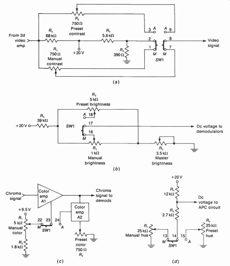
FIGURE 18-7 CIRCUITS FOR ONE-BUTTON TUNING. SW1 IS THE INSTAMATIC SWITCH
THAT CHANGES FROM MANUAL TO PRESET CONTROLS. (a) CONTRAST; (b) BRIGHTNESS;
(c) COLOR LEVEL OR INTENSITY. (d) HUE OR TINT. (MOTOROLA INC.)
Four of these functions are illustrated by the circuits in Fig. 18-7. In addition, a 6.3-V indicator light is turned on by the switch. When the preset adjustments have been made correctly, the one-button tuning automatically results in a good color picture, regardless of the settings of the manual controls.
Preset contrast. Figure 18-7a shows that SW1 changes the output connection for video signal from potentiometer control R, to 131. The switch is shown in the manual (M) position for R _p the manual contrast control. Video signal is applied across R _p with one end grounded by 1 and 2 on the switch, through R. The amount of video signal set by the wiper contact on R, is coupled out through 7 and 8 on the switch.
When SW1 is turned to the automatic (A) position, it moves up in the diagram, joining 2 to 3 and 8 to 9. Then the preset contrast control R., is grounded through R3 while R1 is disconnected. Also, the wiper arm of R, is connected to the output through 8 and 9 on the switch.
The preset control R, has previous y been adjusted for strong contrast without overload distortion. Therefore, the switch automatically provides the proper contrast in the picture.
Preset brightness. For the circuit in Fig 18-7b. the bias on the picture tube is determined by a dc voltage applied to the color demodulator IC unit. These circuits are dc-coupled to the CRT.
Note that terminals 16 and 17 on SW1 select a dc voltage from the manual brightness control R. When the switch is moved up, the preset control R. is connected through 17 and 18. The master control R3 is used to set the maximum bright ness just below the point of blooming, for either the manual or the preset adjustment.
Preset color level. The color intensity or saturation depends on the amplitude of the 3.58-MHz chroma signal. In Fig. 18-7c the gain of the color amplifier A1 is controlled by dc bias from the manual control R. In the automatic position, though, SW1 disconnects R. Then the gain of A1 is controlled by A2. This stage, in turn, has bias from the preset color control R. Preset hue or tint. For the circuit in Fig. 18-7d, the 3.58-MHz color oscillator and its automatic phase control (APC) circuit are in an IC color processor unit, not shown here. Only an external dc voltage for the IC unit is needed to change the oscillator phase, which determines hue or tint. The 20-V source feeds a voltage divider with R3, R _p and either of the hue controls. For manual control, R, is connected to the voltage divider through 13 and 14 on SW1. For the preset hue or tint, R, is connected to the voltage divider through 14 and 15 on the switch.
In addition to connecting the preset controls, the one-button tuning turns on the ATC and AFT circuits. As a result, the ATC circuit shifts the tint for more red and less blue. The AFT circuit provides automatic fine tuning, to tune in the color exactly without 920-kHz beat in the picture.
SUMMARY
The following alphabetical list of abbreviations includes the main types of automatic color circuits. Also included are symbols often used for the circuits in color receivers.
ABL is automatic brightness limiter. It controls bias on the picture tube.
ACC is automatic chroma control. It determines bias on the 3.58-MHz color amplifier.
ADG is automatic degaussing. It demagnetizes the picture tube when the receiver is turned on or off (see Section 11). AFC is automatic frequency control on an oscillator.
AFPC is automatic frequency and phase control.
AFT is automatic fine tuning. It is AFC on the local oscillator in rf tuner (see Section 24). APC is automatic phase control on the color oscillator for hue or tint.
ATC is automatic tint control. It shifts hues toward red.
BPA is bandpass amplifier for the 3.58-MHz chroma signal.
C is 3.58-MHz chrominance, chroma, or color signal.
CK is color killer. It cuts off BPA with monochrome signal.
CO is color oscillator. It regenerates the 3.58-MHz subcarrier for color demodulators.
FET is field-effect transistor.
IC is integrated circuit.
Instamatic is a trademark for one-button tuning.
OBT is one-button tuning (see Fig. 18-7).
PCC is peak chroma control. It clips the peaks of the chroma signal to prevent overload distortion.
Videomatic is a trademark for automatic control of brightness, contrast, and color ac cording to viewing light in the room.
Self-Examination (Answers at back of guide)
Answer True or False.
1. The color killer can cut off the bandpass amplifier.
2. The ACC circuit controls the gain of the chroma amplifier.
3. The ABL circuit prevents blooming in the picture.
4. Changing the phase of the color oscillator changes hue or tint.
5. Changing the gain of the chroma amplifier changes color level or saturation.
6. A PNP transistor needs positive base voltage for forward bias.
7. In an FET, the gate corresponds to the base of a junction transistor.
8. The ATC circuit shifts the tint toward more blue.
9. In one-button tuning, the contrast, brightness, and color intensity are set to preset levels.
10. The color sync burst is needed for operation of the color killer and ACC circuits.
Essay Questions
1. List five abbreviations for automatic color circuits and give their functions.
2. Give the function of the color killer circuit.
3. Explain how to set the color killer threshold control.
4. Which stages determine color intensity or saturation?
5. Which stages determine hue or tint?
6. Referring to Figs. 18-2 and 18-3, give the specific functions for Q707, Q708, Q709, and Q701.
7. What is meant by blooming in the picture and what is the cause?
8. List at least five functions of one-button tuning.
9. Referring to Fig. 18-7, give the specific connections of SW1 in a, b, c, and d for one-button tuning.