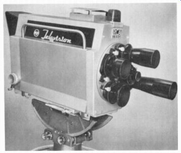
The video signal for the picture begins at the camera tube, inside the camera head (Fig. 3-1). The input is light from the scene to be televised, and the output is electric signal corresponding to the picture information.
Operation of a camera tube is illustrated in Fig. 3-2. This applies the same way to monochrome or the red, green, and blue camera tubes for color television. Light from the scene is focused by the lens onto the photoelectric image plate. If you could look in, you would see the optical image. The photoelectric properties of the image plate then convert the different light intensities into corresponding electrical variations. With an electron beam scanning across the image plate, line by line, and field by field, the camera signal is produced for the entire picture area. After the camera signal is processed, with sync and blanking added, the result is composite video signal that can be transmitted to the receiver. The main types of camera tubes, in their order of development, are the image orthicon shown in Fig. 3-8, the vidicon in Fig. 3-9, and the plumbicon in Fig. 3-12. More details are described in the following topics:
3-1 Camera-tube requirements
3-2 Image orthicon
3-3 Vidicon
3-4 Plumbicon
3-5 Silicon target plate
3-6 Solid-state image sensor
3-7 Spectraflex color camera tube
3-8 Television cameras
3-9 Definitions of light units
FIGURE 3-1 MONOCHROME TELEVISION CAMERA WITH LENSES OF DIFFERENT FOCAL LENGTHS
ON REVOLVING TURRET (RCA)
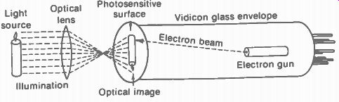
FIGURE 3-2 TELEVISING AN IMAGE WITH VIDICON CAMERA TUBE. EXTER NAL COILS
FOR FOCUSING AND DE FLECTING THE ELECTRON SCANNING BEAM ARE NOT SHOWN.
3-1 Camera-Tube Requirements
First, the image plate must be photoelectric to convert variations of light intensity into electrical variations. In photoemission, electrons are emitted; more light produces more electrons. In photoconduction, the conductance or resistance is changed; more light decreases the resistance. The image orthicon operates by photoemission, while the vidicon and plumbicon depend on photoconduction to produce the required camera signal. A third possibility is the photovoltaic effect, where light on a semiconductor junction can generate a potential difference.
In addition to the photoelectric conversion, scanning of the image plate is necessary to provide signal variations in a successive order, from left to right and top to bottom. The scanning process dissects the image into its basic picture elements. Although the entire image plate is photoelectric, its construction isolates the picture elements so that each discrete small area can produce its own signal variation.
Photoemission. Certain metals emit electrons when light strikes the surface. These emitted electrons are called photoelectrons, and the emitting surface is a photocathode. Especially sensitive to light are the elements cesium, silver, sodium, potassium, and lithium, in the group of alkali metals. Cesium oxide is often used because its photoemission is sensitive to incandescent light. The photoelectric effect is illustrated in Fig. 3-3.
The explanation of the photoelectric effect is that light consists of small bundles of energy called photons. When photons collide with electrons at or near the surface of the photocathode, they give off energy. The energy is used in forcing electrons to escape. The amount of emitted electrons depends on the light intensity. The maximum velocity of the photoelectrons depends only on the wave length of light, however, which is its color. This factor is why a camera tube has different sensitivities for colors in the light spectrum.
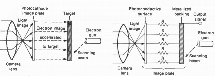
FIGURE 3-3 PHOTOEMISSION PRODUCING AN ELECTRON IMAGE IN A CAMERA TUBE

FIGURE 3-4 PHOTOCONDUCTIVITY OF IMAGE PLATE IN A CAMERA TUBE.
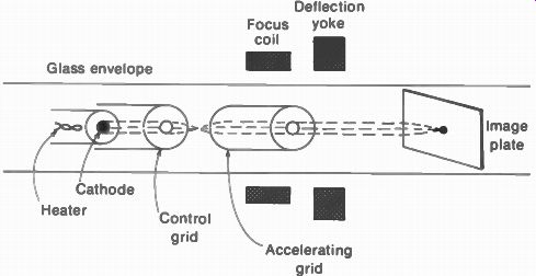
FIGURE 3-5 ELEMENTS OF AN ELECTRON GUN, ILLUSTRATED FOR VIDICON CAMERA TUBE
Photoconductivity. This photoelectric effect is a decrease in resistance with more light. In general, the semiconductor metals including selenium, tellurium, and lead, with their oxides, have this property. The vidicon and plumbicon cam era tubes use an image plate that is a thin photoconductive layer. This function is illustrated in Fig. 3-4. For the vidicon, as an example, the resistance of the photoconductive image plate can decrease from 20 M-ohm for black to 2 M-ohm for white. A disadvantage, compared with photoemission, is that photo-conducting materials generally have a slight lag in the buildup and decay of resistance when the light intensity changes.
The electron scanning beam. An electron gun produces a narrow beam of electrons for scanning. In camera tubes, the electron beam scans the image plate or target plate; in picture tubes, the electron beam scans the fluorescent screen. Enclosed in a vacuumed glass envelope, the gun assembly has a heater, cathode, control grid, and one or more accelerating grids (Fig. 3-5). Since the electrons emitted from the cathode must be concentrated in a beam, the grid structures are in the form of metal cylinders with a small pinhole, or aperture. The control grid voltage determines the amount of beam current, while the accelerating grid attracts the electron beam toward the surface to be scanned.
The gun supplies the electron beam, but the scanning is produced by horizontal and vertical coils in the deflection yoke around the glass neck. In addition, focusing of the electron beam into a small, sharp spot is accomplished by an external focusing coil. This is magnetic focusing, but electrostatic focusing can be used in stead, by varying the voltage on an accelerating grid. Camera tubes generally use magnetic focusing while picture tubes often use electro static focusing. Magnetic deflection with an external deflection yoke is used for both camera tubes and picture tubes.
Optical lenses. With the smaller vidicon and plumbicon camera tubes having a diameter of 1.25 in., the camera can use the same lenses as in 16-mm photography. The focal lengths are generally 4 to 8 in. for wide-angle views and closeup shots. Shorter lenses have a wider angle of view. A typical lens opening is f/5.6 for normal light levels. Lens shades are generally used to reduce reflections (Fig. 3-1). In addition to the different lenses, several cameras can be used for different angles in televising the scene.
The optical lens inverts the image for the camera tube, as shown in Fig. 3-6. Inversion means the image is reversed left to right and top to bottom. Then the image is scanned starting at the bottom right corner of the image plate, corresponding to top left in the scene.
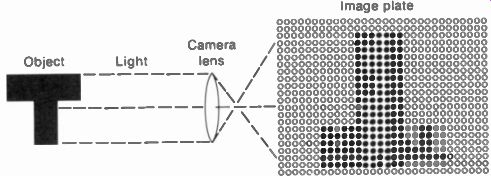
FIGURE 3-6 INVERSION OF PICTURE ON IMAGE PLATE OF CAMERA TUBE
Light splitters. An electron scanning beam is the same in any camera tube or any picture tube.
What happens in the color camera is that the red, green, and blue components of the incident light are separated by optical prisms or by dichroic mirrors. Then each camera tube has light input proportional to the intensity of each primary color in the scene. For instance, the red camera tube has light only for the red parts of the picture. Then its output is red video signal for this component of the color information.
Similarly, the blue and green camera tubes produce blue and green video. Each color video signal is just a sequence of electrical variations, but they represent the intensities for that particular color.
Figure 3-7 illustrates the principles of a four-way beam splitter. The achromatic mirrors shown reflect light of all colors. The dichroic mirrors are coated to transmit light of only one color and reflect the other colors. In Fig. 3-7, light from the lens on the turret is split into two separate beams. One of these beams is transmitted into the Y, or monochrome, channel. The other beam is reflected into a color-beam split ter. In this arrangement, the white-light beam is reflected through a relay lens onto a set of dichroic mirrors, A and B. These mirrors are mounted on opposing 45 angles. Each mirror is coated to reflect light of one particular color while allowing light of all other colors to pass straight through. In the figure, mirror A reflects red light into the red channel. However, green and blue light pass through to mirror B. Here the blue light is reflected, and the green light passes through. In this way, each camera tube has light input only for its respective color.
It should be noted that a three-way beam splitter is used in color cameras with three cam era tubes. In this case, the Y luminance signal is derived as a combination of the red, green, and blue video signals. There are also color cameras with two camera tubes or even one camera tube.
A single color tube must have a special image plate for the colors, or a motor-driven color wheel rotates in front of a conventional camera tube. This is a sequential arrangement that must be converted to the standard NTSC color signal for broadcasting.
Development of camera tubes. After the mechanical scanning disks were discarded, television broadcasting used the image dissector as the first camera tube, invented by P. T. Farnsworth. The next successful camera tube was the iconoscope, invented by V. K. Zworykin.
This was the first camera tube to use the principle of allowing light to accumulate charge on the image plate. The result is the equivalent of light storage to increase camera sensitivity.
The light sensitivity is the ratio of signal output to the incident illumination. High camera sensitivity is necessary to televise scenes at low light levels.
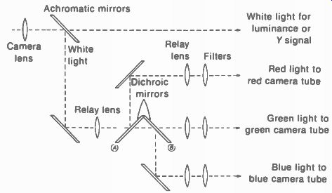
FIGURE 3-7 BEAM SPLITTER FOR THE LIGHT INTO A COLOR CAMERA --- White light
for luminance or Y signal Red light to red camera tube Green light to green
camera tube Blue light to blue camera tube
Next to be developed was the image orthicon (1.0.) camera tube. The 1.0. has high sensitivity but is relatively large. The simplest and smallest camera tube is the vidicon. Similar to the vidicon is the plumbicon camera tube.
This camera tube uses a different image plate made of lead monoxide ( PbO). In later types of vidicons the target plate is an array of many tiny silicon photodiodes.
Another type of camera pickup is the flying-spot scanner. The spot of light from a cathode-ray tube scans a film image, and the light variations are picked up by a photoelectric tube on the opposite side. This method is seldom used anymore because of its size and complexity.
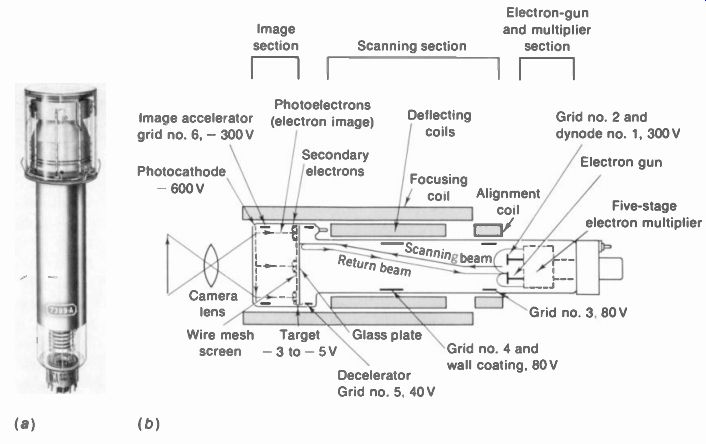
FIGURE 3-8 IMAGE ORTHICON CAMERA TUBE. LENGTH IS 15 IN. (a) PHOTO. (b) CON
STRUCTION AND OPERATING VOLTAGES. (RCA)
3-2 Image Orthicon
As shown in Fig. 3-8, the image orthicon (1.0.) is constructed in three main sections: the image section, scanning section, and electron multiplier. Light from the scene to be televised is focused onto the photocathode in the image section. This action produces a photoelectric image, which is then converted to an electrical charge image on the target plate. One side of the target plate receives the electrons emitted from the photocathode, while the opposite side of the target is scanned by the electron beam from the scanning section. As a result, signal current for the entire image is produced by the scanning beam. The signal current is then amplified in the electron-multiplier section, which provides the desired camera output signal.
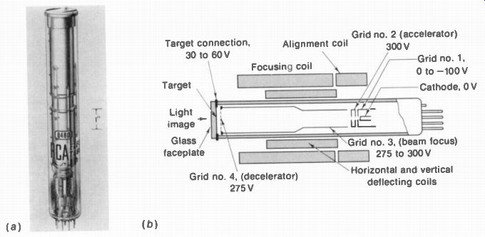
FIGURE 3-9 VIDICON CAMERA TUBE (a) PHOTO. (lb) CONSTRUCTION AND OPERATING
VOLTAGES. (RCA)
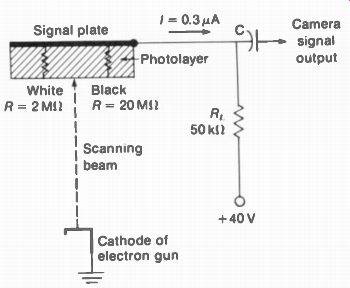
FIGURE 3-10 CIRCUIT FOR CAMERA SIGNAL OUTPUT OF VIDICON.
Producing the camera signal output. The signal action in the image orthicon can be summarized briefly as follows:
1. Light from the televised scene is focused onto the photocathode, where the light image produces an electron image corresponding to the picture elements.
2. The electron image is accelerated to the target to produce secondary emission from the glass plate.
3. The secondary emission produces on the target a pattern of positive charges corresponding to the picture elements in the scene. White is most positive.
4. The low-velocity scanning beam from the electron gun provides electrons that land on the target to neutralize the positive charges.
Scanning-beam electrons in excess of the amount needed to neutralize the positive charges turn back from the target and go toward the electron gun.
5. As the beam scans the target, therefore, the electrons turned back from the glass plate provide a signal current that varies in amplitude in accordance with the charge pattern and the picture information. The signal current is maximum for black.
6. The returning signal current enters the electron multiplier, where the current is amplified. The amplified current flowing through the load resistor in the multiplier's anode circuit produces the camera signal output voltage.
With a signal current of 5 µA from the highlights in the scene and a 2040 R, as typical values, the camera signal output is 100,000 µV. or 0.1 V. A typical dark signal current is 30 µA for 0.6 V across RI .. The peak-to-peak camera signal voltage, then, is 0.6 - 0.1 = 0.5 V.
Sticking picture. The sticking picture is an image of the televised scene with reversed black and white, which remains after the camera has been focused on a stationary bright image for several minutes, especially if the image orthicon is operated without sufficient warmup. The sticking picture can usually be erased, however, by focusing on a clear white screen or wall.
3-3 Vidicon
As shown in Fig. 3-9, the vidicon is a very small camera tube of relatively simple construction.
Figure 3-10 shows the circuit for camera signal output. The vidicon has just a photoconductive target plate and electron gun. With the optical image focused on the target, it produces a charge image that is scanned by the electron beam from the gun. Vidicons are 5 to 8 in. long, with a diameter of 0.58 to 1.6 in. The 3/ 4-in. vidicon is commonly used for closed-circuit television. Average illumination required is about 150 footcandles in the scene or 1 to 10 footcandles on the target plate.
Target. The target has two layers. One is a transparent film of conducting material, coated directly on the inside surface of the glass faceplate. This conductor is the signal-plate electrode for camera output signal. Light passes through to the second layer. which is an extremely thin coating of photoconductive material. Either selenium or antimony compounds are used. The photoconductive property means that its resistance decreases with the amount of incident light.
Charge image. The photolayer is an insulator with a resistance of approximately 20 M-O for the 0.00003-in, thickness, in the dark. Incident light can reduce the resistance to 2 M-O, as indicated in Fig. 3-10. Note that the image side of the photolayer contacts the signal plate at a -4-40 V potential with respect to the cathode. The opposite side returns to cathode through the electron beam, which has an approximate resistance of 90 M-O. With an image on the target, the potential of each point on the gun side of the photolayer depends on its resistance to the signal plate at +40 V. As examples: a white area with low resistance can be close to the signal-plate voltage, approximately at +39.5 V; the potential of a dark area with high resistance is lower at +35 V. The result then is a pattern of positive potentials on the gun side of the photo layer, producing a charge image corresponding to the optical image. Maximum white in the picture is most positive in the charge pattern.
The charge image on the target plate is scanned by the electron beam from the gun.
Electron gun. As shown in Fig. 3-9, the gun includes a heated cathode, control grid (no. 1), accelerating grid (no. 2), and focusing grid (no. 3). The electrostatic field of grid 3 and the magnetic field of an external-focus coil are both used to focus the electron beam on the target plate. Deflection of the beam for scanning is produced by horizontal and vertical deflection coils in an external deflection yoke.
Note that grids 3 and 4 are connected internally. Grid 4 is a wire mesh to provide a uniform field near the target plate. Since the target is at a lower potential of 30 to 60 V, compared with 275 V on grid 4, electrons in the beam are decelerated just before they reach the target plate. The lower potential is used to slow down the electrons so that the low-velocity beam can deposit electrons on the charge image without producing secondary emission from the photo layer.
Signal current. Each point in the charge image has a different positive potential on the side of the photolayer toward the electron gun. Electrons in the beam are then deposited on the photolayer surface, reducing the positive potential toward the cathode voltage of zero. Excess electrons not deposited on the target are turned back, but this return beam is not used in the vidicon.
Consider a white picture element in the charge image on the photolayer. Its positive potential is close to the 40 V on the signal plate just before the electron beam strikes. Then, as electrons are deposited, the potential drops toward zero. This change in potential causes signal current to flow in the signal-plate circuit, producing output voltage across R_L. For black in the picture, where the photolayer is less positive than white areas, the deposited electrons cause a smaller change in signal current.
The signal current results from the changes in potential difference between the two surfaces of the photolayer. The path for signal current can be considered a capacitive circuit provided by 5 pF capacitance of the signal plate to the electron gun. Considering polarity, the output signal produces the least positive or most negative voltage output across R_L. for white highlights in the image. With 1-footcandle illumination on the target, white highlights can produce 0.3-µA signal current for a voltage drop of 0.015 V across the 0.05-M-O load resistor.
Light-transfer characteristics. Three curves of vidicon output current are shown in Fig. 3-11.
Each is for a specific value of dark current, which is the output with no light, corresponding to black in the picture. The dark current is set by adjusting target voltage. Sensitivity and dark current both increase as the target voltage is increased. Typical output for the vidicon is 0.4 µA for white highlights, with a dark current of 0.02 A. Lag. This term refers to the time lag of the photoconductive layer. The lag can cause smear, with a tail or comet following fast-moving objects in the scene. Also, an x-ray appearance, as you seem to be able to see through objects, can be caused by the lag. The photoconductive lag increases at high target voltages, where the vidicon has its best sensitivity. The lag is most troublesome, at low light levels, therefore, when the target voltage is increased for more signal current.
Special types for low lag are: Lead oxide vidicon. This tube has a target plate made of PbO, similar to the plumbicon described in Sec. 3-4.
Silicon-diode vidicon. This tube has a target plate made of silicon photodiodes, as described in Sec. 3-5.
------------------- Illumination: Uniform over photoconductive layer; scanned area of photoconductive layer 1/2" x faceplate temperature = 30°C approx.
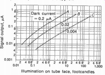
FIGURE 3-11 LIGHT-TRANSFER CHARACTERISTICS OF VI DICON. (RCA)
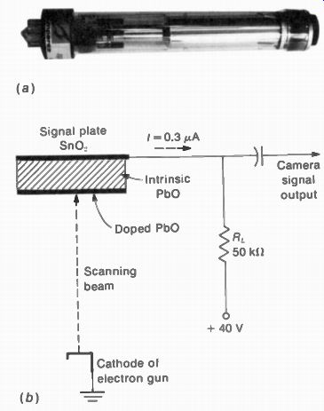
FIGURE 3-12 PLUMBICON CAMERA TUBE LENGTH IS 8 IN (NORTH AMERICAN PHILIPS
COMPANY INC.)
--------------------------
3-4 Plumbicon
As shown in Fig. 3-12, this is a small camera tube like the vidicon. The electron gun is essentially the same as for the vidicon shown in Fig. 3-9.
However, the plumbicon has a new type of target using lead* monoxide ( PbO) for the photoconductive plate. The plumbicon target operates effectively as a PIN semiconductor diode coating on the inner surface of the glass faceplate.
P-type semiconductor is doped to have an excess of positive charges; N-type has an excess of electrons as negative charges. Intrinsic semi conductor, or I-type, is pure to be neutral without doping.
•Lead (Pb) is a semiconductor element with the valence of 4. Since the valence of oxygen is 2, PbO is lead monoxide; lead oxide is PI30,. The element tin (Sn) is also a semiconductor element with the valence of 4.
In the manufacturing process for the target, a thin transparent conductive film of tin oxide (SnO2) is deposited directly on the inside surface of the glass faceplate. This layer of conductor is the signal plate. Then a layer of pure lead monoxide (PbO) is deposited over the tin oxide film. Finally, the scanning surface of the pure PbO layer is doped to complete the semi conductor requirements of the target. In these layers, the SnO., signal plate is N-type. The layer of pure PbO in the middle is intrinsic or I-type.
The layer of doped PbO on the scanned side of the target is P-type. As a result, the sandwich of layers has the properties of a PIN semiconductor diode. The overall thickness of the target is 15 x 10^-6 m. The PbO layer is granular in structure, with individual particles of 1 x 10 ^-6 m.
Scanning the target. In the signal circuit, the conductive film of tin oxide (SnO2) is connected to the target supply of 40 V through an external load resistor R_L to develop the camera output signal voltage (Fig. 3-12). As the electron beam scans the target, the signal current varies with the amount of light for each picture element.
The photoelectric conversion is similar to the vidicon, except for the method of discharging each storage element. In the standard vidicon, each element acts as a leaky capacitor, with the leakage resistance decreasing with more light. In the plumbicon, however, each element serves as a capacitor in series with a light controlled diode. Without light, the diode is reverse-biased to prevent conduction, and there is little or no output. Typical values of this dark current are 4 x 10^-9. A. With light, the diode i forward-biased for minimum resistance and maximum current. A typical signal current for highlights is 0.3 x 10^-6 A or 0.3 µA. The forward bias on each diode results from photo-excitation of the semiconductor junction between the pure PbO and the doped layer. Furthermore, the layers can be modified to increase sensitivity to red, green, and blue for color cameras.
General characteristics. Typical operation is illustrated by the following specifications for the plumbicon types: CCTV 111 for monochrome; CCTV 111 B, CCTV 111 G, and CCTV 111 R for blue, green, and red.
-------------
OPTICAL
Size of image:
0.5 x 0.375 in.
Illumination: 0.8 footcandle for 0.3-µA signal current
Maximum illumination: 50 footcandles
Maximum resolution: 600 lines
Lag 2 percent residual signal after dark pulse of 50 ms
ELECTRICAL
Heater: 6.3 V at 95 mA
Cathode: 0 V
Signal electrode: 25 to 45 V
Grid No. 2: 300 V
Grid No. 3: 600 V
Grid No. 4: 675 V
Beam current: 0.2 to 0.4 µA for highlights
-----------
Spectral response. Figure 3-13 compares the sensitivity of the image orthicon, vidicon, and plumbicon for light of different colors. The baseline of the graph is in angstrom (A) units for the wavelength, which determines the hue. The angstrom unit is 10 1 " m. Also, 10 A equals 1 milli-micron (10 ^-9) unit.
The response of the human eye is centered at about 5500 A, which is the wavelength for green. In the graph, the plumbicon response is closest to this response. However, this response is weaker toward the lower wavelengths for red.
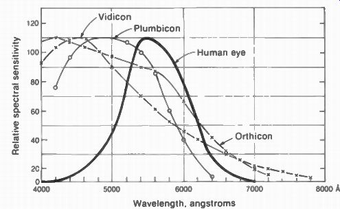
FIGURE 3-13 COMPARISON OF SENSITIVITY TO LIGHT OF DIFFERENT WAVELENGTHS FOR
ORTHICON. VIDICON, AND PLUMBICON CAMERA TUBES (NORTH AMERICAN PHILIPS CO INC)
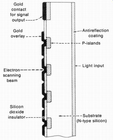
FIGURE 3-14 CONSTRUCTION OF TARGET PLATE OF SILI CON PHOTODIODES ( BELL TELEPHONE
LABORATORIES)
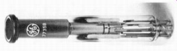
FIGURE 3-15 EPICON CAMERA TUBE USING SILICON DIODE ARRAY FOR TARGET PLATE.
TUBE DIAMETER IS 1 IN. (GENERAL ELECTRIC)
3-5 Silicon Target Plate
This type of target is not deposited on the glass faceplate of the camera tube. Instead, the target is prepared from a thin N-type silicon wafer. The final result is an array of silicon photodiodes for the target plate. Then the silicon-diode target plate is mounted in a vidicon-type camera tube.
The advantages of the silicon-diode array are resistance to burns from excessive 'light, low lag time, and high sensitivity for visible light, which can be extended to the infrared region.
The silicon target plate is typically 0.001 in. thick and about 1/2 in. square. One side is oxidized to form a film of silicon dioxide, which is an insulator. Then by photolithographic processes similar to those used in making miniature integrated circuits, an array of openings is produced in the film. This layer with its holes is used as a diffusion mask for producing the individual photodiodes. The doping element boron (B) s vaporized through the array of holes, forming islands of P-type silicon on one side of the N-type silicon substrate. An overlay of gold is centered on each P-type area (Fig. 3-14). The resulting PN photodiodes have a diameter of 0.0003 in. A typical array has 540 x 540 diodes.
In typical operation, the N-type silicon substrate or platform has +10 V applied. Positive polarity on the N-side reverse-biases the photodiodes. The electron beam in the camera tube scans the photodiode side, depositing electrons on the gold. From the opposite side, light on the target plate penetrates the silicon substrate to make it less negative. As a result, the reverse bias is reduced on the N-side of the photodiode. Furthermore, the scanning beam reduces the reverse bias on the P-side. The signal current then consists of increases of target current for more light as each element is scanned by the electron beam. A typical value of peak target current is 0.7 µA for white highlights of 1 footcandle. A camera tube using a silicon-diode array tor the target plate is shown in Fig. 3-15.
This type has the general name of silicon diode array vidicon.
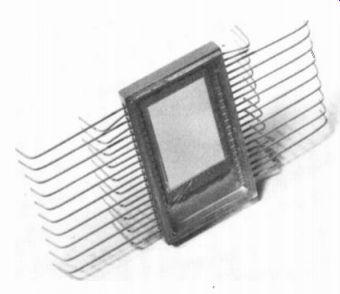
FIGURE 3-16 SOLID-STATE IMAGE SENSOR SIZE IS x IN.. WITH 120,000 ELEMENTS
(RCA)
3-6 Solid-State Image Sensor
This new device consists of a flat silicon chip with an array of metal electrodes. Figure 3-16 shows such an image sensor 3/4, x 1/2 in., containing 120,000 elements. It does not need an electron gun, scanning beam, high voltage, or vacuum envelope of a conventional camera tube, since the entire image-sensor assembly is contained in the one chip of solid-state semi conductor.
The silicon chip is oxidized on one side with a linear array of electrodes deposited on this surface. The electrodes operate in groups of three, with every third electrode connected to a common conductor. The spot under the center of each triplet serves as one light-sensitive element, or resolution cell.
In operation, the image is focused onto the silicon chip. The light causes electrons to be produced within the silicon. More charges are generated with more light. In each trio, the center electrode is the most positive. The charges generated by that element collect at the surface of the silicon under this center electrode. As a result, the pattern of collected charges represents the image.
The charge at one element is transferred along the surface of the silicon chip by applying a more positive voltage to the adjacent electrode, while reducing the voltage on the electrode over the charge packet. The change is applied by voltage pulses in successive order to all the elements. This method of dissecting the image is equivalent to scanning. When the charge packets reach the output electrode, they are collected to form the signal current. The potential required to move the charges is only 5 to 10 V. Transferring the charges from one element to the next is called charge coupling. This type of image sensor, then, is a charge-coupled device (CCD).
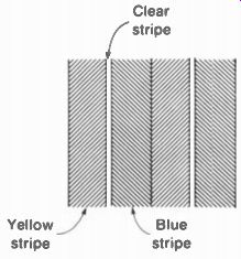
FIGURE 3-17 COLOR STRIPES FOR SPECTRAFLEX CAM ERA TUBE (RCA)
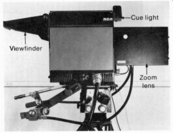
FIGURE 3-18 STUDIO-FIELD COLOR CAMERA (RCA)
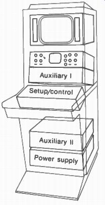
FIGURE 3-19 CONTROL CONSOLE FOR
CAMERA IN FIG 3-18. (RCA)
3-7 Spectra flex Color Camera Tube
The construction is similar to a vidicon, but the faceplate has a dichroic stripe filter to separate colors for the target. As illustrated in Fig. 3-17, the dichroic filter results in vertical stripes of yellow and cyan, which is blue-green. The clear stripes between are for monochrome.
When the electron scanning beam sweeps across the target plate, the stripe pattern generates subcarrier frequencies for two color signals and the luminance signal. A third color signal can be derived by mixing the two color signals in the proper proportions. As a result, one camera tube can supply all the information needed to reproduce a color picture.
3-8 Television Cameras
Figure 3-18 shows a color camera that can be used either for studio work or for remote pickup assignments in the field. This camera head has three plumbicons, with built-in color filters and a beam splitter. It uses just one lens, which is the motorized zoom type for a wide range of focal lengths. The viewfinder shows the cameraman a reproduction of the scene, on a monochrome picture tube with an 8-in. screen. Note the cue light at the top. This light shows when the cam era is connected to be on the air." The camera can be operated at light levels as low as 5 foot- candles in the scene. However, typical operation is with an illumination of 125 footcandles, with an f/4 lens opening.
FIGURE 3-20 COLOR FILM CAMERA, WITH THREE VIDICONS (RCA)
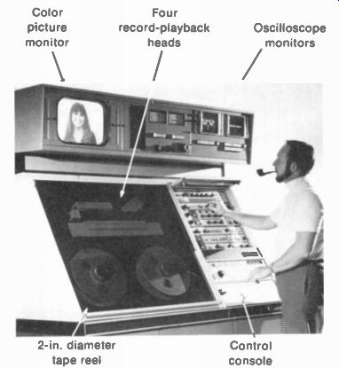
FIGURE 3-21 VIDEO
TAPE MACHINE FOR COLOR TELEVI SION BROADCASTING. (AMPEX CORPORATION)
The camera signal output is 1 V peak to peak for the coaxial cable input to the control room. As shown in Fig. 3-19, the control console includes a monitor picture tube and oscilloscope monitor below it. The control desk switches cameras, provides special effects, and sets black level. The auxiliary panels include the generators for synchronizing pulses and the 3.58-MHz color subcarrier. A camera with its control equipment is a camera chain.
Televising motion-picture films and still slides. A separate studio is used, containing projectors for 35- and 16-mm film. In addition, slides are used for station identification and titles. The projector throws the light image directly onto the image plate of the camera tubes in the film camera (Fig. 3-20). A mirror tri-plexer enables one film camera to be used with three projectors.
When commercial motion-picture films are televised, a special projector is necessary to convert from 24 to 30 frames per second. The film moves at 24 frames per second to keep the sound track normal, but an intermittent shutter projects 60 images per second. Specifically, one film frame is projected for two television fields ( 2/60 s), but the next frame is scanned with three fields (3/60 s). After four film frames, the two extra fields make five television frames. The time for four film frames is 4/60 or 1/6 s. Similarly the time for five television frames is 5/30 s, which is also 1/6 s. As a result, the time for scanning 30 television frames matches the 24 film frames.
Video tape. Most studio programs are recorded on video tape, for broadcasting at a convenient time. Also, the tapes are available for rebroadcasting by stations in different areas.
Figure 3-21 shows a video tape machine for broadcast use in color television. There are four record-playback heads, mounted on a wheel rotating at 14,400 rpm. The heads are phased 90° apart so that the four gaps contact the tape in sequential order. As a result, the video signal is recorded as a series of transverse tracks across the tape. The sound signal is recorded on a separate track.
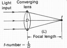
FIGURE 3-22 FOCAL LENGTH AND f-NUMBER OF AN OPTICAL LENS. D IS LENS
DIAMETER.
---------------
TABLE 3-1 TYPES OF CAMERA TUBES
TYPE
Image orthicon L Vidicon Plumbicon L Silicon diode array vidicon
SIZE
Length 15-20 in.; Ph diameter 3-4 in.
Length 5-8 in.; S diameter 0.6- p 1.6 in.
Length 8 in.; Pb diameter 1.2 in. p Length 6 in.; diameter 1 in.
IMAGE PLATE
Photocathode
Selenium photoconductor PbO photoconductor
Silicon-diode array
TYPICAL SIGNAL CURRENT, µA DARK WHITE N 30 6 Hi
0.02 0.4
0.004 0.3 Si
0.01 0.6 Lo
NOTES
High quality; high sensitivity; signal current maximum for black
Simple construction; used for film pickup; has photoconductive lag for low light levels Simple construction; 2, low lag; sensitivity low for red light Low lag; sensitive 2, to red and infrared light
IFE, hr
1,500 6,000 5,000-20,000
000-3,000 ,000-3,000
-------------------
3-9 Definitions of Light Units
Optical lenses are made of glass or plastic, with the function of concentrating light. A converging lens can bend parallel rays of light inward to converge at a point, as shown in Fig. 3-22. The focal point f is where the light rays converge.
Past this crossover point the image is inverted, left to right and top to bottom.
Focal length. This length is the distance from the lens to point I. Typical values are 5 to 20 in.
A short focal length is a wide-angle lens, as a wide field of view is focused at f. A long focal length is a telephoto lens allowing a closeup image for the same distance of lens to subject.
f - number. This number is the focal length divided by the diameter of the lens. For a focal length of 12 in. and lens diameter of 1.5 in., the f-number is 12 in./1.5 in. = 8. This is an f/8 lens, therefore. The smaller the f-number, the more light the lens takes in, which is a fast lens. The lens is rated at its maximum f-number, but it can be stopped down by an iris diaphragm for smaller openings.
The usual f stops are 1/1.4, f/2, f/2.8, 1/5.6, f/8, f/11, f/16, and f/32. These values are chosen for each higher f stop to allow exactly one-half the light of the previous stop. Smaller f stops are used when maximum light is necessary, but a higher f stop allows better depth of focus. This means that subjects a little closer or farther from the best distance for focus will still be sharp.
Illumination. Originally, the light from a standard candle was used as a reference, the intensity of this source being defined as 1 candlepower or simply 1 candle (cd). When the source is at the center of a hollow sphere with a radius of 1 ft, the amount of luminous flux on 1 ft' equals 1 lumen (I m). Since the surface area of the sphere is 4;7 ft', and 1 Im is for 1 ft', a 1-cd source provides 477 Im of light radiation. As an example, a 25-W bulb as a light source has an illuminating power of 20.7 cd or 260 Im. These units correspond to power, as they define the rate at which light energy is being radiated.
The illumination on a surface, such as the image plate, is the amount of light energy received from a source per unit area of the illuminated surface. One footcandle is the illumination for 1 ft' at a distance 1 ft away from a source of 1 cd. Therefore, 1 footcandle and 1 Im/ft" rep resent the same amount of surface illumination.
For example, the desired illumination for reading is about 10 footcandles, or 10 Im/ft". Wavelength. Different wavelengths of light have different hues, such as red, green, and blue. The unit is the angstrom (A) ecual to 10^-1 m, the micron of 10-6 m, or the milli-micron of 10 " m. The visible spectrum of colors extends from about 4500 A for blue, through 5500 A for green, and 6500 A for red. These hues are shown in color plate VIII. Longer wavelengths for infrared are not visible to the human eye. Also, shorter wavelengths below 4500 A for ultraviolet are not visible.
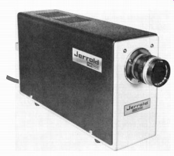
FIGURE 3-23 SMALL MONOCHROME CAMERA WITH VIDICON FOR CLOSED-CIRCUIT TV. LENGTH
OF THE CASE IS 11 IN. (JERROLD ELECTRONICS CORPORATION)
SUMMARY
The characteristics of the image orthicon (1.0.), vidicon, plumbicon, and silicon diode array vidicon are summarized in Table 3-1. The vidicon and plumbicon are the camera tubes generally used in television broadcasting This includes live scenes in the studio, film cameras, and portable TV cameras, either in color or monochrome.
Also included are applications in closed-circuit TV for education, surveillance, and medical electronics. Because of its small size and low cost, the vidicon is often used in compact monochrome television cameras (Fig. 3-23). The silicon diode-array vidicons are also used for closed-circuit TV, but are not considered to have the quality for broadcast use.
Self-Examination (Answers at back of guide)
Answer: True or False.
1. A photocathode emits more electrons with more light.
2. A photoconductor has less resistance with more light.
3. The milli-micron is a unit of wavelength equal to 10^-9 meter.
4. In the image orthicon, maximum white on the photocathode produces maximum positive charge on the glass target plate.
5. Camera signal output of the image orthicon is taken from the photocathode in the image section.
6. The image orthicon has high sensitivity because of charge storage by the target plate and the use of an electron multiplier.
7. Dichroic mirrors can split white light into colors.
8. In a camera with four camera tubes, one is for the Y luminance signal.
9. In the vidicon and plumbicon, the signal output is taken from the target plate.
10. In the image orthicon, the return beam provides the variations in camera signal.
11. The image orthicon uses silicon photodiodes for the target plate.
12. The plumbicon uses lead monoxide (PbO) for the target plate.
13. The amount of target voltage in the vidicon and plumbicon determines the amount of dark current.
14. At low values of dark current in the vidicon, lag in the photoconductive layer can produce a tail that follows fast-moving objects in the scene.
15. Typical output current for the vidicon and plumbicon is approximately 140 mA.
16. The solid-state image sensor does not use an electron scanning beam.
17. Without light on a silicon diode-array vidicon, the diodes have maximum reverse bias to limit conduction in the forward direction.
18. The cue light on the camera head shows when the camera is on the air.
19. A converging lens inverts the optical image.
20. A typical lens opening for television cameras is f/50.
Essay Questions
1. Define the following terms: photocathode, photoconductor, photoelectrons, photodiode, 1.0., and C.C.D.
2. List the types of image plate for the light image in the image orthicon, standard vidicon, plumbicon, and silicon vidicon camera tubes.
3. Give the function for each of the three sections in the image orthicon.
4. What is the difference between reverse bias and forward bias for a semiconductor diode?
5. List four semiconductor elements having a valence of 4.
6. Make a drawing to illustrate construction and operation of a standard vidicon.
Explain briefly how camera output signal is produced.
7. What is meant by "dark current" in the vidicon?
8. Explain briefly how four camera tubes are used in a color camera. Do the same for a color camera with three camera tubes.
9. List the main items of equipment in a camera chain.
10. Give one application for each of the camera tubes listed in Table 3-1.
Problems
(Answers to selected problems at back of guide)
1. With 10-µA peak-to-peak output from an image orthicon, how much is the camera signal voltage across a 20-k ohm R,?
2. With 0.42 µA from a vidicon for white highlights and a dark current of 0.02 µA, how much is the peak-to-peak camera signal voltage across a 60-k ohm R,.?
3. Refer to curve C of the vidicon light-transfer characteristics in Fig. 3-11, with 0.004-µA dark current. Give the output current produced by white highlights of 100 footcandles, as provided by film projection directly on the target.